Table of Contents
Advertisement
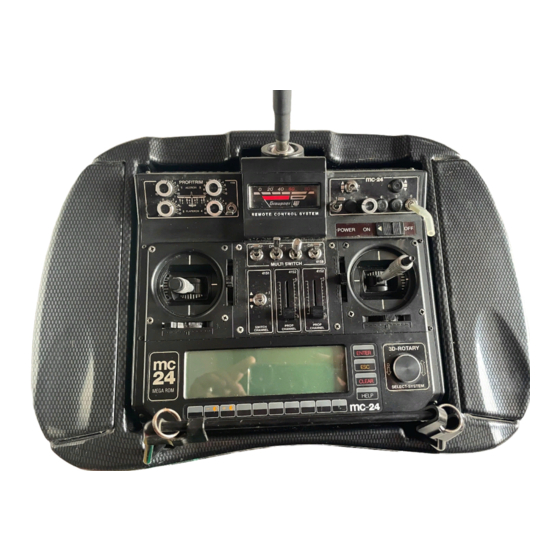
mc
-24 PROFI-ROM
Index
mc-24 PROFI-ROM
Introduction ...............................................................3
Enhanced Rotary Select Functions ..........................4
Operating Comfort & Safety......................................4
OVERVIEW IN TABLES
Operating comfort & Operating safety ......................6
Extended Functions ..................................................7
New Functions ..........................................................8
Instructions for the new Menu-Functions
Memory
Basic adjustments Transmitter, Model & Servos
Basic adjustments Model
Controls
Control Adjustments
Logic Switches
Auxillary Switches
Flight Phases
What is new ?
Phase Adjustments
Non-delayed channels
2
Introduction
Mixer
Wing - mixer
Global Functions
Basic adjustments
Flight phase-Program examples
E-Models with 2 Aileron Servos ............................. 34
Model with 2 Aileron- , 2 Flap-
and 2 Airbrake Servos ........................................... 37
Page
Page
12
12
13
13
13
17
18
18
19
19
20
20
21
21
22
23
25
25
26
(27)
28
28
Page
Page
28
33
33
Advertisement
Table of Contents

Related Manuals for GRAUPNER mc-24 PROFI-ROM


Summary of Contents for GRAUPNER mc-24 PROFI-ROM
- Page 1 -24 PROFI-ROM Index mc-24 PROFI-ROM Page Page Introduction ...............3 Mixer Enhanced Rotary Select Functions ......4 Wing - mixer Operating Comfort & Safety........4 Global Functions OVERVIEW IN TABLES Basic adjustments Operating comfort & Operating safety ......6 Extended functions ..........7 Flight phase-Program examples New functions ............8...
- Page 2 6 wing servos. Part.-Nr. 4831.660 German MEGA-SOFT-ROM have also been extended. Part.-Nr. 4831.670 English The mc-24 PROFI-ROM automatically recognises Part.-Nr. 4831.680 Italian All changes from the MEGA-SOFT-ROM to the new the presence of a Multi-Voice-Audio-Recording- Part.-Nr. 4831.690 French PROFI-ROM are compiled in a table overview in Module (Part.-Nr.
- Page 3 -24 PROFI-ROM Control-comfort and Control-safety Keep the rotary select knob down and select from Extended rotary control functions the indicated functions. Change of curve nodes Only the codes associated with the selected menu With the rotary selector depressed you will be shown in the next window when the rotary- Hotkey for quick select can move the curve nodes sideways in select-knob is released.
- Page 4 Basic transmitter display: Modulation type If no additional flight phase timer is activated in the lower field the transmitter modulation type will be displayed in the field next to the GRAUPNER -Logo. Secret code entry The secret code is no longer visable.
- Page 5 -24 PROFI-ROM All changes and new items at a glance • • Model select Faster model change: Select with -Key Code 11 » Model select « ,select model followed by a short push on the rotary select knob. A short push on the rotary select knob is equal to pressing the Enter key.
- Page 6 -24 PROFI-ROM All changes and new items at a glance on E • • Copy/Erase Undo changes: Programming changes ca e undone. This w set the program data back to where it was at the last model memory change or when you last “stored changes permanently“.
- Page 7 Throttle warning-limit: The warning threshold for „Throttle too high“ after transmitter switch-on can be adjusted from –100% to 0% with reference to the selected pitch-minimum direction. The default value ( CLEAR ) = -70%. • • Control adjust Input 5...12: You can now nominate for any input for ch 5 to ch 12 the CH 1 controller, the CH 1 trim lever (operates like a linear slider) or 2 switches for a total of 3 functions.
- Page 8 -24 PROFI-ROM All changes and new items at a glance r m e • Phase settings Apart from the phase “Autorotation“ - 7 other free selectable phase names can be programmed. The switch for (previously: „Autorotation“is selected in Code 49 » Auxiliary switch « all other phase switches in the new code Code 52 Phase assignment) »...
- Page 9 ri t • Wing mixers The newly constructed and easy to navigate wing mixer menu now allows the control of 6 wing servos. Which of the functions are accessible depends on the selected model-type in Code 22. Multi-flap-menu: flight phase dependant adjustments of mixer functions for ailerons and the two pairs of flaps (FL = middle flap-pair and FL2 = inner flap-pair).
- Page 10 SOFT-ROM as with multi-voice-audio-recor ding- modules (Part.-Nr. 4130) and transmitters with the and “Copy MC24 → external“, Other than the comm new mc-24 PROFI-ROM (Part.-Nr. 4831.660 Sollen die Programmänderungen all used mod el memories are automatically and geschrieben werden? successively tranfered to the PC.
- Page 11 Code 21 Code 22 Base setup model Model-type Model specific basic programm Selection of fixed wing model type With the two arro keys (l eft or right) can the new This menu initialises all model characteristic mixer GRUNDEINSTELLUNGEN MODELL character be plac ed in t e re uired p osition.
- Page 12 Importand notice: Connecting details for PPM- and PCM- or SPCM- Batt Elevator function on a model with receivers: Wölbklappe 2 rechts aileron and camber flap must be Wölbklappe 2 links frei (Schleppkupplung) programmed in the wing mixer 1. PPM-receiver: Wölbklappe rechts menu, see page 30! Wölbklappe links If you use a PPM-receiver connect the servos...
- Page 13 If you want to set the offset into one of the two controllers you will have to adjust it to –100% or Without mixing, the servos connected to the two +100%. outputs (9+10) will run “jitter“ free. links 2. PCM- and SPCM-receivers: Code 85 »...
- Page 14 switch for this. Control stick switches with Part.-Nr. The neutral offset can be moved to any position: 4143 or 4113, can be use for this.) Just move the controller on inputs 1, 7, 8 or 9 in the desired position at which the landing flaps should be How can aileron and camber flap pairs be in neutral and set the „Offset“...
- Page 15 Code 22 Heli type odel type programming for helicopter models H E L I T Y P Taumelscheibentyp 1 Servo Linearis. Taumels. nein Rotor-Drehrichtung links Pitch min vorn Expo Gaslimit Grenze Gaswarnung - 70% This menu has now two further options: ”Linearisation of the swash plate control“...
- Page 16 Code 32 Control adjust Selecting and adjusting of controls oloumn 2 “Control- and Switch selection“: Eing. 5 Geb. 5 0% +100%+100% 0.0 0.0 Eing. 9 9 10 0% +100%+100% 0.0 0.0 elect with the rotary control “controller1“ or “trim 1“. Eing.
- Page 17 Code 43 Logical Switches Combination of two switches “ OR“-function: The logical switch is already Note to inverted switches: L O G I S C H E S C H A L T E R closed when at least one of the two individual With inverted switches is the switch function switches is closed.
- Page 18 Code 49 Code 49 Auxiliary switch Auxiliary switch Program-automatic-, Trim switch Autorot.-switch, Marker key, INC-, DEC-Switch Trim-, PROFI trim-, INC-, DEC-Switch The trim adjustment is memorised and indicated Progr.autom. Schalter 1 Autorotation the flight phase dependant Code 53 » Phase trim «. Progr.autom.
- Page 19 Flight Phase Program What is new? „INC (+)“ and “DEC (-)“: The flight phase menus Code 52 and Code 53 ha The next step sets the requ ired “phase switches“ in been totally reconstructed. Code 52 » Phase assignment «. The two new switches make it possible to change As a result the programming is now much simp lified.
- Page 20 Code 51 Phase adjust Programming of flight phases List of flight phase dependant menus for “Name“: Press the -key and use the rotary Phase 1 0.0s helocopter models: selector to choose a name from the list Phase 2 0.0s for the required phases. Phase 3 0.0s Code...
- Page 21 Code 51 Phase adjust Programming of flight phases „Fl.ph.tim. “: Apart from the normal timers in the Application: Autorot Autorot 0.0s default display are a numb er of other timers Timing of motor run if the same switch Phase 1 0.0s available.
- Page 22 TIP: »Flight phase timers «, Page 71 of the Tim 2 ”Tim2“ stores the “OFF“ and the “ON“ time Of help during programming of the various flight mc-24/1-hand book. of the relevant switch i.e. the timer restart phases is the command “Copy flight phase“ in Code with every switch action an d the counter 2 »...
- Page 23 Code 52 Phase assignment Selection of flight phase switches Programming of flight ph ase switches: P H A S E N Z U W E I S U N G e aux iliary, control and logical switches are selected by pressing the key under the switch prior kombi P H A S E N Z U W E I S U N G...
- Page 24 Code 53 Phase trim Flight phase dependant trimming for AIL, EL, RUD Phase switches & Location Phase-number normal & Trim. Pos Phase-na Strecke 1. Trim with rotary selector Landung 1 normal Select t he desired flight phase. In the line marked by 2 distance a star you dia l in the requi...
- Page 25 Code 53 Phase trim Flight phase dependant trim of Roll, Pitch and Tail (1% bei 100% Tr. red..aprox. 0,25% by smaller ew in the Heli program of the mc-24 PROFI ROM normal Trim. Pos 25% Tr. red.). only the Code-Number for this menu. The Strecke The storing of the actual trim lever positions is n contents of the menu was tranfered from the...
- Page 26 Code 58 Code 71 Non delayed channels Wing mixer Channel dependant switch delay Sub menus depending on Code 22 »Model type« Multi-Flap-Menu: N V E R Z Ö G E R T E N Ä L E F L Ä C H E N M I S C H E R If you have line “Multi-flap menu“...
- Page 27 24/1-hand book, page 75. WK : In this line you enter with the keys The adjustment range from -100% to the characteristic effect for the +100% allows the correct adjustment of Code 32 » Control adjust « accomplished differential movement independant of the links links links...
- Page 28 EL->FL: This mixer couples the ailerons and Brake adjustments: camber flaps to the elevator control. The Other tha n in the previous mc-24-Software are the +100% mixer should move the flaps and/ following adjustments for the “brake mixer“ no longer QR-Tr.
- Page 29 If the differential reduction value is compen sation. higher than the differential value, This mixer is described further down. the new mc-24 PROFI-ROM-Software works a little different. To be able to eliminate a mechanically induced differential with the electronic – an inverse differential:...
- Page 30 EL-curve: This function contains the mixer Brake -> Elevator. directi on to the opposite end po sition to It means that – if the brake flaps are r reqirements: AILE. >4 RUDD.: This mixer moves the rudder deployed as selected in Code 22 » Mode with movement of the aileron stick.
- Page 31 Code 91 Basic settings Basic transmitter adjustments Hint for the activation of air-brakes: second display with th e list of symbols and program ALLGEMEINE GRUNDEINSTELLUNGEN If you inst lled, apart from aileron and camber flap as in creation of “Owners name“ Besitzername <Uwe Corbach >...
- Page 32 Start a new phase name preferable with Nr 1 or use -key to the next available free place. ! “ # $ % & ´ ( ) * + , - . / 0 1 2 3 4 5 6 7 8 9 : ; < = > ? @ABCDEFGHIJKLMNOPQRSTUVWXYZ[¥...
- Page 33 Programmierbeispiele Verwenden von Flugphasen The following two examples will introduce you to the he CH1 controller (= +100% Offset. Please observe flight phase programming possibilities of fixed wing he note on page 16). odels. At this point in time it can not be done with the CH1 controller but only with the slider control conne cted to the transmitter PCB.
- Page 34 Programming examples Application of flight phases Before we do anything else we have to nominate Enter “Free“ for the input 7 “Brake“ as we do not This way of programming has the same effect as one of the auxiliary switches for the change of the want to use the ailerons as brake in flight phase you will see if you press the rotary control and two phases “Start“...
- Page 35 The display indicates in the “Start“-phase the If necessary you have to select an elevator movement of servos 1+6 with the movement of the compensation for the extension of the landing flap in CH 1 control stick and in phase “Landung“ the “El-curve“...
- Page 36 Programming examples Application of flight phases Example 2 Batt Glider with 4-Wing-Servos, 2 Air-brake-servos frei With “- travel +“ you ca n adjust the control throw for Schleppkupplung and Tow Release Bremsklappe rechts the two end positions of the switch. Check it out with Wölbklappe rechts We show you in the second example how you can a short push on the rotary knob in »...
- Page 37 In the Multi-Flap-Menu of ... HR->WK: This mixer moves the ailerons and/or Perhaps now the time has come for the first test camber flaps with movement of the flying providing all global functions - (flight phase Code 71 “Wing mixer“, page 28 elevator control stick.
- Page 38 Programming examples Application of flight phases We now select for the two flight phases in... Code 12 »Copy/Erase«, hand book mc-24/ 1, page To be able to move the camber flaps in the Code 52 »Phase assignment«, page 25 “Thermal“-phase you must first select for ... Modell löschen =>...
- Page 39 Place switch toggle in centre position. It is advisable to select in column “-time+“ a Move the CH 1 control stick to the full foreward symmetrical or asymmetrical delay time between the position so that you may identify the position of the three switch positions for a “soft“...
- Page 40 Programming examples Application of flight phases Code 53 »Phase trim«, page 26, normal Trim. Pos Thermik «Thermik» to compensate the elevator basic setting in the flight phase. Activate the phase “Thermal“ with the flight phase switch and adjust the reqired elevator trim value in cloumn EL .
- Page 41 Programming examples 43...
- Page 42 Personal notes...
Need help?
Do you have a question about the mc-24 PROFI-ROM and is the answer not in the manual?
Questions and answers