
Related Manuals for GRAUPNER GM Genius Pro Series


Summary of Contents for GRAUPNER GM Genius Pro Series
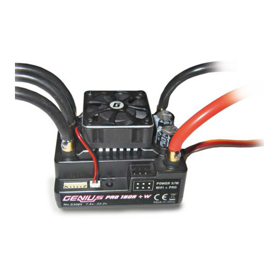
- Page 1 Manual GM Genius Pro Speed controller with telemetry and W-LAN module (optional) No. S3084 (60R) No. S3086 (120R) No. S3078 (160R) No. S3085 (180R)
-
Page 3: Table Of Contents
Introduction ................4 Service Centre ................4 Intended use ................5 Package content ............... 5 Technical data ................6 Symbols explication ..............7 Safety notes................7 Connection example ..............9 Battery plug connection............9 Installation ................10 Installation in the model and commissioning ....... 10 Motor connection .............. -
Page 4: Introduction
This manual is part of that product. It contains important informa- tion concerning operation and handling. Keep these instructions for future reference and give it to third person in case you gave the product. Service Centre Graupner Central Service Servicehotline Graupner/SJ GmbH (+49) (0)7021/722-130 Henriettenstraße 96... -
Page 5: Intended Use
For any improper use no warranty or liability is accepted. Read through this entire manual before you attempt to install or use the speed controller. Graupner/SJ constantly works on the development of all products; we reserve the right to change the item, its technology and equip- ment. -
Page 6: Technical Data
Technical data Product name GENIUS PRO GENIUS PRO GENIUS PRO GENIUS PRO 180R 60R for W-Lan 120R for W-Lan 160R for for W-Lan W-Lan S3084 S3086 S3078 S3085 Type Only Sensored Hybrid / 4Pole Hybrid / 4Pole Only HYBRID / brushless sensored brush- sensored brush-... -
Page 7: Symbols Explication
Symbols explication Always observe the information indicated by this warning sign. Par- CAUTION ticularly those which are additionally marked with the WARNING WARNING . The signal word indicates the poten- CAUTION tial for serious injury, the signal word indicates possibil- ity of lighter injuries. - Page 8 Only use the components and spare parts that we recommend. Always use matching, original Graupner plug-in connections of the same design and material. Make sure that all of the plug-in connections are tight. When dis- connecting the plug-in connections, do not pull the cables.
-
Page 9: Connection Example
Connection example S3084 S3085 Bat.- BATTERY MOT.C Sensor wire MOT.B MOT.A Bat.+ Power switch PRO / Wifi FAN Connector Receiver Battery plug connection The battery cables must be provided with a suitable, polarity-pro- tected plug-in system. To protect against polarity reversal and for secure connection, use batteries with the same connector system only. -
Page 10: Installation
correct polarity. Connect the W-Lan module to the "PRG" port. Pay attention to the correct polarity, the signal wire is marked. Mount the fan on the cooling block using the four screws supplied. Connection to the "FAN" port. Attention Inverted polarity would destroy the speed controller. Installation Mount the speed controller in the model such that the cooling sur- face remains exposed. -
Page 11: Motor Connection
Motor connection The motor is connected to the speed controller through the three black cables (G 3,5 connectors). Solder the related G 3,5 connectors No. 2970 to the motor cables. The three motor cables can alterna- tively be soldered directly to the three black cables of the speed con- troller. -
Page 12: Setting The Throttle Travel
Setting the throttle travel Note This initial adjustment of the throttle lever is only necessary if you use another transmitter or if the settings have been changed. Switch on the transmitter ("ON"), then place the throttle lever in the "neutral" position and stop. The throttle and brake on the transmit- ter should be set to 100. - Page 13 Settable values in the program Programmable Parameter Values Default Items Motor Type Sensor only for S3084,S3086,S3078 Hybrid only for S3078,S3086,S3085 Sensor Select Battery LiPo / LiFe / NiMH (NiCd) LiPo Disable / Auto / 3.0V ~ 7.5V (Step:0.1V) Cut Off Voltage Auto Disable / Auto / 6.0V ~ 23V (Step:0.1V)_S3085 Power Curve...
- Page 14 Special characteristics Advanced timing If the Advanced timing value is decreased, the power consumption and the temperature of the motor are also reduced. The maximum speed and acceleration are also reduced, thus increasing the battery life. If the Advanced timing value is increased, the power consumption and the temperature of the motor are also increased.
-
Page 15: Led Error Display
Throttle position Green LED Red LED Neutral Neutral (0-boost) flashes Full throttle Full braking ESC data view in the telemetry menu Telemetry data display on a Graupner / SJ HOTT transmitter [ESC] DATA VIEW <> Curr 5.3Max 3.0A Volt 7.5Min 7.6V 29 °... -
Page 16: Programming With Hott Transmitter
Programming with HoTT transmitter Operation of the GM GENIUS PRO speed controller is similar to operation of the corresponding transmitter. You should read the manual of your remote control system, especially the chapter "telem- etry". The operation is done in the transmitter menu "Telemetry" under the display "SETTING AND DATA VIEW". - Page 17 Model (Motor type) You can set the motor type Sensorless = Hybrid, Sensored = sensor setting. Battery (battery type) You can set the battery type here LiPo / LiFe / NiMh (NiCd). If the battery type is changed, the low-voltage cut-off voltage is set automatically to the AUTO mode.
- Page 18 Boost Max-rpm • Set the maximum RPM limit for the boost timing. For example, with a boost value set to 20-degrees and maximum RPM set at 20000, the boost will cap out and hold at 20-degrees once the ESC crests 20000. This option can be set between 0~65000 but cannot be lower than the Boost Min RPM.
- Page 19 Start power (Start power) You set the start power here. 0 - 100 (Step: 1%) You use this function to set the minimum start power when the motor starts to run. It is comparable to a minimum amount of throt- tle.
- Page 20 Max-reverse (maximum reverse speed) You set the maximum reader speed here: 20% ~ 100%. The maximum reverse speed determines the maximum power that is available when driving in reverse and permits reduction of the acceleration and speed when driving in reverse in mode Two Way 1, 2 or 3.
- Page 21 Maximum brake Here you can set the maximum brake 0~100%. Here you can set the maximum brake for the full brake position. (Practical values: 70 ~ 80%) (Braking range: minimum braking effect ~ maximum braking effect) Soft Brake Set the power to break hard or break soft. Note: Hybrid Mode only supports a soft break.
-
Page 22: Connection With The W-Lan Module
Y cable (No.S8186). When the W-Lan module is connected, no telemetry transmission can be displayed in the transmitter display! A detailed tutorial video can be found on our Graupner Youtube channel. The link is available on , directly in the www.graupner.de... - Page 23 Warning messages Indicators in the telemetry menu Setting the alarm thresholds Minimum battery voltage (Page 2) Minimum battery voltage: Warning threshold for the minimum bat- tery voltage during operation, warning threshold adjustable between 3.0 and 23.0 V Factory setting: 3.0 V, signal tone: P Warning: Off Maximum speed controller temperature (Page 3) Maximum speed controller temperature (temperature): Warning...
- Page 24 Settable warning messages [ESC] WARNING <> E.S.C] *SENSORLESS > >Set warning : page 1 User setup : page 1 E.S.C save? >MODEL HYBRID Factory set ? E.S.C save? E.S.C] *SENSOR > Factory set? User setup : page 1 >MODEL SENSOR Ver:P 2.080 E.S.C save? Ver:P 1.000...
-
Page 25: Graphical Display Of Telemetry Data
Graphical display of telemetry data To display the telemetry data, please read the instructions of your RX–S QUA: 100% remote control system or of the SMART-BOX. RX–S ST : 100% EMPFÄNGER RX–dBm: GENERAL 33dBm TX–dBm: ELECT. AIR 33dBm This display visualizes the data of the speed controller. It has the fol- V–PACK: VARIO 10ms... -
Page 26: Warning Messages
26 / 32 S3084_S3086_S3078_S3085_MP_V1... -
Page 27: Firmware Update
Disconnect the controller from the receiver, the power supply and a motor. 5. Connect the speed controller to the PC Required accessories: USB interface for Graupner/GM-GENIUS 7168.6 USB interface adapter cable for HoTT 7168.S Battery Connect the adapter lead No.7168.6 to the USB interface and con- nect the usb cable to your PC. - Page 28 Disconnect the 3-wire connection cable of the speed controller from the receiver. Connect the 2 wire end of the adapter cable (Item no. 7168.S) to the telemetry jack (see page 7) on the speed controller. Now connect an operating battery (do not exceed the max. permis- sible operating voltage!) to the appropriate connections on the con- troller.
-
Page 29: Declaration Of Conformity
Declaration of conformity No. S3084 (60R) No. S3086 (120R) No. S3078 (160R) No. S3085 (180R) Graupner/SJ declares that the product is conform to EU norms. EMV 2004/108/EC: EN 301 489-1 V1.9.2 EN 301 489-17 V2.1.1 EN 62479:2010 LVD 2006/95/EC: EN 60950-1 + A11 + A1 + A12 + A2:2013 R&TTE 1999/5/EC:... -
Page 30: Notes On Environmental Protection
The present construction or user manual is for informational pur- poses only and may be changed without prior notice. The current version can be found on the Internet at www.graupner.de on the rel- evant product page. In addition, the company... - Page 31 Notes 31 / 32 S3084_S3086_S3078_S3085_MP_V1...
Need help?
Do you have a question about the GM Genius Pro Series and is the answer not in the manual?
Questions and answers