
Related Manuals for Galmet Basic Series


Summary of Contents for Galmet Basic Series
- Page 1 PP-004869 Instrukcja obsługi i montażu Pompa ciepła powietrze-woda Basic Installation and operation manual Air-Water heat pump Basic Made in Poland www.galmet.com.pl...
-
Page 2: Table Of Contents
4.8. Podłączenie pompy dodatkowej ..................................19 4.9. Podłączenie pompy cyrkulacyjnej ..................................20 Niewłaściwa praca ........................................21 Deklaracja zgodności ........................................23 Prosimy o uważne przeczytanie instrukcji przed rozpoczęciem wykonania instalacji i użytkowaniem produktu. Instrukcja pompy ciepła Basic © Wszelkie prawa zastrzeżone - Galmet Sp. z o.o. Sp. K... - Page 3 4.9. Connecting circulation pump ...................................40 Troubleshooting ..........................................41 Declaration of Conformity ......................................43 Please read the instructions carefully before beginning the installation and use of the product. © Wszelkie prawa zastrzeżone - Galmet Sp. z o.o. Sp. K Instrukcja pompy ciepła Basic...
-
Page 4: Eksploatacja I Obsługa
Przybliżony czas nagrzewania wody [h] Średni pobór prądu [W] wlotowego Basic 200 Basic 270 Basic 300 Basic 200 Basic 270 Basic 300 +35°C +20°C 10,5 +15°C +7°C 14,5 Instrukcja pompy ciepła Basic © Wszelkie prawa zastrzeżone - Galmet Sp. z o.o. Sp. K... -
Page 5: Opis Sterownika
°C maksymalna temperatura pracy wężownicy °C typ zbiornika SGW(S) SGW(S) SGW(S)B SGW(S) średnica zbiornika wysokość zbiornika 1140 1360 1360 1460 EN-16147 A15W10-55 EN-16147 A20W10-55 © Wszelkie prawa zastrzeżone - Galmet Sp. z o.o. Sp. K Instrukcja pompy ciepła Basic... -
Page 6: Konserwacja
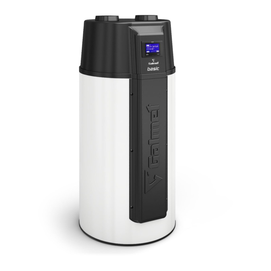
3. Przed przeniesieniem sprawdź czy na drodze do miejsca instalacji urządzenia nie znajdują się żadne przeszkody. 4. Urządzenie powinno być transportowane w oryginalnym opakowaniu. 2. Informacje ogólne 2.1. Ogólny widok Basic 200 Basic 270 Basic 300 Instrukcja pompy ciepła Basic © Wszelkie prawa zastrzeżone - Galmet Sp. z o.o. Sp. K... -
Page 7: Ogólne Wymiary
2.2. Ogólne wymiary 1245 1245 Basic 200 Basic 300 1120 1120 1125 1125 1040 1040 Basic 270 z jedną wężownicą Basic 270 z dwiema wężownicami © Wszelkie prawa zastrzeżone - Galmet Sp. z o.o. Sp. K Instrukcja pompy ciepła Basic... -
Page 8: Sposób Transportu
Pompę ciepła Basic zalecamy przenosić na palecie w pozycji pionowej (stojącej) za pomocą pasów dostarczonych z urządzeniem. Pasy te znajdują się pomiędzy pompą ciepła, a paletą (na rysunku oznaczone kolorem czerwonym). Instrukcja pompy ciepła Basic © Wszelkie prawa zastrzeżone - Galmet Sp. z o.o. Sp. K... -
Page 9: Montaż
1,5 m! W przypadku pracy urządzenia na powietrzu obiegowym z pomieszczenia należy zapewnić odpowiednią wentylację pomieszczenia oraz zweryfikować czy kubatura pomieszczenia jest odpowiednia. © Wszelkie prawa zastrzeżone - Galmet Sp. z o.o. Sp. K Instrukcja pompy ciepła Basic... -
Page 10: Zamontowanie Pompy Wewnątrz Budynku
3.3. Usytuowanie pompy ciepła wewnątrz pomieszczenia Należy zapewnić odpowiednią odległość między kanałem zasysania i wyrzutu powietrza. Należy zapewnić odpowiednią wentylację pomieszczenia, a jego kubatura powinna wynosić minimum 30 m Instrukcja pompy ciepła Basic © Wszelkie prawa zastrzeżone - Galmet Sp. z o.o. Sp. K... -
Page 11: Zasilanie Pompy Ciepła Z Zewnątrz Oraz Wyrzut Powietrza Do Innego Pomieszczenia
- przynajmniej raz w roku czyścić parowacz antybakteryjnie. 3.5. Zasilanie pompy ciepła z pomieszczenia i wyrzut powietrza na zewnątrz Pomieszczenie gospodarcze np. pralnia, garaż Należy zapewnić odpowiednią wentylację pomieszczeń! © Wszelkie prawa zastrzeżone - Galmet Sp. z o.o. Sp. K Instrukcja pompy ciepła Basic... -
Page 12: Zasilanie Oraz Wyrzut Powietrza Z Pompy Ciepła Na Zewnątrz
Wszystkie rury przyłączeniowe spust wody należy zaizolować. Jeżeli następuje konieczność opróżnienia zbiornika należy tego dokonać korzystając z zaworu spustowego zamontowanego wg. schematu. Instrukcja pompy ciepła Basic © Wszelkie prawa zastrzeżone - Galmet Sp. z o.o. Sp. K... -
Page 13: Opis Techniczny
Przeznaczona dla czujnika c.w.u. sterownika dodatkowego źródła np. kotła. Miejsce przyłączenia opcjonalnej pompy cyrkulacyjnej (8) i pompy dodatkowego źródła (7). Szczegółowy opis podłączenia w dalszej części instrukcji. © Wszelkie prawa zastrzeżone - Galmet Sp. z o.o. Sp. K Instrukcja pompy ciepła Basic... -
Page 14: Króćce Przyłączeniowe
1. Odłączyć zasilanie elektryczne urządzenia 2. Usunąć zaślepkę 3. Odkręcić 2 śruby 4. Wysunąć sterownik do przodu 5. Odłączyć złącza elektryczne (kostki) podłączone w tylnej części sterownika Instrukcja pompy ciepła Basic © Wszelkie prawa zastrzeżone - Galmet Sp. z o.o. Sp. K... -
Page 15: Demontaż Pokrywy Górnej
4.5. Wymiana anod magnezowych i grzałki 1. Zdjąć panel przedni – odkręcić 6 śrub 2. Wykręcić anody z zbiornika 3. Wykręcić grzałkę z zbiornika Basic 200 © Wszelkie prawa zastrzeżone - Galmet Sp. z o.o. Sp. K Instrukcja pompy ciepła Basic... - Page 16 Anoda magnezowa ø 38 x 400 mm z korkiem 5/4’’ Basic 270 i Basic 300 (1 wymienialna anoda) W zbiorniku znajduje się dodatkowa anoda magnezowa - niewymienialna. Instrukcja pompy ciepła Basic © Wszelkie prawa zastrzeżone - Galmet Sp. z o.o. Sp. K...
-
Page 17: Schemat Chłodniczy Urządzenia
Basic 200 i 270 Presostat niskiego ciśnienia Presostat wysokiego ciśnienia Zawór 4-drogowy (rozmrażanie) Sprężarka Zbiornik Wentylator Skraplacz Zawór rozprężny Filtr / odwadniacz Basic 300 © Wszelkie prawa zastrzeżone - Galmet Sp. z o.o. Sp. K Instrukcja pompy ciepła Basic... -
Page 18: Schemat Elektryczny Urządzenia
W przypadku niepoprawnego działania urządzenia należy odłączyć zasilanie urządzenia i skontaktować się z serwisem. Jeżeli przewód zasilający ulegnie uszkodzeniu, to powinien on być zastąpiony specjalnym przewodem zgodnym z zaleceniami producenta urządzenia. Naprawa powinna być przeprowadzona przez serwis. Instrukcja pompy ciepła Basic © Wszelkie prawa zastrzeżone - Galmet Sp. z o.o. Sp. K... -
Page 19: Podłączenie Pompy Dodatkowej
źródła umieszczamy w osłonie czujnika zbiornika pompy ciepła. Przed przystąpieniem do czynności należy odłączyć napięcie z urządzenia. Podłączenie powinno być wykonane przez uprawnioną osobę (elektryka). © Wszelkie prawa zastrzeżone - Galmet Sp. z o.o. Sp. K Instrukcja pompy ciepła Basic... -
Page 20: Podłączenie Pompy Cyrkulacyjnej
Przed przystąpieniem do czynności należy odłączyć napięcie z urządzenia. Podłączenie powinno być wykonane przez uprawnioną osobę (elektryka). Instrukcja pompy ciepła Basic © Wszelkie prawa zastrzeżone - Galmet Sp. z o.o. Sp. K... -
Page 21: Niewłaściwa Praca
Migracja ciepła ze zbiornika na układ c.o. Jeżeli nie zastosowano zaworów zwrotnych, należy zamknąć zawory odcinające w okresie użytkowania pompy ciepła. © Wszelkie prawa zastrzeżone - Galmet Sp. z o.o. Sp. K Instrukcja pompy ciepła Basic... - Page 22 Utylizacja zużytych urządzeń elektrycznych i elektronicznych pomaga chronić środowisko naturalne i zapobiega negatywnemu wpływowi na ludzkie zdrowie. Instrukcja pompy ciepła Basic © Wszelkie prawa zastrzeżone - Galmet Sp. z o.o. Sp. K...
-
Page 23: Deklaracja Zgodności
PN-EN 50366:2004+s\ 17:2006 Pomiar pola elektromagnetycznego PN-EN 60335-2-40:d004+A12:2005+A11:2005+A1:2006+A2:2009 PN-EN 60335-1:200y+A1:2005+A2:2008+A12:2008+A13:2009 +A14:2010 Bezpieczeństwo użytkowania Głubczyce 01.08.2016 .................. (Miejscowość i data) (Podpis osoby upoważnionej) © Wszelkie prawa zastrzeżone - Galmet Sp. z o.o. Sp. K Instrukcja pompy ciepła Basic... -
Page 24: Proper Operation
Average power consumption Basic 200 Basic 270 Basic 300 Basic 200 Basic 270 Basic 300 +35°C +20°C 10,5 +15°C +7°C 14,5 Installation and operation manual of the Basic heat pump © All rights reserved - Galmet Sp. z o.o. Sp. K... -
Page 25: Controller Description
Coil's maximum working temperature °C Tank type SGW(S) SGW(S) SGW(S)B SGW(S) Tank diameter Tank height 1140 1360 1360 1460 EN-16147 A15W10-55 EN-16147 A20W10-55 © All rights reserved - Galmet Sp. z o.o. Sp. K Installation and operation manual of the Basic heat pump... -
Page 26: Maintenance
4. The device should be carried in its original packaging. 2. General Information 2.1. General view Basic 200 Basic 270 Basic 300 Installation and operation manual of the Basic heat pump © All rights reserved - Galmet Sp. z o.o. Sp. K... -
Page 27: Overall Dimensions
Basic 200 Basic 300 1120 1120 1125 1125 1040 1040 Basic 270 with 1 coil Basic 270 with 2 coils © All rights reserved - Galmet Sp. z o.o. Sp. K Installation and operation manual of the Basic heat pump... -
Page 28: Transportation Method
We recommend moving the Basic heat pump in vertical position (standing) by using belts included with the device. The belts are located between the heat pump and a wooden palette (marked in red on the picture above). Installation and operation manual of the Basic heat pump © All rights reserved - Galmet Sp. z o.o. Sp. K... -
Page 29: Installation
If the device works using air circulating in the room, then it needs to have proper ventilation system and the room capacity has to be checked. © All rights reserved - Galmet Sp. z o.o. Sp. K Installation and operation manual of the Basic heat pump... -
Page 30: Installing The Heat Pump Indoors
1.5 m! The room needs proper ventilation system, and its capacity should be at least 30 m Installation and operation manual of the Basic heat pump © All rights reserved - Galmet Sp. z o.o. Sp. K... -
Page 31: Air For The Heat Pump Supplied From The Outside And Discharged To Another Room
3.5. Air for the heat pump supplied from the room and discharged outside Air ducts +10°C +15°C Backup room (e.g. laundry, garage) CAUTION! Ensure adequate ventilation for the rooms! © All rights reserved - Galmet Sp. z o.o. Sp. K Installation and operation manual of the Basic heat pump... -
Page 32: Air For The Heat Pump Supplied From The Room And Discharged Outside
To empty the it is required to use the drain valve installed by following the diagram. cold water water drain Installation and operation manual of the Basic heat pump © All rights reserved - Galmet Sp. z o.o. Sp. K... -
Page 33: Technical Description
Place to which optional circulation pump (8) and additional source pump (7) is connected. Detailed description of the installation found further on in the instruction. © All rights reserved - Galmet Sp. z o.o. Sp. K Installation and operation manual of the Basic heat pump... -
Page 34: Connections
3. Unscrew 2 screws 4. Move the controller forward 5. Unplug electrical connectors (cubes) connected to the back part of the controller Installation and operation manual of the Basic heat pump © All rights reserved - Galmet Sp. z o.o. Sp. K... -
Page 35: Disassembly Of The Top Cover
1. Remove the front panel – unscrew 6 screws 2. Unscrew the anodes from the tank 3. Unscrew the electric heater from the tank Basic 200 © All rights reserved - Galmet Sp. z o.o. Sp. K Installation and operation manual of the Basic heat pump... - Page 36 Magnesium anode ø 38 x 400 mm with 5/4’’ plus Basic 270 i Basic 300 (1 exchangeable anode) Magnesium anode is located in the tank and cannot be replaced. Installation and operation manual of the Basic heat pump © All rights reserved - Galmet Sp. z o.o. Sp. K...
-
Page 37: Schematic Diagram Of The Heat Pump
Basic 200 and 270 Low pressure switch High pressure switch Four-way valve (defrosting) Compressor Water tank Condenser Filter Expansion valve Basic 300 © All rights reserved - Galmet Sp. z o.o. Sp. K Installation and operation manual of the Basic heat pump... -
Page 38: Schematic Diagram Of The Device's Electrical Wiring
If power cord is damaged, it should be replaced with a cord recommended by the device manufacturer. Maintenance should be handled by service. Installation and operation manual of the Basic heat pump © All rights reserved - Galmet Sp. z o.o. Sp. K... -
Page 39: Connecting Additional Pump
Before taking any action, it is required to disconnect the device from power supply. Electrical wiring connections should be carried out by a qualified electrician. © All rights reserved - Galmet Sp. z o.o. Sp. K Installation and operation manual of the Basic heat pump... -
Page 40: Connecting Circulation Pump
Before taking any action, it is required to disconnect the device from power supply. Electrical wiring connections should be carried out by a qualified electrician. Installation and operation manual of the Basic heat pump © All rights reserved - Galmet Sp. z o.o. Sp. K... -
Page 41: Troubleshooting
Transfer of heat from the water tank to the CH system. valves are used, the shutoff valves should be closed during the heat pump's operation. © All rights reserved - Galmet Sp. z o.o. Sp. K Installation and operation manual of the Basic heat pump... - Page 42 These products should be delivered to assigned waste collection points for waste processing. A proper recycling of electrical and electronic devices helps to protect the natural environment and prevents negative impact on human health. Installation and operation manual of the Basic heat pump © All rights reserved - Galmet Sp. z o.o. Sp. K...
-
Page 43: Declaration Of Conformity
PN-EN 50366:2004+s\ 17:2006 Electromagnetic Field Measurement PN-EN 60335-2-40:d004+A12:2005+A11:2005+A1:2006+A2:2009 PN-EN 60335-1:200y+A1:2005+A2:2008+A12:2008+A13:2009 +A14:2010 Operation Safety Głubczyce 01.08.2016 .................. (Place and date) (Signature of an authorized person) © All rights reserved - Galmet Sp. z o.o. Sp. K Installation and operation manual of the Basic heat pump... - Page 44 48-100 Głubczyce, Raciborska 36 tel.: +48 77 403 45 00 fax: +48 77 403 45 99 service: +48 77 403 45 30 serwis@galmet.com.pl technical support: +48 77 403 45 56 pompyciepla@galmet.com.pl 21/09/2020 © „Galmet Sp. z o.o.” Sp. K. www.galmet.eu...
Need help?
Do you have a question about the Basic Series and is the answer not in the manual?
Questions and answers