Table of Contents
Advertisement
Quick Links
1. Introduction
KC908 is a wide-band sweep receiver, it is capable of measuring radio
frequency spectrum and field strength as well as demodulating and
monitoring common signals. As for uncommon signals, KC908 can record the
raw IQ signal and save for later analysis.
KC908 is based on SDR theory. Different from other SDR receivers, KC908
integrates complete digital signal processing unit and user interface, so there
is no need to depend on a computer. KC908 supports SDR software like
HDSDR and is able to connect with GNURadio.
As a reconnaissance equipment, KC908 is capable of sweeping swiftly and
discovering signals. Being different from traditional sweeping spectrum
analyzer, KC908 obtains spectrums of certian width using FFT and then splice
them together to acquire a panorama. In this manner, KC908 reaches a speed
of 3GHz bandwidth per-second with a 10kHz precision, which is equivalent to
120,000 25kHz channels. As for specific radio stations within 300-500MHz, it
takes less than 0.1 second to finish. We're proud of such a decent
performance on a micro-size hand-held equipment.
KC908(10.8/18.6GHz model) comes with 2 receiving channels. It can
measure the amplitude difference and phase difference between two channels.
Also, it it equipped with signal generating function to output the CW and
Advertisement
Table of Contents

Related Manuals for Deepace KC908


Summary of Contents for Deepace KC908
- Page 1 KC908 is based on SDR theory. Different from other SDR receivers, KC908 integrates complete digital signal processing unit and user interface, so there is no need to depend on a computer. KC908 supports SDR software like HDSDR and is able to connect with GNURadio.
- Page 2 1.1 Theory KC908 contains a zero IF receiver, covering a range of 0.75-6ghz.(The left port's range is 0.5-6Ghz). By mixing, the frequency outside this mentioned range is moved to the range of 0.75-6ghz. The zero IF receiver samples the baseband directly to get the digital IQ signal.
- Page 3 What's more, the shape of the signals could be quite different from those in the conventional sweeping spectrometer. Take the spectrums of modulated signals as an instance, what KC908 displays is the peak value (or average value, according to the setting), without the "illusion", which is caused by the concept of sweeping from left to right, that at any moment only one frequency can be swept.
- Page 4 Each frame of FFT produces more than a thousand data points, and with splicing, these data points can even reach a magnitude of hundreds of thousands. Due to the fact that the maximum displaying capability of KC908's horizontal axis is 800 pixels, each pixel has to represent multiple frequencies.
-
Page 5: Basic Function
KC908. The pre-selector segmentation methods of the two ports are different, and the anti-interference performance of the two ports in different frequency bands will vary. -
Page 6: Useful Functions
7.Level tone function for tracing on foot 8.Analogical demodulation with high volume audio for noisy environment 1.4 Application KC908 can be used as a traditional spectrum analyzer. It's also the ideal choice for digital, pulse or unstable signals(like magnetron output) . 1.Professional communication engineering... - Page 7 8.Spectrum resource occupancy analysis 9.Industrial microwave engineering 10.Electromagnetic environment evaluation 1.5 Main Parameters (note 1,2) The main design goal of KC908 is not absolute high performace, but sufficient performance with convenience, affordability and mobility at the sweet spot. Typical Item...
- Page 8 Demodulation 150Hz 300KHz bandwidth Where 100% POI(note 3) 210us SPAN=15MHz Level measurement +20dBm range Level measurement 1.5dB Receiver only uncertainty Noise floor -120dBm @12kHz BW, avg Instrument noise 13dB With max gain coefficient Third input Intercept -42dBm REF=-70dBm Point 46dBm REF= 20dBm First image 50dB...
-
Page 9: Description Of Instrument
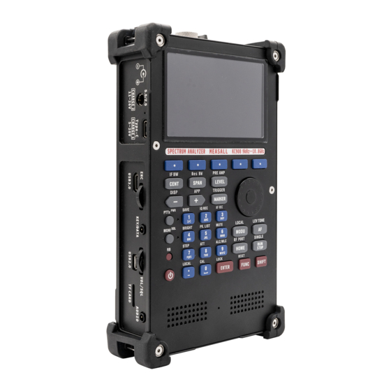
1m from the KC908 in the microwave anechoic chamber. 2.Description of instrument This picture shows each part of KC908. The RF port is at the top of KC908. On the left part is mainly the data port and the knob. Speaker and microphone are at the bottom of front panel. -
Page 10: Top Panel
2.1 Top panel... - Page 11 There are 2 RF ports on the top of KC908, left port is PORT1, right port is PORT2. Both ports support input and output. Two LEDs in the middle of two ports are used as indicators to show witch port is selected.
- Page 12 channel of PORT 1 just has simple 2 band preselector, whose range is below 500MHz and above 500MHz, respectively. Port 1 is mainly used as an output port, it can output full range RF signals, and the amplitude is higher. As for 18.6GHz model, the left port is also used to connect GPS antenna.
- Page 14 While using large size HF antenna, it is recommended to connect a high pass filter with DC grounding outside to protect the KC908. It is suggested that the suppression of frequency below 500KHz is better than 30dB.
-
Page 15: Left Side Panel
12V. It can be directly connected to 12V, 13.8V or 24V automobile batteries. The maximum charging current of 12V charging port can reach 2A, which can fully charge KC908 in about 3 hours. For continuous measurement, 12V charging port should be used for power supply, and the voltage should be 12~18V. -
Page 16: Usb Charging Port
2.2.2 USB charging port In order to reduce the burden of carrying charger, KC908 supports USB charging, user can use ordinary mobile phone charger and "power bank" to charge. USB charging port uses type-C connector, which supports most quick charging protocols. The maximum charging voltage can reach 20V, and the limit current is 3A. -
Page 17: Usb 3.0 Port
2.2.3 USB 3.0 port This port is used to output the high speed IQ signal to host. The program manual show the usage method. 2.2.4 USB-OTG port This is a USB 2.0 standard port that supports OTG, and it's mainly used to control dedicated accessories. -
Page 18: Audio Port
KEY1 and KEY2 are used to connect the telegraph key. While using a manual key it should connect to KEY1 and GND. To use an automatic key user should connect KEY1, KEY2 and GND. The driving voltage for key is usually 1.8V. - Page 19 2.2.7 Knobs KC908 has two knobs on the left side. The upside one is a multifunctional knob, in different menus it has different functions. Such as after RF/CF button has been pressed, this knob is used to switch the frequency. This knob can be...
-
Page 20: Front Panel
Press the knob repeatedly to switch between currently effective audio settings. 2.2.8 TF card slot KC908 support max 32GB TF card, which is used to save the measurement or firmware update. We suggest using high speed TF card if user needs to save the IQ data. - Page 21 The display is divided into few areas, the following is the area of the receiver mode. The styles of other mode are same. Following picture is the spectrum mode...
- Page 22 Avoid using alkaline detergent. If the screen is broken, user needs to send KC908 to our factory to repair. 2.3.2 Keyboard The keyboard has three areas, F1 to F5 are the soft key to operate the soft menu, and the function buttons are used to set and adjust the functions.
- Page 23 For quick operation, The common menu function set to the second layer key, press SHIFT key to access. Following is the first layer of keyboard: CENT Set the central frequency SPAN Set the horizontal scanning width LEV setting the vertical level parameter(REF, gain) MARK Enable marker MODU receiver mode: setting the demodulation parameter Spectrum mode: setting the MAKER...
- Page 24 squelching. The power button is designed to become active after pressing 0.5 second. The “+” “-buttons become active once is short pressed, if hold the “+””-” is held more than 0.5s it will repeat the action. Other button just act once when pressed. For those functions that are commonly used yet hidden in depth inside the menu for the sake of a clear logic, we've prepared shortcuts for them.
- Page 25 IQ REC record the IQ signal, only works in receiver mode. Record bandwidth is relevant to demodulation bandwidth. AF REC record the audio, only works in receiver mode and demodulation turned on. BRIGHT set the screen brightness PK.LIST Turn on the peak list function(in spectrum mode) MUTE mute the demodulation audio STEP...
- Page 26 Swiftly switching squelcher on/off. 2.4 Battery The KC908 uses four 18650 lithium batteries with a limit voltage of 4.2V for each individual and a total capacity about 50Wh. The battery is located in the middle layer and with circuit boards on both sides, it is not swiftly-replaceable, thus spare batteries or chargebanks should be prepared for a long period usage.
- Page 27 RF port, then tighten the screws on the board, connect the cables, turn on the power to confirm everything is working normally, then close the back cover. 2.5 Ports inside KC908...
-
Page 28: Gps Antenna
FUNC-TIME setting, and click sync to GPS. GPS Antenna The left port of KC908 can be used as input port for GPS antenna. A GPS antenna needs to be connected before using GPS functions. After GPS function is enabled, the left port will be locked and it's no longer available to... - Page 29 1575MHz frequency band should be able to receive the signal. For working environments like city, mountain areas, or somewhere with sever blockage, it's advised to use an active antenna. Since the ports of KC908 are not equipped with bias-T, the active antenna should be powered by external power source or battery.
- Page 30 KC908. To know the difference between modes and choose one to get right result. The KC908 can only operate in one of these modes, except in certain special cases. The MODE key is for mode selection, and the mode selection menu is displayed after the key is pressed.
-
Page 31: Horizontal Axis
The various models are just applicable to different needs, making the machine more appropriate for the application scenario. Although based on same hardware, performance may vary slightly due to a preference for driving methods depending on the scenario. 3.1 Spectrometer A spectrometer is an instrument that displays a signal in the frequency domain, and the results displayed are called spectrograms. - Page 32 FFT results. Measuring and stitching take time, and the larger the SPAN, the longer it takes to refresh a screen. Due to the splicing, adjusting the RBW of KC908 to a large value would not obviously speed up the refresh rate.
-
Page 33: Vertical Axis
(which can be generalized to impedance) is determined, then the power, voltage, and current on the load are interdependent, and by measuring one, one can know the other two.The nominal impedance of the KC908 is 50 Ω, so whether the power, voltage, or current is displayed, the amplitude of the signal is correctly represented. -
Page 34: Frequency Setting
Full SPAN, Last SPAN, Step Set and ZeroSpan. The Full SPAN on KC908 is different from conventional spectrometers. In the conventional manner, the machine would scan the full frequency span, which is predictably from 0 to the upper frequency limit. Yet, KC908 would not... - Page 35 alter the central frequency, but just set the SPAN to the max permitted value with the current central frequency. 3.1.4 Amplitude setting LEV is used to set various parameters related to amplitude, such as reference level, vertical scale, attenuation, gain and reference offset. The level value represented by the inscribed line at the top of the spectrum chart is called the reference level (REF), a name inherited from the analog era of oscilloscope display spectrometers, which requires counting the...
- Page 36 The picture below, in which all the filters are neglected, shows the simplified structure of the RF front end. Restricted by the overall architecture, KC908 adopts a high-gain front end design. There are two levels of preamplifier in the front of the frequency mixer or the IF. Below 6GHz, the first level can be set to bypass, offering a maximum gain of 40dB.
- Page 37 in the circuit and the mixer into consideration, the actual maximum gain would be approximately 60dB. The total amount of attenuator available below 6GHz is 50dB. In circumstances with strong signal or severe interference, not only bypass amplifier but also attenuator is needed. The proper amount of gain and attenuation would be selected automatically according to the REF setting.
- Page 38 750MHz~6 0dBm 6~10.8/18.6 5kHz~750 750MHz~6 -10dBm 6~10.8/1 8.6GHz 5kHz~750 750MHz~6 -20dBm 6~10.8/18.6 5kHz~750 750MHz~6 -30dBm 6~10.8/18.6 5kHz~750 750MHz~6 -40dBm 6~10.8/18.6 5kHz~750 -50dBm 750MHz~6 6~10.8/18.6 -50dBm 5kHz~750 -60dBm...
- Page 39 LEV button, ATT for attenuator and AMP for LNA would be displayed on the top-left part on screen respectively for manual setting. KC908 has been tuned for optimal performance while being used with hand-held antenna. Under ideal electromagnetic environment, setting ATT...
- Page 40 and AMP manually should be avoided, whereas under poor electromagnetic environment or using a outdoor antenna, the REF, ATT and AMP settings should be combined properly according to the spectrum. REF is still relevant while using manual setting, because REF is ganged with IF gain. The interference resistance level at highest gain is given in the technical parameter chart.
-
Page 41: Mode Setting
Vice versa, switching AMP off or increasing ATT value cannot reduce the interactive interference within the machine, yet it might even become unneglectable without the amplifer's noise. 3.1.6 Mode Setting Mode setting is different from mode selection. Once a mode in selected, the mode setting menu becomes the top-level menu under that mode. - Page 42 The performance of different window types varies. Taken the fact that it's a custom to adopt gaussian filter into account, KC908 adopts a gaussian window. In this situation, RBW represents an equivalent IF filter's 3dB bandwidth.
- Page 43 SPAN theoretically. In other words, there is a function mapping SPAN and RBW and SPAN is the variable. This fact brings inconvenience to real-world operation, thus KC908 adopts the minimum RBW of current SPAN by default. Also, it's allowed to manually adjust in a limited range. Effectively, this is adjusting FFT points and window shape.
- Page 44 this moment, "represent" needs a definition. This definiton is also known as detection method. For example, auto-peaking means displaying two dots on one column on the screen. One of them is max value and the other is min value. Connect these two dots with a line, and when the marker reads the value, the frequency and amplitude of the max point would be read.
- Page 45 Pic : Four markers in spectrometer. Capable of moving to different tracks and enabling substraction and field strength calculating function. To receiver, this function is meant to switch to receiver mode, and set the marker frequency as the receiving frequency. With auto-peaking function enabled, the marker would stick to the peak spectrum line instantaneously.
- Page 46 (4) Peak Table This function is meant for searching strong signals within spectrum automatically and log them into a table. While the top 100 strong signals have been logged, only 10 of them are to be displayed. Only signals meet the criteria set by the user would be logged. Save table function is meant to save the peak table to the receivers.
- Page 47 The criteria determine whether all the desired signals have found completely and accurately. Those criteria are in peak search setting and there are three options. a. Threshold Equivalent to "squelching". Only signals stronger than this parameter would be logged and it's used to filter those small signals that are not of interest.
- Page 48 b. Frequency Gap Defines the minimum frequency gap between two peaks. Given two peaks whose gap is smaller than this setting, then only the peak appears first or the peak with large peak value would be logged. This setting is meant to prevent logging a wideband signal with multiple peaks as multiple signal.
- Page 49 Defines how many dB lower must the bottom between two peaks be, when compared to the lower peak. If there is no bottom that fits this criterion present between two peaks, KC908 would recognize these two peaks as one signal.
-
Page 50: Port Switching
e. Frequency Rounding Since the deviation of the signal's frequency and the limit of detecting precision, the peak list contains a lot of data with multiple digits of non-zero tails. It's inconvenient because it's not the common interval of like 25kHz or 200kHz. - Page 51 (6) Antenna Gain Antenna gain setting is to determine the total gain of the external antenna system. With a correct setting, the apparatus can calculate the actual field strength within the resolution bandwidth with field strength unit switched to dBμV/m. Note that other field strength unit doesn't work whis way. If the user want to pair with external attenuators and amplifiers, press LEV button and set those parameters in "Amplitude Shift".
- Page 52 For the time being it's accustomed to use VFO to refer to the free frequency adjusting mode.("free" compared to channel mode). For disambiguation, KC908 hereby adopts the latter definition. The machine comes with 2 VFO, VFOA and VFOB. Settings between them are independent, just choose one of them when using.
- Page 53 8.350MHz from 101.7MHz. Following this operation, KC908 would restore demodulation setting to USB with 3KHz bandwidth automatically. The partition of frequency is shown below:...
- Page 54 3.2.2 Channel CH, the acronym for channel, refers to channel mode, yet it's also refered to as MR, memory mode. KC908 is capable of storing 1000 channels, most settings between channels (including port) are independent. But preference settings like volume and display sytle are exceptions.
-
Page 55: Auto Gain Control
In CH mode, although frequency and settings can still be changed freely, it's temporary. In other words, the changed settings would be overridden next time using the same channel unless changes are saved prior to that. What's more, there will not be any segment while adjusting frequency temporarily in CH mode. - Page 56 In spectrometer mode, the combination and consequent value of these amplifiers and attenuators depend on the setting of reference level, and the whole adjustable range of gain can be up to 100dB. In receiver mode, by default the attenuators and amplifiers would adjust themselves automatically according to input.
- Page 57 If the total electric power level ADC receives is too high, KC908 would decrease the gain tentatively until the overload is gone. On the other hand, the gain would increase when the level drops to maintain a relatively high sensitivity.
- Page 58 As a compensation, KC908 allows user to manually specify gain and attenuation and those unspecified parameters will still be adjusted automatically. In harsh electromagnetic environment, it's advised to specify a attenuation of 10dB of higher, do not use the 40dB RF gain(AMP), and leave other settings at auto.
- Page 59 User can distinguish whether it's in auto mode or manual mode by the color of ATT and AMP displayed on the screen. Golden yellow means auto mode. Whenever the gain is adjusted, KC908 would automatically adjust the reading. The actual parameters of amplifiers and attenuators corresponding to...
- Page 60 AGC is 1s. 3.2.5 Level/Field Strength KC908 displays level on the top right corner of the screen. Level indicates the total power within the demodulation bandwidth, which makes it different from the marker on the spectrum. It can be adjusted by pressing MODU button-demodulation-demodulation bandwidth.
- Page 61 Mapping tone to such an large interval can barely reflect any detail. Thus the range must be narrowed and KC908 comes with a range of 80dB. After enabling this function, a proper central point of the level must be selected and set.
- Page 62 If no adjustment has been made within 5 seconds, the knob function returns to volume setting automatically. 3.2.7 Squelcher and Denoiser KC908 comes with a squelching function, which is designed to turn off sound ouput when no signal is present or the present signal is not desired, to avoid making unnecessary noise.
- Page 63 When the level is higher than the threshold sounds are enabled. Level squelcher adopts stagnating-recursive comparison, whose intetval is 2dB by default. The threshold would be displayed with a horizontal green line in the spectrum. Conversational squelcher: Analyze the audio and judge whether the non- noise component is larger, if so, sound would be turned on.
- Page 64 3.3 Simple Signal Source The signal source function is capable of generating equal amplitude, modulated amplitude, modulated frequency, as well as modulated phase signals. Port 2 (on the right side) supports 100MHz-6Ghz while port 1 (on the left side) supports 9kHz-10.8/18.6GHz. Without ALC, the maximum output amplitude varies as the frequency changes.
-
Page 65: Test Preparation
Since that, extra attention should be paid. We recommend using it only for comparison. 4.Test Preparation KC908 is equipped with two RF input/output channels, and it’s capable of testing spectrum and field strength. Preparations are different as for different test. - Page 66 RECEIVER >6GHz 9kHz-500MHz Comparator Amplifier 20dB 500MHz-6GHz 3.5h 9kHz-1GHz 1GHz-6GHz 4.5h Simple signal source@max Signal Source* output amplitude 10.8/18.6GHz 9kHz-500MHz 500MHz-1GHz Network Receiver amplifier 20dB 1GHz-6GHz 3.5h Analyzer 10.8/18.6GHz Idle *Endurance time just for reference. Some functions are optionally-shipped. Be subject to the machine.
- Page 67 For 5V@1A charger, typical time is 15 hours, while 10 hours for 5V@2A charger. Quick charge compatible chargers would probably take less time. KC908 would measure the current and voltage to analyze the charger and subsequently adjust the charging current. Yet, even with the exact same parameters, two different chargers can possibly perform quite differently.
- Page 68 KC908 adopts a RF socket with a inner diameter of 2.92mm, which is compatible with SMA standard, and the actual cutoff frequency can reach 40GHz. Although the socket has been strictly reinforced, it cannot withstand massive force due to its structure, inherently.
-
Page 69: Outdoor Antenna
(5) Chose high quality product. Rotate the rotating shell of the connecting part but not the entire body while installation. Press the main body of the socket and tighten the screw to make the surface connect seamlessly. The connector must be rotated until tightened before usage, as any shaking could damage the core, even loosening the connection between the socket and the motherboard. - Page 70 For hand-held antennas that are to be used in a mobile manner, select those with desired frequency and gain. Besides, the distance between the antenna and KC908 as well as the force exerted on the RF port should be taken into account.
- Page 71 (spring anatennas). (3) DO NOT point the transmitting/receiving direction of the antenna towards the apparatus. Instead, this direction should be paralleled to KC908, or just keep a distance between the antenna and the apparatus. As the pics...
- Page 73 Always avoid winding the antenna with user's body, as it may hurt the user while the user is running and damage the connector. (6) To measure the field strength, prepare an antenna whose gain is already known, and input its gain to KC908. 4.4 Holding and Carrying...
- Page 74 KC908 is designed to be operated with both hands. Hold the machine with both hands and use thumbs to operate the keyboard. To operate the rotary knob, hold the right part of the machine with right hand and rotate the knob with lefr thumb.
- Page 75 For running situations, we recommend using the lower mounting points as well as adopting a sling-across-shoulder position. KC908 comes with ZERO ability of water-proof. What's more, even with a silicon case, the situation can barely be improved. In water-related scenarios, the apparatus must be sealed with dedicated water-proof plastic bag in advance.
- Page 76 (2) Pay attention to low-frequency electromagnetic induction when a relatively long antenna is installed, particularly a short wave antenna. resistant power of KC908 drops when the frequency is below 1MHz, above 0dBm input is strong enough to possibly cause damage at 9KHz.
- Page 77 It would typically take half an hour for a person with basic RF knowledge to get the hang of KC908. One thing we take for granted is that KC908's users are all professional, thus the main focus is the counter-intuitive part. As for the menu structure,...
-
Page 78: Boot And Shutdown
5.1 Boot and Shutdown The POWER button on the lower left part of the keyboard is used to boot/shutdown, while the RB button is used for hard-reboot. The POWER button would only be functional after being pressed for more than half a second. Parameters would be stored before each shutdown and restored after each boot. -
Page 79: Typical Operations
5.2 Typical Operations 5.2.1 Primary Functions KC908 comes with 3 major operating logic other than RUN/STOP buttons. (1) Menu-select-input(or setting)-confirm(or cancel) Take setting the central frequency as an example. Press RF/CF button first and the frequency setting menu shows. There are 3 options, central frequency, scanning width and resolution bandwidth. -
Page 80: Home Button
Example: SHIFT+LEV to adjust the marker menu swiftly. (2) Serve as a quick switch between on/off or parameters. Example: SHIFT+4 to switch the background lighting level. (Press repeatedly to circulate the setting among 10%, 30%, 70% and 100%.) 5.2.3 Mistaken Input With a mistaken input that involves number, don't press ENTER and reactivate input again, the value would be restored to original setting. -
Page 81: Func Button
HOME button repeatedly and it would circulate between these two mentioned menus. 5.2.5 FUNC button To be precise, this button should be CONFIG, as it's meant for system configurations. We call it FUNC simply to respect the custom. After pressing the FUNC button the setting menu appears, to navigate the marker in this menu, use left/right key (+,-key). - Page 82 knob. One beep for volume adjusting, two beeps for squelching, three beeps for level tone central point adjusting. an interval of 5 seconds without input would restore the knob's funtion to volume controlling. 5.2.7 Locking Press SHIFT+ENTER to lock or unlock the machine to prevent accidental unwanted operation.
- Page 83 Rebooting the machine using power buton doesn't change locking config, while rebooting using RB button does. 5.2.8 Custom Parameters To provide extra convenience, some parameters come with an option of custom value. Take demodulation bandwidth as an example, in addition to those typical options among 150Hz-300KHz, this parameter can potentially be adjusted continuously.
- Page 84 (1) Make it clear what to measure. Like the frequency, bandwidth and modulation method of the tested signal. For example, modulated stereo broadcasting, modulation method is FM and the typical bandwidth is 250kHz. Different measuring purposes may be corresponding to different sets of parameters.
- Page 85 Connect the antenna to the desired port. (3) Press and hold POWER button for half a second, KC908 beeps and boots. Next, press MODE button to switch the machine into Receiver Mode. (4) Check whether the port being used is the desired one. (Right port in this case).
- Page 86 (5) If the apparatus is not running yet, press RUN/STOP button to initiate when desire. The three conditions displayed on the upper part of the screen should be adjusted to be exact the same as the pic below. (6) Check the frequency. (F, settings that could be adjusted often displayed as white over a cyan background).
- Page 87 If the peak list is stored in spectrometer mode in advance, receiver mode can directly access those data by selecting Peak List in the pic above, just like the pic below shows. No matter where the frequency comes from, channel or peak list, user should push it to VFO if user wants to adjust the parameters temporarily.
- Page 88 (8) Observe the position of the curve on the screen, if its upper part exceeds the top of the screen, simply increase REF. If the curve is miles away from the top of the screen, or its bottom part exceeds the screen bottom, the REF should be decreased.
- Page 89 the narrower the better. Nonetheless, extremely low background noise in a narrow spectrum exposes the residual responses of the apparatus (also known as dots), even making them dazzling. (10) Normally the spectrum adopts peak detector, and the setting entrance locates in the second page of the mode main menu. This parameter does not worth attention unless the user is paticular with spectrum, like reading number using the marker.
- Page 90 demodulating bandwidth can be adjusted if the tested signal is much wider/narrower than the highlighted area. In MODU menu, DETECTOR defines the way level meter detects the signals. This setting can be neglected if the user just want to take a glance of the level/field strength.
- Page 91 Demodulation parameters are displayed on the information bar on the middle on the screen. (14) Adjust the antenna , find out the position and direction where field strength maximizes and watch the reading on the screen. For screenshots, press SHIFT+1. (15) Accumulating function, which is an optional component, can be used if the standard of the test demands.
- Page 92 However, the sensitivity of the cymometer is relatively low and it's vulnerable to interference produced by emissive sources out of interest (like mobile phone base station). Fortunately, the spectrum mode of KC908 offers a performance right on the sweet spot of speed, sensitivity, anti- interference ability as well as frequency accuracy, in other words, an ideal comprehensive performance.
- Page 93 500MHz, thus CENTER could be set to 400MHz, and SPAN set to 200MHz. Use START, STOP option to spcify 300-500MHz also works. (2) Since it's from neighbourhood, the signal tends to be strong. Lower the sensitivity by pressing LEV button and set REF to -10dBm or higher. (3) Use marker function if manual observation is scheduled to find the emission frequency.
- Page 94 would still be running in the background. Press HIDDEN again to show the hidden table. (7) If necessary, parameters such as FREQ GAP, LEV GAP and Threshold, etc, can be set in SEARCH SET menu. Tips are, set FREQ GAP to half of channel gap like 12.5KHz, set LEV GAP to 5dB or above, set Threshold to - 30dBm.
- Page 95 (8) After a period of time, check the PEAK TABLE and estimate whether the signal of interest is logged. If the answer is yes, press the save button on the soft menu to save the table. The table will be saved to TF card (if equipped) as well as the VFO temporary frequency list.
- Page 96 6.1 Why is the reading of the spectrum inconsistent with the field intensity in receiving mode? For KC908, the value of LEVEL (field intensity) is the total energy within the whole bandwith of demodulation. The SPECTRUM is showing how those energy distributes in the frequency domain.
- Page 97 For wide-band signals, the wider the resolution bandwidth or demodulation bandwidth is set, the larger the readout will be. Also, the detection method of SPECTRUM and LEVEL can be set separately. If then, the readout will be different. 6.2 Why the squelch can be turned on when the frequency spectrum is lower than the threshold of the squelch level? The reason is the same as 6.1.
- Page 98 6.3 Why the refresh rate is slow when SPAN is set to narrow? The spectral resolution of KC908 is tied to SPAN. The narrower the SPAN, the smaller the resolution(RBW). For example, when SPAN=1KHz, the resolution is 1Hz. It takes time to measure the frequency of 1 Hz, and the period of the 1 Hz is 1 second.
- Page 99 6.4 Where does the image interference appear? In the range of 0~750MHz(0-500MHz for left port) and above 6GHz, there may be two kinds of image interference, namely the image interference of the first mixer and the second image interference. For 10.8GHz model, the frequency of the 1st IF is about 2.65 GHz, and the image interference point is about 5.3 GHz away from the observation frequency point.
- Page 100 The 18.6GHz model adopts tracking preselector, protecting all its passband from image interference frequencies, thus it can offer at least 50dB image suppression. You can pre-determine whether the signal is true or fake by adjusting the center frequency and observe the direction and speed of spectral line movement.
- Page 101 decreasing the input signal, lowering IF gain and changing central frequency(CENT) would probably help. The pic below shows a relative severe situation of second image interference, where the image suppression is approximately 58dB. By shifting central frequency, the interference could be lowered to -65dBc. Since the second image is very close to tested signal, user needs to keep in mind not to confuse it with the spurious divergence.
- Page 102 This is a compromise between high sensitivity and anti- interference ability. For details, see the index of third-order intercept point. KC908 will generate EMI itself. These radiation will leak into the receiver from the inside of the instrument, just a small amount.The resulting residual response is usually below -100dBm.
- Page 103 While using a narrower SPAN (such as receiving mode), the noise floor is often as low as -130~-140dBm, and the internal leakage interference will become easy to notice. Considering the size of KC908 is too small to isolate, it is recommended to keep the antenna away from the body of instrument to reduce interference.
- Page 104 In KC908, the analog bandwidth is wider than SPAN, usually around 50MHz. In other words, signals that are not visible on the spectrum can also cause overload. After overload occurs,the instrument usually will displays a prompt, but it is not quite reliable.
- Page 105 Meanwhile, the high-speed digital circuits also needs enormous power resources, these factors would lead to heat generation too. The minimum power consumption of KC908 is about 10 watts, and typical power consumption is 12W, while the peak power consumption is 15W. When...
-
Page 106: Frequency Range
energy stored in the battery. At this time, the shell will be very hot. The temperature of the shell will increase 20~35℃ with these heat. In summer, the surface temperature can reach 70℃, which may cause burns. In winter, it can be used as a "hand warmer". - Page 107 Port Typical Note Spectrometer, receiver effective(note 9kHz 6GHz port 1, left 6GHz setable 9kHz 10.8/18.6GHz effective port 2, right 10.8/18.6GHz setable Comparator(note 2) Both ports 1MHz 6GHz effective used 6GHz setable Signal source 10kHz 10.8/18.6GHz effective port 1, left 10.8/18.6GHz setable 100MHz 6GHz...
-
Page 108: Resolution Bandwidth
7.2 Spectrum Width(SPAN) port typical note spectrometer 1kHz 5.995GHz effective port 1, left 1kHz 6GHz setable 1kHz 10.8/18.6GHz effective port 2, right 1kHz 10.8/18.6GHz setab receiver 1kHz 15MHz comparator 1kHz 10MHz 7.3 Bandwidth 7.3.1 Resolution Bandwidth Resolution bandwidth is relevant to spectrum width(SPAN). The minimum resolution bandwidth after adjusting SPAN is 1Hz, while the maximum value is 2.048MHz(the max adjustable value is 8MHz, not guaranteed). -
Page 109: Real-Time Bandwidth
7.3.2 Real-time Bandwidth When displayed locally, the real-time bandwidth is 15MHz. The spectrum of receiver only works in real-time bandwidth's range, and SPAN is continuously adjustable. When spectrometer's SPAN is set to less than 15MHz, it's real-time spectrum, while when SPAN is over 15MHz, it becomes spliced spectrum. -
Page 110: Audio Bandwidth
wriiten to TF card at a relatively low speed, with a max recording time limitation of 90 seconds. 7.3.5 Audio Bandwidth No matter how the demodulation bandwidth is set, the max audio bandwidth are always 15kHz. Audio bandwidth could be set within a range of 150Hz-15kHz, and it's continuously adjustable with 3 effective digits. - Page 111 calibration range Note: Tested after 10-min preheat. all the temperatures are ambient temperature. The frequency of the machine can be calibrated in FUNC-System Settings, thus short-term stability is more important. 7.5 Amplitude Note/Conditio Item Typical Spectrometer, receiver -100dBm 20dBm(note 1) effective REF range -100dBm...
- Page 112 ±2dB 1MHz-6GHz left port uncertain 10.8/18.6GHz right port ±3dB 100MHz-6Ghz max output 13dBm left port level -3dBm right port Note: 1. When frequency is above 10MHz. With frequency between 1-10MHz, 10dBm. Frequency <=1MHz, 0dBm. Ambient temperature 25℃, after 10min preheat. Non-official function, just for reference.
- Page 113 1MHz -108 -105 1kHz -105 -102 10kHz -115 -110 751MHz 100kHz -113 -110 1MHz -120 -105 1kHz -100 10kHz -110 -103 1GHz 100kHz -107 -105 1MHz -117 -113 1kHz 10kHz 4GHz 100kHz 1MHz -105 -100 1kHz 10kHz 10GHz 100kHz 1MHz -106 -100 Note: 1.
- Page 114 7.7 Anti-interference Ability Item Condition Typical Note 9kHz-3MHz -90dBm REF=-70dBm, 3MHz-35MHz -110dBm -100dBm others at auto. Residual Turning off 35-500MHz -120dBm -105dBm Response AMP manually 500MHz-6GHz -100dBm -90dBm (port not would increase connected) the residual -110dBm -100dBm 10.8/18.6GHz response. 5kHz-35kHz -90dBm Residual Tested in the...
- Page 115 carrier=- response not 43dBm included 5kHz-6GHz, Image incoming Refer to 60dBc 35dBc suppression carrier 6dB Chapter 5.4 lower than REF AMP:40, ATT:0 -29dBm IF part not AMP:20, ATT:0 7dBm included. AMP:20, 1MHz-500MHz 35dBm ATT:30 AMP:40, ATT:0 -3dBm Front-end IF part not AMP:20, ATT:0 18dBm third-order...
- Page 116 point with max AMP:20, included, 14dBm IF gain ATT:30 REF<-60dBm. AMP:40, ATT:0 -40dBm 500MHz-6GHz, AMP:20, ATT:0 -18dBm IF included AMP:20, 10dBm REF<-60dBm. ATT:30 AMP:0, ATT:20 -16dBm AMP:30, 10.8/18.6GHz, 12dBm REF<-60dBm. ATT:20 9kHz-35MHz, REF=-70dBm interference 10dBm (achieved max above 55MHz gain), others at 35MHz- auto (AMP40).
- Page 117 distance 100MHz 6-18.6GHz(18.6 model), -13dBm distance 100MHz 1MHz- REF=20dBm(mi 500MHz, bigger than nimum gain), distance 23dBm others at 100MHz auto(AMP0), 500MHz-6GHz, bigger than both ports, distance 23dBm interference 100MHz level making 6-18.6GHz, bigger than 0dBm signal distance level drop 6dB. 23dBm 100MHz With only one strong interference, usually at REF+6dB, no...
- Page 118 For interference outside this range, refer to remote blocking level. <=500MHz or -40dBm >6Ghz LO Leakage 500MHz-6GHz -100dBm 7.8 Speed(note 1) Item Condition Typical Note 5kHz-500MHz 2ms/pt 3ms/pt The gap 500MHz-6GHz 10ms/pt 15ms/pt between switching Tuning speed frequency and 6-10.8/18.6GHz 2ms/pt 3ms/pt obtaining...
- Page 119 Time resolution of 100Lps(10ms) 0.5s/div waterfall chart reading refresh 0.05s speed discover SPAN=15MHz. Capturing time signals Smaller the in real-time SPAN, longer measure bandwidth the capturing 210us accurately time. From pressing Booting time to operatable From pressing Shutdown time to fully shutdown Squelcher 10ms...
- Page 120 3MHz-500MHz -162dBm/Hz -155dBm/Hz All refer to 500MHz-6GHz -163dBm/Hz -153dBm/Hz with max gain. Normalized REF=-70dBm, 6-10.8GHz -160dBm/Hz -147dBm/Hz noise others at auto. floor(note 2) Average value 6-18.6GHz -150dBm/Hz -140dBm/Hz detection mode. demodulation 3MHz-500MHz 0.3uV 12kHz BW (note 3) 1MHz-500MHz 9kHz BW demodulation 1MHz-500MHz 0.15uV...
- Page 121 1kHz single tone, FM modulation frequency deviation is 3kHz, AM modulation 80% depth. CW as non-modulated carrier. PRE AMP, AGC turned on. Parameter Typical Note Port DC voltage RF port withstand ability 5.5/2.5 Power External DC 10.5V Jack power supply 4.9V TYPE-C port 5.5/2.5 Power...
- Page 122 Battery only. Idle. Shutdown Power 500uW Battery only. Consumption Storage Time With initial battery voltage of with power 7.5V Speaker Power Audio LineOut Impedance of Power 1.5W 4Ohm MIC Input Impedance of Sensitivity 50mV 600 Ohm Internal Barometer 300 hPa 1100 hPa Range Internal...
- Page 123 Internal After Magnetic Compass 5 degrees Uncertainty calibration Nomal range ℃ ℃ Permitted range ℃ 50℃ Short-term ℃ 70℃ storage 0℃ 35℃ Long-term storage Ambient The minimum Temperature acceptable temperature The core temperature of the mentioned above is machine must be lower than determined by the minimum the upper limit of the battery usable temperature of the...
- Page 124 (Damaged appearance yet perfectly With a protective functional) 1.2m case 20Hz@5G@30 Aseismatic min, any Ability direction Main body only, 188x110x39 with stick-out part Size 177x102x32 Without stick-out part Main body with Net Weight 901g battery inside. Package With stock Weight protective case...
Need help?
Do you have a question about the KC908 and is the answer not in the manual?
Questions and answers