Advertisement
Quick Links
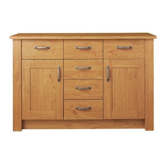
Ohio - 6+2 Sideboard
Assembly Instructions -
Dimensions
Width - 120cm
Depth - 39.5cm
Height - 78cm
Important -
Please read these instructions fully before starting assembly
If you need help or have damaged or missing parts, call the Customer Helpline: 03456 400800
Please keep for future reference
314/7128
MADE IN
BRITAIN
Issue 3 - 12/03/15
Advertisement

Related Manuals for Argos Ohio 6+2 Sideboard 314/7128


Summary of Contents for Argos Ohio 6+2 Sideboard 314/7128
- Page 1 Ohio - 6+2 Sideboard Assembly Instructions - 314/7128 Please keep for future reference Dimensions Width - 120cm Depth - 39.5cm MADE IN Height - 78cm BRITAIN Important - Please read these instructions fully before starting assembly If you need help or have damaged or missing parts, call the Customer Helpline: 03456 400800 Issue 3 - 12/03/15...
-
Page 2: Care And Maintenance
Safety and Care Advice Important - Please read these instructions fully before starting assembly • Warning: This unit weighs • Make sure you have enough • We do not approximately 43kgs. space to layout the parts before recommend the Please lift with care. starting. - Page 3 If you have damaged or missing components, call the Components - Panels Customer Helpline: 03456 400800 quoting the reference numbers below Please check you have all the panels listed below Base (D1811A) (D1814B) (1200 x 395mm) (1016 x 350mm) Plinth (D1816A) (1016 x 95mm) Fascia...
- Page 4 If you have damaged or missing components, call the Components - Fittings Customer Helpline: 03456 400800 quoting the reference numbers below Please check you have all the fittings listed below Note: The quantities below are the correct amount to complete the assembly. In some cases more fittings may be supplied than are required.
- Page 5 If you have damaged or missing components, call the Assembly Instructions Customer Helpline: 03456 400800 quoting the reference numbers below Step 1 Note: The left drawer front has a shallow identification mark. Prepare the drawer fronts Screw 2 metal dowels into the holes shown on the left drawer front the right drawer front...
- Page 6 Assembly Instructions Step 4 Fit the drawer bases Slide the large drawer base down the grooves in the drawer sides down into the groove in the left drawer front and right drawer front 10 11 Slide the small drawer base down the grooves in the drawer sides...
- Page 7 Assembly Instructions Step 6 Attach the handles Attach a handle each drawer front using 2 screws Step 7 Fit the wedgefixes Turn all of the drawer assemblies over and slide 2 wedgefixes into the front and back grooves, as shown, and tighten up the screws.
- Page 8 Assembly Instructions Step 9 Prepare the 2 fascias 10mm Left fascia - holes nearest this side Check that the holes are in the same place as the diagrams, as one will be the left fascia and one will be the right fascia. Screw 3 metal dowels into each of the 2 fascias Tap a wooden dowel...
- Page 9 Assembly Instructions Step 11 Join the left side to the left fascia panel Push the left side down onto the left fascia Dowel panel this end Left fascia Use a screwdriver to tighten the 3 large locking nuts fitted to the left side Note: Turn the large locking nuts...
- Page 10 Assembly Instructions Step 13 Join the right side to the right fascia panel Push the right side down onto the right fascia panel Dowel this end Right fascia Use a screwdriver to tighten the 3 large locking nuts fitted to the right side Note: Turn the large locking nuts...
- Page 11 Assembly Instructions Step 14 screw screw screw Finish preparing the left side Fit a runner the left side The 1st screw uses the 1st hole in from the front of the runner. The 2nd and 3rd screws use the holes that line up with the other panel holes.
-
Page 12: Right Side
Assembly Instructions Step 15 screw screw screw Finish preparing the right side Fit a runner the right side The 1st screw uses the 1st hole in from the front of the runner. The 2nd and 3rd screws use the holes that line up with the other panel holes. - Page 13 Assembly Instructions Step 17 Fit the base Push the base onto the right side Use a screwdriver to tighten the 2 large locking nuts fitted to p l a the base i n c h i p a r d s u r f a c Finished...
- Page 14 Assembly Instructions Step 20 Fit the left side Push the left side onto the assembly. Use a screwdriver to tighten the 3 large locking nuts fitted to the base and plinth Step 21 Fit the 5 plastic nails Tap 2 plastic nails into the bottom edge of each of the sides and 1 into the centre...
- Page 15 Assembly Instructions Step 23 screw screw screw Prepare the left divider Fit a runner the divider The 1st screw uses the 1sthole in from the front of the runner. The 2nd and 3rd screws use the holes that line up with the other panel holes.
- Page 16 Assembly Instructions Step 24 screw screw screw Prepare the right divider Fit 4 runners the divider The 1st screw uses the 1st hole in from the front of the runner. The 2nd and 3rd screws use the holes that line up with the other panel holes.
- Page 17 Assembly Instructions Step 25 Fit the dividers Carefully stand the unit up for this step. Push the 2 dividers down onto the base Warning: The unit is heavy. Lift with care. Finished front edge Step 26 Fit the top Push the top down onto the assembly.
- Page 18 Assembly Instructions Step 27 The measurement from top corner X to bottom corner X must be equal to the measurement from top corner Y to bottom corner Y Fit the back Lay the unit back down for this step. Square up the unit by making sure that measurement x to x equals y to y.
- Page 19 Assembly Instructions Step 29 Note: The left drawer front has a small identification hole. Fit the drawers Please refer back to Step 1. Slide the wheels of the runners fitted to the drawers, over the wheels of the runners fitted to the side panels and push the drawers into position.
- Page 20 Assembly Instructions Step 31 Fit the shelves Lower the 2 shelves down onto the shelf studs Step 32 Prepare the 2 doors Push fit 2 hinges into each of the 2 doors Secure each hinge with 2 screws Note: Before securing with the screws, make sure that the hinges are positioned at 90 degrees...
- Page 21 Assembly Instructions Step 33 IMPORTANT Carefully choose which 2 holes Drill 2 handle holes in each of the doors you need to drill in each door Important: Please follow these instructions ONLY drill these carefully. 2 holes in 1 door Lay the 2 doors down onto a smooth surface.
- Page 22 Assembly Instructions Step 34 Fit doors and handles Note: The easiest way to attach each door to fit the top hinge first, then align and fit the other hinges. Push the hinge onto the front part of the hinge plate The recess at the bottom of screw B goes into the slot in the hinge plate.
- Page 23 Assembly Instructions Step 35 Adjust the doors if needed Before adjusting the doors, use a spirit level to check the base (or top) of the unit is level, front-to-back and side-to-side in the 3 positions shown. Use suitable packing pieces (not supplied) to make the unit level BEFORE making any adjustment to the hinges,...
- Page 24 Lift with care. If you need help or have damaged or missing parts, call the Customer Helpline: 03456 400800 and quote the reference numbers on the component pages. Argos Ltd, 489-499 Avebury Boulevard, Central Milton Keynes, MK9 2NW ALR3081...
Need help?
Do you have a question about the Ohio 6+2 Sideboard 314/7128 and is the answer not in the manual?
Questions and answers