Table of Contents

Subscribe to Our Youtube Channel
Related Manuals for Barmesa Pumps KTM Series


Summary of Contents for Barmesa Pumps KTM Series
- Page 1 Installation, Operation & Maintenance Manual Submersible Dewatering Pumps KTM series 2 - 20 HP @ 3450 RPM barmesapumps.com IMPORTANT! - Read all instructions in this manual before operating or servicing a pump. Last update: 09/21/2020...
-
Page 2: General Safety Information
Model Number, Serial, Amps, i n t e n d e d f o r u s e i n Voltage, Phase and HP from pump IMPORTANT! - Barmesa Pumps is not swimming pools or water name plate for the future reference. -
Page 3: Specifications
Specifications DISCHARGE: 2", 3" & 4" NPT, vertical for hose coupling, cast iron ASTM A-48 class 30. Includes a discharge adapter for NPT threads. LIQUID TEMPERATURE: 104 °F (40 °C) max. UPPER COVER: Cast iron ASTM A-48 class 30. PUMP BODY: Cast iron ASTM A-48 class 30. - Page 4 Dimensional drawings 2KTM201 Ø1.97 7.48 9.25 C.W.L. Dimensions in inches. C.W.L.: continuous running water level. barmesapumps.com 2KTM203 2KTM204 Ø1.97 6.81 9.25 C.W.L. Dimensions in inches. C.W.L.: continuous running water level.
- Page 5 Dimensional drawings 2KTM303 2KTM304 Ø1.97 6.81 9.25 C.W.L. Dimensions in inches. C.W.L.: continuous running water level. barmesapumps.com 3KTM503 3KTM504 Ø3.15 8.18 Ø11.14 C.W.L. Dimensions in inches. C.W.L.: continuous running water level.
- Page 6 Dimensional drawings 3KTM753 3KTM754 Ø3.15 8.18 11.14 C.W.L. Dimensions in inches. C.W.L.: continuous running water level. barmesapumps.com 4KTM1003 4KTM1004 Ø3.93 9.44 C.W.L. Dimensions in inches. C.W.L.: continuous running water level.
- Page 7 Dimensional drawings 4KTM1503 4KTM1504 Ø3.93 14.68 C.W.L. Dimensions in inches. C.W.L.: continuous running water level. barmesapumps.com 4KTM2004 Ø3.93 14.68 C.W.L. Dimensions in inches. C.W.L.: continuous running water level.
-
Page 8: Electrical Hazard
1. Introduction Purpose of this manual The purpose of this manual is to provide necessary information for: Ÿ Installation Ÿ Operation Ÿ Maintenance CAUTION Read this manual carefully before installing and using the product. Improper use of the product can cause personal injury and damage to property, and may void the warranty. - Page 9 These are examples of other categories that can occur, they fall under the ordinary hazard levels and may use complementing symbols: Ÿ Crush hazard Ÿ Cutting hazard Ÿ Arc flash hazard 1.2 Product warranty Coverage BARMESA undertakes to remedy the following faults in products sold by the manufacturer under the following conditions: Ÿ...
- Page 10 1.3 Safety WARNING Ÿ The operator must be aware of safety precautions to prevent physical injury. Ÿ Any pressure-containing device can explode, rupture or discharge its contents if it is over-pressurized. Take all necessary measures to avoid over-pressurization. Ÿ Operating, installing or maintaining the unit in any way that is not covered in this manual could cause death, serious personal injury, or damage to the equipment.
- Page 11 Wash the skin and eyes Follow these procedures for chemicals or hazardous fluids that have come into contact with your eyes or your skin: Condition Action Chemicals or 1. Hold your eyelids apart forcibly with your fingers. hazardous fluids 2. Rinse the eyes with eyewash or running water for at least 15 min. in eyes 3.
-
Page 12: Product Description
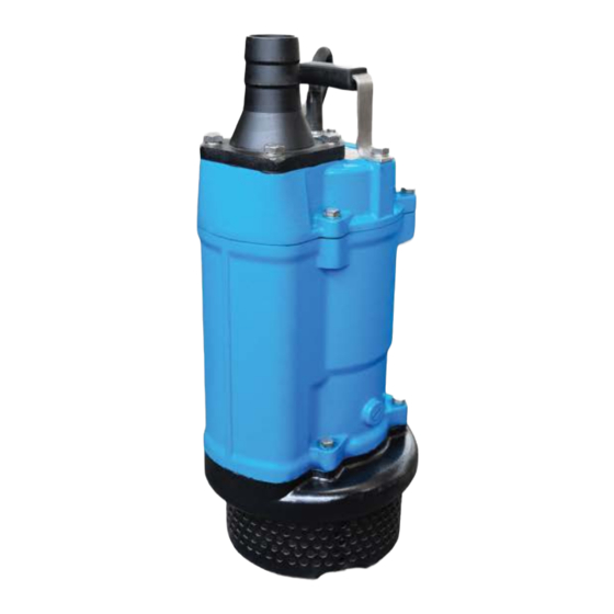
2. Product description 2.1 Pump design FLUID TYPE / TEMPERATURE Work drainage and sand carrying / 32 - 104 °F IMPELLER Open PUMP SHAFT SEAL Double mechanical seal BEARING Sealed ball bearing TYPE, POLES Dry type submersible induction motor, 2 poles INSULATION Class F MOTOR PROTECTOR... - Page 13 2.4 Pump parts names Discharge outlet Cable Hose coupling Handle barmesapumps.com Mechanical seal Shaft sleeve Seal plate Pump body Inlet plate Impeller Strainer NOTE: This diagram shows the part layout of a typical model. The external appearance and the internal construction may vary slightly, depending on your particular model.
- Page 14 2.5 Technical data and function Actuation Recovery Category Recovery mode (s) value time (s) time (s) Manually recovery (manually Phase loss — — turn off the power, correct and turn on the power). Double Manually recovery (manually Impeller jam — rated turn off the power, correct current...
-
Page 15: Prior To Use
Control automático El proceso se repite Pump continues to When the water Pump stops in about When the water level run whit the electric surface falls below one minute after the rises to contact the If the water capacity of the pit is small, probe remains the electric probe, water level falls. -
Page 16: Installation
4. Installation DANGER Disconnect and lock out electrical power before installing or servicing the unit. WARNING Ÿ Do not install the starter equipment in an explosive zone unless it is explosion-proof rated. Ÿ Make sure that the unit cannot roll or fall over and injure people or damage property. WARNING Electrical shock hazard. - Page 17 4.1 Preparation for installation Listed below are tools and instruments that are needed to install the submersible pump for general dewatering purpose: AC voltmeter AC ammeter Insulation resistance tester (megger tester) (tester) (clamp) Wrenches for fastening Wrenches for connecting the power supply bolts and nuts (a screwdriver or a box wrench) Pre-installation check...
- Page 18 3. Handle the pump carefully. When suspending the pump to raise or to lower it, attach a wire rope or a chain to the pump's handle. 4. Install the pump only in an area that can maintain a proper water level. NOTE For details on the water level necessary for pump operation, refer to the section on 'Water Level During Operation"...
- Page 19 CAUTION If an excessive amount of sediment is drawn into the pump, it may cause the pump to wear, which can lead to current leakage or electrical shock. NOTE Appropriate piping materials must be provided by the user. Piping materials are not included with the product.
- Page 20 4.4 Grounding ELECTRICAL HAZARD Ÿ You must ground all electrical equipment. This applies to the pump equipment, the driver and any monitoring equipment. Test the ground lead to verify that it is connected correctly. Ÿ If the motor cable is jerked loose by mistake, the ground conductor should be the last conductor to come loose from its terminal.
- Page 21 CAUTION Ÿ If the cable must be extended, use an extension cable with the same or larger core size as that of the cable that is provided with the pump. Using a cable of proper size will prevent the motor from attaining its full potential or may cause the cable to overheat, which may lead to fire, current leakage or electrical shock.
-
Page 22: Operation
Electric circuit diagrams Three phase (1) Water level control (2) A₁ A₂ Circle thermal protector Coil 5. Operation Precautions DANGER If you need to work on the pump, make sure that it is isolated from the power supply and cannot be energized. - Page 23 1. Once again, check the nameplate of the pump to verify that its voltage and frequency are correct. 2. Check the wiring, power supply voltage, the capacity of the ground leakage circuit breaker and the insulation resistance of the motor. NOTICE Insulation resistance reference value is ≥...
- Page 24 How to verify the correct pump rotation Ÿ By looking at the impeller. The rotation of the impeller should be counter-clockwise as shown in the figure (1). Ÿ By looking from the top of the pump. Since the impeller cannot be seen, the best way to chek the rotation is to check the kick-back motion of the pump when the pump just starts.
- Page 25 Ÿ Do not insert your finger or a stick into the pump's inlet opening. Doing so may cause injury, electrical shock, short, or fire. Ÿ When the pump is not used for a long time, make sure that the power supply (such as a breaker) is properly disconnected.
-
Page 26: Maintenance And Inspection
WARNING A b-contact miniature protector is adopted, which is normally "closed" and goes to "open" upon overheating. To protect the motor from current surges, be sure to install a motor breaker, thermal relay or similar device in the external starting console or control panel. 5.5 Water level during operation Pay attention to the water level during the pump operation. - Page 27 Make sure that you follow these requirements: Ÿ Check the explosion risk before you weld or use electrical hand tools. Ÿ Allow all system and pump components to cool before you handle them. Ÿ Make sure that the product and its components have been thoroughly cleaned. Ÿ...
- Page 28 Interval Inspection item Overhaul Ÿ The pump must be overhauled even if the pump appears normal during operation. The pump may need to be overhauled earlier if Once every it is used continuously or repeatedly. 2 to 5 years Note: Contact the dealer from whom you purchased the equipment to overhaul the pump.
- Page 29 The oil volume for the models which are not included in the tables: about 80% of the total oil cylinder capacity (theoretically, the oil level should cover the mating ring). The parts listed below are dispensable items. As a rule of thumb, use the replacement period as a guide to replacing these parts.
- Page 30 Disassembly procedure for 2 - 3 HP NOTE Before disassembling, be sure to drain the oil from the pump. Models 2 & 3 HP have the same construction. However, models 5 & 7.5 HP are constructed without shaft sleeve. 1. Removing the strainer stand. Remove the hexagonal nut and the plain washer from the bottom and remove the strainer stand from the pump.
- Page 31 Disassembly procedure for 5 - 20 HP NOTE Before disassembling, be sure to drain the oil from the pump. 1. Removing the bottom plate and the strainer. After removing the hexagonal nut and the plain washer from the bottom, remove the bottom plate and the strainer from the pump. 2.
- Page 32 Reassembly procedure 1. The reassembly procedure is the reverse sequence of disassembly. NOTE Ÿ After completing reassembly, do not forget to pour the specified amount of oil into the pump. Ÿ The gaskets and o-rings must be replaced with new parts. Also replace any parts that are worm or damaged.
-
Page 33: Troubleshooting
Troubleshooting Symptom Cause Countermeasure Contact the electric power company or an electrical No power is supplied (i.e. power outage). repair shop. Pump fails to Open circuit or poor connection of the start. Check if there is an open circuit in the cable or wiring. cable. - Page 34 Sectional view drawing & parts list 2KTM201 barmesapumps.com Item no. Part name Material Item no. Part name Material House coupling Cast iron Stator Handle Rubber & steel Rotor Shaft: AISI 420 SS Upper cover Cast iron Bearing Ball bearing Upper support Cast iron Bearing Ball bearing...
- Page 35 Vista seccionada y lista de partes 2KTM203 2KTM204 barmesapumps.com Item no. Part name Material Item no. Part name Material House coupling Cast iron Stator Handle Rubber & steel Rotor Shaft: AISI 420 SS Upper cover Cast iron Bearing Ball bearing Motor body Cast iron Bearing...
- Page 36 Vista seccionada y lista de partes 2KTM303 2KTM304 barmesapumps.com Item no. Part name Material Item no. Part name Material House coupling Cast iron Stator Handle Rubber & steel Rotor Shaft: AISI 420 SS Upper cover Cast iron Bearing Ball bearing Motor body Cast iron Bearing...
- Page 37 Vista seccionada y lista de partes 3KTM503 3KTM504 barmesapumps.com Item no. Part name Material Item no. Part name Material House coupling Cast iron Stator Handle Rubber & steel Rotor Shaft: AISI 420 SS Terminal box Cast iron Bearing Ball bearing Upper cover Cast iron Bearing...
- Page 38 Vista seccionada y lista de partes 3KTM753 3KTM754 barmesapumps.com Item no. Part name Material Item no. Part name Material House coupling Cast iron Stator Handle Rubber & steel Rotor Shaft: AISI 420 SS Terminal box Cast iron Bearing Ball bearing Upper cover Cast iron Bearing...
- Page 39 Vista seccionada y lista de partes 4KTM1003 4KTM1004 barmesapumps.com Item no. Part name Material Item no. Part name Material House coupling Cast iron Stator Handle Rubber & steel Rotor Shaft: AISI 420 SS Terminal box Cast iron Bearing Ball bearing Upper cover Cast iron Bearing...
- Page 40 Vista seccionada y lista de partes 4KTM1503 4KTM1504 barmesapumps.com Item no. Part name Material Item no. Part name Material House coupling Cast iron Stator Handle Rubber & steel Rotor Shaft: AISI 420 SS Terminal box Cast iron Bearing Ball bearing Upper cover Cast iron Bearing...
- Page 41 Vista seccionada y lista de partes 4KTM2004 barmesapumps.com Item no. Part name Material Item no. Part name Material House coupling Cast iron Stator Handle Rubber & steel Rotor Shaft: AISI 420 SS Terminal box Cast iron Bearing Ball bearing Upper cover Cast iron Bearing Ball bearing...
Need help?
Do you have a question about the KTM Series and is the answer not in the manual?
Questions and answers