Table of Contents

Subscribe to Our Youtube Channel
Related Manuals for ATI Technologies Axia80-M8


Summary of Contents for ATI Technologies Axia80-M8
- Page 1 Manual, EtherCAT Axia F/T Sensor Document #: 9610-05-EtherCAT Axia Engineered Products for Robotic Productivity Pinnacle Park • 1031 Goodworth Drive • Apex, NC 27539 USA • Tel: +1.919.772.0115 • Fax: +1.919.772.8259 • www.ati-ia.com...
-
Page 2: Foreword
Manual, F/T Sensor, EtherCAT Axia Document #9610-05-EtherCAT Axia-09 Foreword Information contained in this document is the property of ATI Industrial Automation, Inc. and shall not be reproduced in whole or in part without prior written approval of ATI Industrial Automation, Inc. The information herein is subject to change without notice and should not be construed as a commitment of ATI Industrial Automation, Inc. - Page 3 Manual, F/T Sensor, EtherCAT Axia Document #9610-05-EtherCAT Axia-09 Note: Please read the manual before calling customer service, and have the following information available: Serial number (e.g., FT01234) 2. Model (e.g., Axia80-M20) Calibration (e.g., US-15-50, SI-65-6, etc.) 4. Accurate and complete description of the question or concern •...
-
Page 4: Statement Of Compliance
Manual, F/T Sensor, EtherCAT Axia Document #9610-05-EtherCAT Axia-09 Statement of Compliance Pinnacle Park • 1031 Goodworth Drive • Apex, NC 27539 USA • Tel: +1.919.772.0115 • Fax: +1.919.772.8259 • www.ati-ia.com... -
Page 5: Table Of Contents
Manual, F/T Sensor, EtherCAT Axia Document #9610-05-EtherCAT Axia-09 Table of Contents Foreword ............................2 Statement of Compliance ....................... 4 Glossary ............................7 Safety ............................9 1.1 Explanation of Notifications ......................9 General Safety Guidelines ......................9 Safety Precautions ........................10 Product Overview ........................11 Overview of Axia Models ...................... - Page 6 Manual, F/T Sensor, EtherCAT Axia Document #9610-05-EtherCAT Axia-09 EtherCAT Bus Interface ......................32 PDO Interface ..........................32 EtherCAT Dictionary Objects (SDO Data) ................. 32 5.2.1 ATI Specific Area Objects ....................33 5.2.1.1 Object 0x2019: Product Description ..............33 5.2.1.2 Object 0x2020: Tool Transformation ..............34 5.2.1.3 Object 0x2021: Calibration ................34 5.2.1.4 Object 0x2080: Diagnostic Readings ..............
-
Page 7: Glossary
Manual, F/T Sensor, EtherCAT Axia Document #9610-05-EtherCAT Axia-09 Glossary Definition Term Active Configuration The configuration that the system is currently using. Analog-to-digital converter. The factory-supplied data used by the EtherCAT Axia sensor so it can report accurate sensor readings. Calibrations apply to a specific loading Calibration range. CANopen over EtherCAT is the preferred embedded protocol for configuring EtherCAT devices. Used within SDO to encode the configuration data. Complex Loading Any force or torque load that is not purely in one axis. User-defined settings that include which force and torque units are reported Configuration and which calibration is to be used. Coordinate Frame See Point of Origin. Data Rate How fast data can be output over a network. - Page 8 Manual, F/T Sensor, EtherCAT Axia Document #9610-05-EtherCAT Axia-09 Definition Term Power Cycle When a user removes and then restores power to a device. Resolution The smallest change in load that can be measured. Sample Rate How fast the ADCs are sampling inside the unit. Service Data Object, a protocol for reading and writing configuration information acyclically.
-
Page 9: Safety
Manual, F/T Sensor, EtherCAT Axia Document #9610-05-EtherCAT Axia-09 1. Safety The safety section describes general safety guidelines to be followed with this product, explanations of the notifications found in this manual, and safety precautions that apply to the product. Product specific notifications are imbedded within the sections of this manual (where they apply). -
Page 10: Safety Precautions
Manual, F/T Sensor, EtherCAT Axia Document #9610-05-EtherCAT Axia-09 1.3 Safety Precautions CAUTION: Modifying or disassembly of the sensor could cause damage and void the warranty. CAUTION: Probing openings in the sensor causes damage to the instrumentation. Avoid prying into openings of the sensor. CAUTION: Do not overload the sensor. Exceeding the single-axis overload values of the sensor, causes irreparable damage. -
Page 11: Product Overview
Manual, F/T Sensor, EtherCAT Axia Document #9610-05-EtherCAT Axia-09 2. Product Overview The EtherCAT Axia F/T sensor system measures six components of force and torque (F and streams this data to customer devices via EtherCAT fieldbus (refer to Section 5.1—PDO Interface). To user EtherCAT, the user needs a software interface and computer hardware that it compatible with EtherCAT. -
Page 12: Overview Of Axia Models
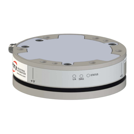
This part number used to be 9105-ECAT-Axia80. For calibration ranges, refer to Section 8.3—Calibration Ranges. Figure 2.2—Identifying Grooves (Axia80-M8 shown as a reference) Identifying Groove Pinnacle Park • 1031 Goodworth Drive • Apex, NC 27539 USA • Tel: +1.919.772.0115 • Fax: +1.919.772.8259 • www.ati-ia.com... -
Page 13: Installation
Manual, F/T Sensor, EtherCAT Axia Document #9610-05-EtherCAT Axia-09 3. Installation WARNING: Performing maintenance or repair on the sensor when circuits (e.g. power, water, and air) are energized could result in death or serious injury. Discharge and verify all energized circuits are de-energized in accordance with the customer’s safety practices and policies. CAUTION: Modification or disassembly of the sensor could cause damage and void the warranty. - Page 14 Manual, F/T Sensor, EtherCAT Axia Document #9610-05-EtherCAT Axia-09 If the customer chooses to design and build an interface plate, the consider the following points: • The interface plate should include bolt holes for mounting fasteners as well as dowel pin and a boss for accurate positioning to the robot or customer’s device.
-
Page 15: Routing The Cable
Manual, F/T Sensor, EtherCAT Axia Document #9610-05-EtherCAT Axia-09 3.2 Routing the Cable The routing and bending radius of the cable depends upon the customer application. Unlike motionless applications, where the cable is in a static condition, dynamic applications subject the cable to a repetitive motion. - Page 16 Manual, F/T Sensor, EtherCAT Axia Document #9610-05-EtherCAT Axia-09 CAUTION: Subjecting the connector to the repetitive motion will cause damage to the connector. Restrain the cable close to the connector so that the repetitive motion of the robot does not interfere with the cable connector. For added stability, zip ties can be used to secure the cable to a mounting bracket (refer to the following figure).
- Page 17 Manual, F/T Sensor, EtherCAT Axia Document #9610-05-EtherCAT Axia-09 CAUTION: Do not cable ties or zip ties to bundle cables or restrain the cable to the robot arm. Directly affixing cable ties or zip ties to the cable jacket will prevent power and signal communication between the F/T sensor and robot controller. Use hook and loop or Velcro straps on the cable jacket surfaces. Examples of the incorrect and correct methods to restrain or bundle cables are in the following pictures: CORRECT INCORRECT DO NOT USE...
-
Page 18: Installing The Sensor To The Robot
Using a 4 mm hex key, secure the sensor to the mounting adapter plate with the (6) M5 socket head cap screws, class 12.9. Tighten the fasteners per the specifications in the following table. Table 3.2—Torque Values for Axia Models Model Torque Axia80-M8 52 in-lbs (5.88 Nm) Axia80-M20 Axia80-M50 75 in-lbs (8.47 Nm) 4. -
Page 19: Removing The Sensor From The Robot
Manual, F/T Sensor, EtherCAT Axia Document #9610-05-EtherCAT Axia-09 Figure 3.5—Installation of the Sensor to the Robot Robot Dowel Pin Mounting Fasteners Interface Plate (9105-IP-2118 shown) Note: Cable lengths are shortened Mounting in the figure for reference only. Fasteners (2) Dowel Pin Mounting to the Robot or Interface Plate Power and... -
Page 20: Pin Assignment For The Ethercat And Power Connection
Manual, F/T Sensor, EtherCAT Axia Document #9610-05-EtherCAT Axia-09 3.5 Pin Assignment for the EtherCAT and Power Connection CAUTION: Ensure the cable shield is properly grounded. Improper shielding on the cables can cause communication errors and inoperative sensors. Pin assignments for the power and EtherCAT connection on the sensor and cables are in the following Specifications. -
Page 21: Pin Assignment For Cable P/N 9105-C-Zc28-U-Rj45S-X
Manual, F/T Sensor, EtherCAT Axia Document #9610-05-EtherCAT Axia-09 3.5.3 Pin Assignment for Cable P/N 9105-C-ZC28-U-RJ45S-X This cable has (2) branches: an unterminated end for power and a RJ45 connection for EtherCAT. For the signals and corresponding pin numbers/wire color, refer to the following sections. 3.5.3.1 Branch 1, Unterminated End for Power Connection The signals and corresponding wire jacket color for the unterminated wires which connect to the customer’s device are in the following table:... -
Page 22: Accuracy Check Procedure
Manual, F/T Sensor, EtherCAT Axia Document #9610-05-EtherCAT Axia-09 3.6 Accuracy Check Procedure Complete the following procedures after the initial installation of the sensor to the robot and once annually for maintenance. NOTICE: The mass on the tool side can be the weight of the tooling used in the application. 1. - Page 23 Manual, F/T Sensor, EtherCAT Axia Document #9610-05-EtherCAT Axia-09 6. The calculated tooling masses for all (6) points should deviate from each other by less than twice the worst accuracy rating of the sensor. • For example: the Axia80-M20 sensor’s rated accuracy is 2% the range on all axes. For a 500 N F range and a 900 N F range, the allowable errors of any single data point would be ±...
-
Page 24: Operation
Manual, F/T Sensor, EtherCAT Axia Document #9610-05-EtherCAT Axia-09 4. Operation Information required when using software to operate the EtherCAT Sensor is provided in the following sections. Knowledge of EtherCAT standards and operation is required to communicate with the EtherCAT sensor. 4.1 Sensor Environment CAUTION: Damage to the outer jacketing of the sensor cable could enable moisture or water to enter an otherwise sealed sensor. Ensure the cable jacketing is in good... -
Page 25: Sensor Status Led
Manual, F/T Sensor, EtherCAT Axia Document #9610-05-EtherCAT Axia-09 4.2.4 Sensor Status LED One LED signals the health status of the sensor as follows: LED State Description No power. Normal operation. Green The sensor’s electronics are functioning and communicating. Power-up self testing. Flashing green At power-up, the sensor completes diagnostic testing to verify internal electronics are functioning. -
Page 26: Low-Pass Filter
Manual, F/T Sensor, EtherCAT Axia Document #9610-05-EtherCAT Axia-09 4.4 Low-pass Filter The power-on default selection is no filtering. The “Filter Selection” field in Section 5.2.1.11—Object controls the current filter selection. The cutoff frequency (for example: -3 dB 0x7010: Control Codes frequency) is dependent on the sample rate selection which is defined in Section 4.3—Sample Rate. - Page 27 Manual, F/T Sensor, EtherCAT Axia Document #9610-05-EtherCAT Axia-09 Figure 4.1—Filter Attenuation at 0.5 kHz Sample Rate 0.0 dB 200 Hz 60 Hz -6.0 dB 22 Hz 10 Hz -12.0 dB 5 Hz Attenuation 2.5 Hz -18.0 dB 1.3 Hz 0.6 Hz 0.3 Hz -24.0 dB -30.0 dB...
- Page 28 Manual, F/T Sensor, EtherCAT Axia Document #9610-05-EtherCAT Axia-09 Figure 4.3—Filter Attenuation at 2 kHz Sample Rate 0.0 dB 500 Hz 235 Hz 90 Hz -6.0 dB 43 Hz 20 Hz -12.0 dB 10 Hz Attenuation 5 Hz 2.4 Hz -18.0 dB 1.4 Hz -24.0 dB -30.0 dB...
-
Page 29: Tool Transformation
Manual, F/T Sensor, EtherCAT Axia Document #9610-05-EtherCAT Axia-09 4.5 Tool Transformation By default, the forces and torques are reported with respect to a point of origin on the sensor that is set by ATI. For the sensor’s point of origin, refer to the customer drawing on the ATI website.. - Page 30 Manual, F/T Sensor, EtherCAT Axia Document #9610-05-EtherCAT Axia-09 After the displacements, the user point of origin rotates in the following order: 1. The first rotation is about the X-axis. • = +90° rotation. The user point of origin rotates +90° about the X-axis, in the Recall in this example R following figure.
-
Page 31: Avoid Overloading The Sensor During Tool Transformation
Manual, F/T Sensor, EtherCAT Axia Document #9610-05-EtherCAT Axia-09 A user can issue tool transformation commands through EtherCAT dictionary Object 0x2020 (refer to Section 5.2.1.2—Object 0x2020: Tool Transformation). 4.5.1 Avoid Overloading the Sensor During Tool Transformation It is possible for the user to set a reference point of origin that does not detect that a torque is applied to the customer tooling, and by extension, the sensor. -
Page 32: Ethercat Bus Interface
Manual, F/T Sensor, EtherCAT Axia Document #9610-05-EtherCAT Axia-09 5. EtherCAT Bus Interface The EtherCAT bus interface enables users to perform the following actions: • Read the active calibration information matrix, and serial number • Read the firmware revision • Read force/torque data •... -
Page 33: Ati Specific Area Objects
Manual, F/T Sensor, EtherCAT Axia Document #9610-05-EtherCAT Axia-09 5.2.1 ATI Specific Area Objects The structure of these Objects are defined by ATI. 5.2.1.1 Object 0x2019: Product Description CAUTION: Most users should not edit the fields in Object 0x2019. Changing these fields results in the ATI-provided EtherCAT Axia ESI/XML file not working. Therefore, this Object is not visible with the standard EtherCAT Axia ESI/XML file. To change these fields, contact for support ft_support@ati-ia.com This read/write Object allows a user to change this field in order to brand the sensor as part of their own system. -
Page 34: Object 0X2020: Tool Transformation
Manual, F/T Sensor, EtherCAT Axia Document #9610-05-EtherCAT Axia-09 5.2.1.2 Object 0x2020: Tool Transformation This Object allows the settings for the function tool transformation to be viewed or changed. After entering the changes, commit to the changes by entering “123” into the “Commit” field at the bottom of the Object. - Page 35 Manual, F/T Sensor, EtherCAT Axia Document #9610-05-EtherCAT Axia-09 Table 5.3— Object Index (hex) 0x2021: Calibration Subindex Name Type Description Value Unit 0x2f Force Units USINT Klbf Value Unit lbf-in lbf-ft 0x30 Torque Units USINT Kgf-cm 0x31 Max Fx Counts 0x32 Max Fy Counts 0x33 Max Fz Counts The maximum rated value for DINT...
-
Page 36: Object 0X2080: Diagnostic Readings
Manual, F/T Sensor, EtherCAT Axia Document #9610-05-EtherCAT Axia-09 5.2.1.4 Object 0x2080: Diagnostic Readings This read-only Object provides firmware version information. In this version Object, the following fields are available: Table 5.4— Object Index (hex) 0x2080: Diagnostic Readings Subindex Name Type Description The voltage of the external 0x01... -
Page 37: Object 0X2090: Version
Manual, F/T Sensor, EtherCAT Axia Document #9610-05-EtherCAT Axia-09 5.2.1.5 Object 0x2090: Version This read-only Object provides firmware version information. In this version Object, the following fields are available: Table 5.6— Object Index (hex) 0x2090: Version Subindex Name Type Description 0x01 Major Major Version UINT... -
Page 38: Object 0X6010: Status Code
Manual, F/T Sensor, EtherCAT Axia Document #9610-05-EtherCAT Axia-09 5.2.1.7 Object 0x6010: Status Code This Object contains a single DINT value (at subindex 0), with the following bitmap: Table 5.8— Object Index (hex) 0x6010: Status Code Indicates Description Number an Error? Internal Temperature Out of Range: This bit is active (high) if the temperature is outside the range -5 to 70°C. -
Page 39: Status Code: Force/Torque Out Of Range
Manual, F/T Sensor, EtherCAT Axia Document #9610-05-EtherCAT Axia-09 5.2.1.8 Status Code: Force/Torque Out of Range Bit 30 in is set when a F/T load is outside the sensor’s detection capability. Bit 30 is set Table 5.8 when either of the following conditions are TRUE: • The total percentage of the calibrated range used by F axes is greater than 105%. -
Page 40: Object 0X6020: Sample Counter
Manual, F/T Sensor, EtherCAT Axia Document #9610-05-EtherCAT Axia-09 The F equation simplifies as follows: Because the F equation simplified to TRUE, bit 30 in Table 5.8 is set. 5.2.1.9 Object 0x6020: Sample Counter This Object contains a single 32-bit unsigned integer at subindex 0 that increases by one each time a F/T sample (one complete set of gage data) is read. -
Page 41: Object 0X7010: Control Codes
Manual, F/T Sensor, EtherCAT Axia Document #9610-05-EtherCAT Axia-09 5.2.1.11 Object 0x7010: Control Codes This Object is mapped into the RxPDO for real-time control of the F/T system. This Object contains the following fields: Table 5.11— Object Index (hex) 0x7010: Control Codes Subindex Name Type Description... -
Page 42: Ethercat Communication Area Objects
Manual, F/T Sensor, EtherCAT Axia Document #9610-05-EtherCAT Axia-09 5.2.2 EtherCAT Communication Area Objects The structure of these 0x1000 Objects are defined by the EtherCAT ® Technology Group. ATI does not use all fields. 5.2.2.1 Object 0x1000: Device Type This read-only Object describes the type of EtheCAT device. Table 5.12—Object Index (hex) 0x1000: Device Type Default Default... -
Page 43: Object 0X1018: Identity
Manual, F/T Sensor, EtherCAT Axia Document #9610-05-EtherCAT Axia-09 5.2.2.3 Object 0x1018: Identity This read-only Object contains information about the connected EtherCAT device (in this case, the Technology Group defines the structure of this Object, ® ATI EtherCAT Axia sensor). The EtherCAT and ATI defines the values for each ATI product. -
Page 44: Unused Ethercat Objects
Manual, F/T Sensor, EtherCAT Axia Document #9610-05-EtherCAT Axia-09 5.2.2.4 Unused EtherCAT Objects Technology Group defines the structure of these Object but leaves them as ® The EtherCAT optional. Currently, ATI does not use these fields. Instead, the information is included in Section 5.2.1—ATI Specific Area Objects. -
Page 45: How To Interpret Hexadecimal Output
Manual, F/T Sensor, EtherCAT Axia Document #9610-05-EtherCAT Axia-09 5.2.3 How to Interpret Hexadecimal Output The user converts hexadecimal outputs to a 32-bit binary number that correlates to a code in a dictionary Object. An example of bit patterns are in the following table. Table 5.16—Bit Pattern Examples Simple Description Bit Number... -
Page 46: Establishing Communication With The Ethercat Axia Sensor
Manual, F/T Sensor, EtherCAT Axia Document #9610-05-EtherCAT Axia-09 5.3 Establishing Communication with the EtherCAT Axia Sensor The following steps guides the user through initializing communication between the EtherCAT Axia sensor and the customer’s EtherCAT master device. Always refer to the software manual for the EtherCAT master device for instructions best suited for your application. -
Page 47: Troubleshooting
Manual, F/T Sensor, EtherCAT Axia Document #9610-05-EtherCAT Axia-09 7. Troubleshooting This section includes answers to some issues that might arise when setting up and using the EtherCAT Axia. The question or concern is listed followed by its probable answer or solution. They are categorized for easy reference. The information in this section should answer many questions that might arise in the field. -
Page 48: Errors With Force And Torque Readings
Manual, F/T Sensor, EtherCAT Axia Document #9610-05-EtherCAT Axia-09 7.1 Errors with Force and Torque Readings Inaccurate data from the sensor’s strain gages can cause errors in force/torque readings. These errors can result in problems with sensor biasing and accuracy. Listed in the following table are the basic problems of inaccurate data. -
Page 49: Specifications
8.3 Calibration Ranges Table 8.3—Calibration Range 0 and Calibration Range 1 Model Axia80-M8 Axia80-M20 Axia80-M50 Txyz Txyz... -
Page 50: Terms And Conditions Of Sale
Manual, F/T Sensor, EtherCAT Axia Document #9610-05-EtherCAT Axia-09 9. Terms and Conditions of Sale The following Terms and Conditions are a supplement to and include a portion of ATI’s Standard Terms and Conditions, which are on file at ATI and available upon request. ATI warrants to Purchaser that force torque sensor products purchased hereunder will be free from defects in material and workmanship under normal use for a period of one (1) year from the date of shipment.
Need help?
Do you have a question about the Axia80-M8 and is the answer not in the manual?
Questions and answers