Table of Contents
Advertisement
Advertisement
Table of Contents

Related Manuals for ATI Technologies 9105-PS-1


Summary of Contents for ATI Technologies 9105-PS-1
- Page 1 F/T Sensor Data Acquisition (DAQ) Systems Manual Document #: 9620-05-DAQ.indd Engineered Products for Robotic Productivity Pinnacle Park • 1031 Goodworth Drive • Apex, NC 27539 • Tel: +1-919.772.0115 • Fax: +1-919.772.8259 • www.ati-ia.com • Email: info@ati-ia.com...
-
Page 2: Foreword
Manual, F/T Sensor, Data Acquisition (DAQ) Systems Document #9620-05-DAQ.indd-20 Foreword Information contained in this document is the property of ATI Industrial Automation, Inc. and shall not be reproduced in whole or in part without prior written approval of ATI Industrial Automation, Inc. The information herein is subject to change without notice and should not be construed as a commitment on the part of ATI Industrial Automation, Inc. -
Page 3: Table Of Contents
Manual, F/T Sensor, Data Acquisition (DAQ) Systems Document #9620-05-DAQ.indd-20 Table of Contents Foreword ............................2 Glossary ............................6 Safety ............................7 1.1 Explanation of Notifications ......................7 General Safety Guidelines ......................7 Safety Precautions ........................7 Product Overview ........................8 System with a TW Transducer, IFPS Box, and USB DAQ Device ..........8 System with a TIF Transducer, PS Box, and DAQ Card ............. - Page 4 Manual, F/T Sensor, Data Acquisition (DAQ) Systems Document #9620-05-DAQ.indd-20 3.4.2.1 Windows Demo (Visual Basic 6.0) ..............22 3.4.2.2 LabVIEW Sample ..................... 22 3.4.3 Designing Your DAQ F/T Application ................23 3.4.3.1 Device Drivers for Your DAQ Device and Target Operating System....23 3.4.3.2 ATI DAQ F/T Components or C Library ............
- Page 5 RoHS Compliance ........................65 Safety Standards ......................... 65 Drawings ..........................66 9105-PS-1 – DAQ Power Supply ....................66 9105-IFPS-1 – DAQ Interface Power Supply ................67 9105-IFPSMC Multiple IFPS Box ....................68 10. Terms and Conditions of Sale ....................69 Appendix A –...
-
Page 6: Glossary
Manual, F/T Sensor, Data Acquisition (DAQ) Systems Document #9620-05-DAQ.indd-20 Glossary Definition Term Accuracy See Measurement Uncertainty. ActiveX Component A reusable software component for the Windows applications. A computer file containing transducer calibration information. This file must match the transducer Calibration File serial number and is required for operation. -
Page 7: Safety
Manual, F/T Sensor, Data Acquisition (DAQ) Systems Document #9620-05-DAQ.indd-20 1. Safety The safety section describes general safety guidelines to be followed with this product, explanations of the notifications found in this manual, and safety precautions that apply to the product. More specific notifications are imbedded within the sections of the manual where they apply. -
Page 8: Product Overview
Manual, F/T Sensor, Data Acquisition (DAQ) Systems Document #9620-05-DAQ.indd-20 2. Product Overview The DAQ Force/Torque sensor system is a multi-axis force and torque sensor system that simultaneously measures forces (Fx, Fy, and Fz) and torques (Tx, Ty, and Tz). Components are available for Single TW Transducer DAQ Systems, TIF Transducer DAQ Systems, and Multiple TW Transducer DAQ Systems. -
Page 9: System With A Tif Transducer, Ps Box, And Daq Card
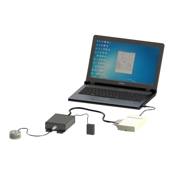
VHDCI 68-pin Connector (9105-C-PS-V68-X) Transducer DAQ Transducer Power (9105-TIF-THETA Shown) Supply (9105-PS-1) 12 Volt Wall Mount Power Supply, 2A, 24 W (9105-PS-KTPS24-12020MP) Pinnacle Park • 1031 Goodworth Drive • Apex, NC 27539 • Tel: 919.772.0115 • Fax: 919.772.8259 • • Email: www.ati-ia.com... -
Page 10: System With Multiple Transducers, Ifpsmc Box, And A Usb Daq Device
Manual, F/T Sensor, Data Acquisition (DAQ) Systems Document #9620-05-DAQ.indd-20 2.3 System with Multiple Transducers, IFPSMC Box, and a USB DAQ Device A Multiple Transducer system may consist of the following components: • Up to six TW Transducers • Multi-sensor Interface Box (Multiple IFPS) •... -
Page 11: System With Multiple Transducers, Ifpsmc Box, And A Daq Card
Manual, F/T Sensor, Data Acquisition (DAQ) Systems Document #9620-05-DAQ.indd-20 2.4 System with Multiple Transducers, IFPSMC Box, and a DAQ Card A Multiple Transducer system may consist of the following components: • Up to six TW Transducers • Multi-sensor Interface Box (Multiple IFPS) •... -
Page 12: System With Multiple Transducers, Ifpsmc Box, Wired I/O Connections For User Devices, And Usb Daq Device
Manual, F/T Sensor, Data Acquisition (DAQ) Systems Document #9620-05-DAQ.indd-20 2.5 System with Multiple Transducers, IFPSMC Box, Wired I/O Connections for User Devices, and USB DAQ Device A Multiple Transducer system may consist of the following components: • Up to six TW Transducers •... -
Page 13: Transducer
Manual, F/T Sensor, Data Acquisition (DAQ) Systems Document #9620-05-DAQ.indd-20 2.6 Transducer The transducer is a compact, durable, monolithic structure that converts force and torque into analog strain gage signals. The transducer is commonly used as a wrist sensor mounted between a robot and a robot end- effector. -
Page 14: Interface Power Supply Box
Manual, F/T Sensor, Data Acquisition (DAQ) Systems Document #9620-05-DAQ.indd-20 2.8 Interface Power Supply Box The Interface Power Supply (IFPS) box is used with the small Nano and Mini transducers. The IFPS Box supplies power to the transducer and supplementary electronics; it also conditions the transducer signals utilized by the data acquisition system. -
Page 15: Power Supply Box
PS box will use the 12 V source and the 5 V source will be ignored. Figure 2.9—Power Supply 20-pin Female Transducer Connector Power Supply Box (9105-PS-1) 26-pin Male DAQ Device Connector 12 V Wall Mount Power Supply, 2 A, 24 W (9105-PS-KTPS24-12020MP) 2.10 Power Supply Cable The power supply cable connects the Power Supply box or Interface Power Supply box to the DAQ Device or DAQ card. -
Page 16: Multiple Ifpsmc Boxes
Manual, F/T Sensor, Data Acquisition (DAQ) Systems Document #9620-05-DAQ.indd-20 2.11 Multiple IFPSMC Boxes Multiple-IFPSMC boxes allow for multiple transducers to be connected to one or two data acquisition cards. In cases where numerous transducers are utilized, a pair of data acquisition cards may be necessary. Figure 2.11—A Multiple 9105-IFPSMC Box 9105-C-PS-IFPSMC IFPSMC power supply... -
Page 17: Data Acquisition System
Manual, F/T Sensor, Data Acquisition (DAQ) Systems Document #9620-05-DAQ.indd-20 2.13 Data Acquisition System The Data Acquisition System converts transducer signals from analog voltages into data a computer can process. Using ATI software, transducer data is converted to force and torque values. The Data Acquisition System also supplies raw power to the transducer system. -
Page 18: System Functionality
Manual, F/T Sensor, Data Acquisition (DAQ) Systems Document #9620-05-DAQ.indd-20 3. System Functionality This section provides a functional outline of the F/T system. The F/T system is broken into four areas: Mechanical, Electrical, Load Calculations, and ATI DAQ Software. 3.1 Mechanical Description The transducer responds to applied forces and torque in accordance with Newton’s third law which states: For every action there is always an opposed or equal reaction;... -
Page 19: Electronic Hardware
Manual, F/T Sensor, Data Acquisition (DAQ) Systems Document #9620-05-DAQ.indd-20 3.2 Electronic Hardware The electronic hardware measures changes in resistance; the software described in Section 3.4—ATI DAQ Software, converts the changes to force and torque components. depict an example of the electronic hardware used in a DAQ system. The figures Figure 3.2 Figure 3.3 also illustrate how the transducer’s voltage signal, created as a response to applied forces and torques are... -
Page 20: Load Calculation
Manual, F/T Sensor, Data Acquisition (DAQ) Systems Document #9620-05-DAQ.indd-20 3.3 Load Calculation Calculations must be performed to derive the loads sensed at the transducer. The transducer reports the loads as composite values that require conversion to values corresponding to the six Cartesian axes. ATI supplies software to perform these calculations. -
Page 21: Offset Correction
Manual, F/T Sensor, Data Acquisition (DAQ) Systems Document #9620-05-DAQ.indd-20 3.3.2 Offset Correction Offset correction is a bias vector that zeros out the force and torque data compensating for the weight of tooling or variation in room temperature. For an example without offset correction the tooling weight will be seen as a force data on the transducer, using offset correction the force from the weight of the tool will be zeroed out. -
Page 22: Ati Daq Software
Manual, F/T Sensor, Data Acquisition (DAQ) Systems Document #9620-05-DAQ.indd-20 3.4 ATI DAQ Software The computer with the F/T system’s data acquisition card installed or data acquisition device attached, converts the strain gage data into useful force and torque values. The ATI DAQ software provides a user interface for viewing and editing (or providing controls) the data values. -
Page 23: Designing Your Daq F/T Application
Manual, F/T Sensor, Data Acquisition (DAQ) Systems Document #9620-05-DAQ.indd-20 3.4.3 Designing Your DAQ F/T Application Your DAQ F/T application must include at least two components: 3.4.3.1 Device Drivers for Your DAQ Device and Target Operating System National Instruments includes several sets of Windows device drivers with their data acquisition devices, including 32-bit DLLs, LabVIEW VIs, and ActiveX controls. -
Page 24: Installation
Manual, F/T Sensor, Data Acquisition (DAQ) Systems Document #9620-05-DAQ.indd-20 4. Installation Before installing the transducer on the robot, install the DAQ system components and install the software on the computer connected to the DAQ system. After testing the transducer and DAQ system to check its functionality, the Transducer can be installed on the robot. - Page 25 [3b] Insert Unterminated Cable Ends Into Appropriate Screw Terminal Location [2,3,4,6] DAQ PS or and Tighten Set Screw IFPS Box (9105-PS-1 Shown) [4] 12 Volt Wall Mount Power Supply, [6] Connect the Male Connector on the 2A, 24 W (9105-PS-KTPS24-12020MP)
- Page 26 [1] USB Cable [4] 12 Volt Wall Mount Power Supply, 2A,24 W (9105-PS-KTPS24-12020MP) [2,3,4,6] DAQ PS or IFPS Box (9105-PS-1 Shown) [3b] If 12 Volt Wall Mount Power Supply is Being Used, do not Connect the Red Wire to DGND or the...
- Page 27 Manual, F/T Sensor, Data Acquisition (DAQ) Systems Document #9620-05-DAQ.indd-20 Table 4.1—Unterminated Cable (9105-C-PS-U-x) for a NI 32 and 64 Pin Screw Terminal DAQ Device NI 32 or 64 NI 64 Pin # and Pin # and Screw Description Wire Colors Screw Terminal Description Wire Colors...
- Page 28 Manual, F/T Sensor, Data Acquisition (DAQ) Systems Document #9620-05-DAQ.indd-20 4. If equipped, plug 12 volt wall mount power supply into outlet and connect the power supply cable to the PS or IFPS box. 5. For larger TIF transducers, connect the female connector on the transducer cable to the transducer. Line up the groove on the connector to the key in the port by rotating the connector while lightly forcing the connector into the port.
-
Page 29: Installing A Daq System With Multiple Transducers, Ifpsmc Box, And Daq Device
Manual, F/T Sensor, Data Acquisition (DAQ) Systems Document #9620-05-DAQ.indd-20 4.2 Installing a DAQ System with Multiple Transducers, IFPSMC Box, and DAQ Device 1. Install the data acquisition system hardware (DAQ card, DAQ Device, power supply, and/or cabling) and its accompanying software following the instructions included with the hardware. Refer to Figure 4.6 Figure 4.7. - Page 30 Manual, F/T Sensor, Data Acquisition (DAQ) Systems Document #9620-05-DAQ.indd-20 Figure 4.7—Multiple TW Transducers, IFPSMC, and DAQ Card System Installation (2) DAQ Cables [2, 3b] Note: [#] indicates the step number (9105-C-SHC6868EPM-1) VHDCI Connector [3b] [1] PCI DAQ Card (9105-M1PCI6225) Desktop running DAQ Software [1,6] (9030-05-1001 Software) Multi-sensor Interface Box [2,4,5] (9105-IFPSMC-6 Shown)
- Page 31 Manual, F/T Sensor, Data Acquisition (DAQ) Systems Document #9620-05-DAQ.indd-20 Figure 4.8—Rear view of Multiple TW Transducers, IFPSMC, and DAQ Card System Installation [4] 9105-C-PS-IFPSMC Note: [#] indicates the step number IFPSMC Power Supply (Included with Multi-sensor Interface Box) [4] Power Supply Connector [2] Connector 1 to DAQ Card...
-
Page 32: Installing A Daq System With Multiple Transducers, Ifpsmc Box, Wired I/O Connections, And Usb Daq Device
Manual, F/T Sensor, Data Acquisition (DAQ) Systems Document #9620-05-DAQ.indd-20 4.3 Installing a DAQ System with Multiple Transducers, IFPSMC Box, Wired I/O Connections, and USB DAQ Device To ensure a seamless connection between the 9105-IFPSMC-X box and a DAQ Device with screw- terminals, the following connections need to be made to connect the transducer strain gage voltage outputs to the DAQ Device screw-terminals. - Page 33 Manual, F/T Sensor, Data Acquisition (DAQ) Systems Document #9620-05-DAQ.indd-20 NOTICE: The connections from the SCB-68s to the user’s DAQ device should be made over shielded twisted pair wiring for noise immunity and to ensure that the shield connections are properly made. We recommend using differential mode for better noise performance. Use the appropriate screw terminals and wires gages to pass the sensor signals correctly through.
-
Page 34: Install The F/T Demo Software
Manual, F/T Sensor, Data Acquisition (DAQ) Systems Document #9620-05-DAQ.indd-20 4.4 Install the F/T Demo Software If a CD is provided with the product, use the CD to install the F/T software. The installation program should start automatically. If no CD is available, the software can be downloaded from the ATI website at: http:// click DAQ F/T to download the files. - Page 35 Manual, F/T Sensor, Data Acquisition (DAQ) Systems Document #9620-05-DAQ.indd-20 6. Once the DAQ system is set up and functioning properly, the transducer can be installed. While monitoring strain gage voltages for saturation errors with the ATI Demo software, install the transducer on the robot or any selected device to prevent exceeding the transducer’s overload rating.
-
Page 36: Electrical Connection Information
Manual, F/T Sensor, Data Acquisition (DAQ) Systems Document #9620-05-DAQ.indd-20 4.5 Electrical Connection Information This section contains detailed information about the electrical connections of the various F/T system components. NOTICE: Information in this section is intended for advanced users. Users whose systems include an ATI-supplied DAQ card may skip this section. -
Page 37: Electrical Specifications
Manual, F/T Sensor, Data Acquisition (DAQ) Systems Document #9620-05-DAQ.indd-20 4.5.2 Electrical Specifications Table 4.3—PS and IFPS box with transducer attached Signal Minimum Typical Maximum Units +12V External Power Input Supply Voltage +5V Power Input Voltage 4.65 +5V Power Input Power +5V Power Input Current @ 4VDC ++5V Power Input Current @ 5VDC +5V Power Input Current @ 12VDC +5V Power Input Current @ 15VDC... -
Page 38: Transducer Signals
Manual, F/T Sensor, Data Acquisition (DAQ) Systems Document #9620-05-DAQ.indd-20 4.5.3 Transducer Signals Details on the connections for transducers with on-board electronics (9105-TIF part numbers). These transducers have a 20-pin connector. User connections to transducers without on-board electronics (9105-TWx part numbers) are not supported and therefore not covered in this document. A 9105-TIF transducer connector mates to a Hirose HR25-9TP-20S connector. -
Page 39: Ps And Ifps Signals
Manual, F/T Sensor, Data Acquisition (DAQ) Systems Document #9620-05-DAQ.indd-20 4.5.4 PS and IFPS Signals 4.5.4.1 PS 20-pin Circular Connector The PS 20-pin circular connector signals and pin numbering are the same as the 9105- TIF transducer signals listed in Section 4.5.3—Transducer Signals. -
Page 40: Daq Card Connections
Manual, F/T Sensor, Data Acquisition (DAQ) Systems Document #9620-05-DAQ.indd-20 4.5.5 DAQ Card Connections 4.5.5.1 Standard DAQ Card Connections The standard DAQ card configuration uses National Instruments 68-pin M series connectors. Advanced users can use the following table to better understand the system connections. -
Page 41: Custom Daq Card Connections
Manual, F/T Sensor, Data Acquisition (DAQ) Systems Document #9620-05-DAQ.indd-20 4.5.5.2 Custom DAQ Card Connections Advanced users may have purchased systems that use an unterminated power supply cable. The NI signal names listed in Table 4.8 may be used as a guide when connecting the unterminated cable to other National Instruments data acquisition equipment. - Page 42 Manual, F/T Sensor, Data Acquisition (DAQ) Systems Document #9620-05-DAQ.indd-20 Figure 4.15—Single-Ended Connections to a Data Acquisition System A connection from the DAQ F/T’s AGnd/AIGnd line to the data acquisition system’s analog input ground or analog ground is required in most cases. This line allows the return of the small amount of current used by the data acquisition system.
-
Page 43: Using Unused Daq Card Resources
Manual, F/T Sensor, Data Acquisition (DAQ) Systems Document #9620-05-DAQ.indd-20 4.5.5.3 Using Unused DAQ Card Resources Additional functions not used in the standard configuration are available on the ATI- supplied DAQ card; however, information on using these resources is outside the scope of this manual. - Page 44 Manual, F/T Sensor, Data Acquisition (DAQ) Systems Document #9620-05-DAQ.indd-20 Table 4.10—Signal Allocation for Transducer Connectors Transducer NI +Input NI -Input DAQ Card Connector # DAQ Card Connector # Signal Differential Connector Channel Channel / NI +Input Pin / NI -Input Pin Channel AI 4 AI 4...
-
Page 45: Installing 12 Pin Jumpers On The Backplane To Make Unused Transducer Signals Available To The User
Manual, F/T Sensor, Data Acquisition (DAQ) Systems Document #9620-05-DAQ.indd-20 4.5.6.1 Installing 12 Pin Jumpers on the Backplane to Make Unused Transducer Signals Available to the User Tools required: #2 Phillips head screw driver Parts required: 12 pin jumpers supplied with the IFPSMC Box (ATI part number1590-2225000-12) (Amphenol FCI part number 69145-212LF) NOTICE: The following steps must be performed at an anti-static workstation. - Page 46 Manual, F/T Sensor, Data Acquisition (DAQ) Systems Document #9620-05-DAQ.indd-20 6. Remove the back panel with the backplane board attached. 7. Remove the jumpers from the bag supplied with the IFPSMC box. Jumpers can be installed for all the DAQ boards that are not installed in the IFPSMC box. Refer to Figure 4.18.
- Page 47 Manual, F/T Sensor, Data Acquisition (DAQ) Systems Document #9620-05-DAQ.indd-20 Figure 4.19—Multiple IFPS Box Connector 0 and Connector 1 Table 4.11—IFPSMC Box Connector 0 User Signals Available IFPS Model Signal Number IFPSMC-1 IFPSMC-2 IFPSMC-3 IFPSMC-4 IFPSMC-5 IFPSMC-6 P2.6 Available Available Available Available Available Available...
- Page 48 Manual, F/T Sensor, Data Acquisition (DAQ) Systems Document #9620-05-DAQ.indd-20 Table 4.11—IFPSMC Box Connector 0 User Signals Available IFPS Model Signal Number IFPSMC-1 IFPSMC-2 IFPSMC-3 IFPSMC-4 IFPSMC-5 IFPSMC-6 D GND Available Available Available Available Available Available D GND Available Available Available Available Available Available...
- Page 49 Manual, F/T Sensor, Data Acquisition (DAQ) Systems Document #9620-05-DAQ.indd-20 Figure 4.20—Multiple IFPS Box Connector 0 and Connector 1 Table 4.12—IFPSMC Box Connector 1 User Signals Available IFPS Model Signal Number IFPSMC-1 IFPSMC-2 IFPSMC-3 IFPSMC-4 IFPSMC-5 IFPSMC-6 Al 71 Available(+) Available(+) Available(+) Available(+) TC6-SG5(+)
- Page 50 Manual, F/T Sensor, Data Acquisition (DAQ) Systems Document #9620-05-DAQ.indd-20 Table 4.12—IFPSMC Box Connector 1 User Signals Available IFPS Model Signal Number IFPSMC-1 IFPSMC-2 IFPSMC-3 IFPSMC-4 IFPSMC-5 IFPSMC-6 Al 79 Available(-) Available(-) Available(-) Available(-) TC6-SG5(-) TC6-SG5(-) Al 70 Available(+) Available(+) Available(+) Available(+) TC6-SG4(+) TC6-SG4(+)
-
Page 51: Installing Additional Ifps Cards In An Ifpsmc Box
Manual, F/T Sensor, Data Acquisition (DAQ) Systems Document #9620-05-DAQ.indd-20 4.5.6.2 Installing Additional IFPS Cards in an IFPSMC Box Current IFPSMC box models have all transducer connectors installed on the front panel; additional IFPS cards can be added to use with additional transducers. Tools required: #2 Phillips head screw driver Parts required: 9105-IFPSMC-PCB NOTICE: The following steps must be done at an anti-static workstation. - Page 52 Manual, F/T Sensor, Data Acquisition (DAQ) Systems Document #9620-05-DAQ.indd-20 5. Look into the front of the IFPSMC box to verify there are no jumpers installed for the IFPS card you are installing. Refer to Figure 4.22. If the corresponding 12 pin jumper is installed for the slot to be populated, it must be removed.
- Page 53 Manual, F/T Sensor, Data Acquisition (DAQ) Systems Document #9620-05-DAQ.indd-20 10. Carefully attach the back panel to the IFPSMC box. Note: be sure not to pinch any wire between the back panel and the box. Secure the back panel with the (4) M4 pan head screws.
- Page 54 Manual, F/T Sensor, Data Acquisition (DAQ) Systems Document #9620-05-DAQ.indd-20 Figure 4.24—IFPSMC Box FT Connector Labels Attach the New FT Label Supplied with the Kit 16. Locate the FT serial number label supplied with the kit and fix the label to the front panel, next to the connector of the recently installed IFPS card.
-
Page 55: Power
Manual, F/T Sensor, Data Acquisition (DAQ) Systems Document #9620-05-DAQ.indd-20 4.5.6.3 Power The small connector on the rear of the box is for power input. A Murr 7000-08481- 0000000 connector (female) may be used to mate with the power input connector. Figure 4.26—Power Input Connector Table 4.14—IFPSMC Power Input Connector Pin Assignments Description... -
Page 56: Operation
Manual, F/T Sensor, Data Acquisition (DAQ) Systems Document #9620-05-DAQ.indd-20 5. Operation 5.1 Writing DAQ F/T Application See the ATI DAQ FT help file for information on developing your own application. 5.2 Data Collection Rates Our DAQ F/T sensor systems are designed to be electrically compatible with most commercially-available, general-purpose and high-accuracy data acquisition hardware. -
Page 57: Environmental
Manual, F/T Sensor, Data Acquisition (DAQ) Systems Document #9620-05-DAQ.indd-20 5.5 Environmental The standard F/T system is designed to be used in standard laboratory or light-manufacturing conditions. Transducers with an IP60 designation are able to withstand dusty environments. Transducers with an IP65 designation are able to withstand dusty environments and wash down, and those with an IP68 designation are able to withstand dusty environments and freshwater immersion to a specified depth. -
Page 58: Maintenance
Manual, F/T Sensor, Data Acquisition (DAQ) Systems Document #9620-05-DAQ.indd-20 6. Maintenance 6.1 Periodic Inspection For most applications, part replacement during normal operation is unnecessary. With industrial-type applications that frequently move the system’s cabling, the cable jacket should be periodically checked for signs of wear. -
Page 59: Removing And Replacing The Ifps Card For Recalibration
Manual, F/T Sensor, Data Acquisition (DAQ) Systems Document #9620-05-DAQ.indd-20 6.3.1 Removing and Replacing the IFPS Card for Recalibration Tools required: #2 Phillips head screw driver Parts required: 9105-IFPSMC-PCB NOTICE: The following steps need to be done at an anti-static workstation. NOTICE: Make sure the transducers are re-connected to the same connector on the front panel when re-assembling the IFPSMC box. - Page 60 Manual, F/T Sensor, Data Acquisition (DAQ) Systems Document #9620-05-DAQ.indd-20 6. Carefully remove the transducer connector harness from the IFPS card by simultaneously prying up both ends of the connector using your fingernails. See the “Lift Here” call out in Figure 6.2.
- Page 61 Manual, F/T Sensor, Data Acquisition (DAQ) Systems Document #9620-05-DAQ.indd-20 Figure 6.3—IFPSMC Box FT Connector Labels Attach the New FT Label Supplied with the Kit 12. Remove the old FT serial number label from the front panel and fix the FT serial number label supplied with the kit to the front panel for the IFPS card just installed.
-
Page 62: Troubleshooting
Manual, F/T Sensor, Data Acquisition (DAQ) Systems Document #9620-05-DAQ.indd-20 7. Troubleshooting This section includes answers to issues that might arise during the set-up and use of the DAQ system. Each potential question or problem is listed followed by its probable answer or solution; all are categorized for easy reference. -
Page 63: Errors With Force And Torque Readings
Manual, F/T Sensor, Data Acquisition (DAQ) Systems Document #9620-05-DAQ.indd-20 7.1 Errors with Force and Torque Readings Bad data from the transducer’s strain gages can cause errors in force/torque readings. These errors can result in problems with threshold monitoring, sensor biasing and accuracy. Listed below are basic conditions of bad data. -
Page 64: Detecting Failures (Diagnostics)
Manual, F/T Sensor, Data Acquisition (DAQ) Systems Document #9620-05-DAQ.indd-20 7.2 Detecting Failures (Diagnostics) 7.2.1 Detecting Connection Issues The F/T system is designed to output voltages that are within the specified output voltage range (±5V or ±10V) as long as the transducer is not being overloaded and is connected to the PS or IFPS box. -
Page 65: Regulatory Information
Manual, F/T Sensor, Data Acquisition (DAQ) Systems Document #9620-05-DAQ.indd-20 8. Regulatory Information The regulator information applies to the ATI product covered in this manual. Product described from other manufacturers products are excluded. It is the users responsibility to verify product other than ATI product meet the regulatory requirements. -
Page 66: Drawings
Manual, F/T Sensor, Data Acquisition (DAQ) Systems Document #9620-05-DAQ.indd-20 9. Drawings 9.1 9105-PS-1 – DAQ Power Supply Pinnacle Park • 1031 Goodworth Drive • Apex, NC 27539 • Tel: 919.772.0115 • Fax: 919.772.8259 • • Email: www.ati-ia.com info@ati-ia.com... -
Page 67: 9105-Ifps-1 - Daq Interface Power Supply
Manual, F/T Sensor, Data Acquisition (DAQ) Systems Document #9620-05-DAQ.indd-20 9.2 9105-IFPS-1 – DAQ Interface Power Supply Pinnacle Park • 1031 Goodworth Drive • Apex, NC 27539 • Tel: 919.772.0115 • Fax: 919.772.8259 • • Email: www.ati-ia.com info@ati-ia.com... -
Page 68: 9105-Ifpsmc Multiple Ifps Box
Manual, F/T Sensor, Data Acquisition (DAQ) Systems Document #9620-05-DAQ.indd-20 9.3 9105-IFPSMC Multiple IFPS Box Pinnacle Park • 1031 Goodworth Drive • Apex, NC 27539 • Tel: 919.772.0115 • Fax: 919.772.8259 • • Email: www.ati-ia.com info@ati-ia.com... -
Page 69: Terms And Conditions Of Sale
Manual, F/T Sensor, Data Acquisition (DAQ) Systems Document #9620-05-DAQ.indd-20 10. Terms and Conditions of Sale The following Terms and Conditions are a supplement to and include a portion of ATI’s Standard Terms and Conditions, which are on file at ATI and available upon request. ATI warrants to Purchaser that force torque sensor products purchased hereunder will be free from defects in material and workmanship under normal use for a period of one year from the date of shipment. -
Page 70: Appendix A - Tool Transformation
Manual, F/T Sensor, Data Acquisition (DAQ) Systems Document #9620-05-DAQ.indd-20 Appendix A – Tool Transformation The tool transformation allows you to enter a series of tool transformations in order to measure the forces and torques acting at a point other than the origin of the sensor. If you specify both rotations and displacements within a particular tool transformation, displacements are performed first, in the order DX, DY, DZ, then rotations are performed, in the order RX, RY, RZ. - Page 71 Manual, F/T Sensor, Data Acquisition (DAQ) Systems Document #9620-05-DAQ.indd-20 Rotation allows the customer to rotate the axes while maintaining the frame origin. Figure A.2 shows the direction of rotation about the axis. Rotation is measured in radians. When a value is entered for RX, RY, or RZ the following will result: • RX value will rotate Y and Z about X in the direction shown (see Figure A.2).
Need help?
Do you have a question about the 9105-PS-1 and is the answer not in the manual?
Questions and answers