
Related Manuals for ATI Technologies Axia80-M8


Summary of Contents for ATI Technologies Axia80-M8
- Page 1 Ethernet Axia F/T Sensor Manual Document #: 9610-05-Ethernet Axia Engineered Products for Robotic Productivity Pinnacle Park • 1031 Goodworth Drive • Apex, NC 27539 • Tel: +1.919.772.0115 • Fax: +1.919.772.8259 • www.ati-ia.com...
-
Page 2: Foreword
Manual, F/T Sensor, Ethernet Axia Document #9610-05-Ethernet Axia-09 Foreword Information contained in this document is the property of ATI Industrial Automation, Inc. and shall not be reproduced in whole or in part without prior written approval of ATI Industrial Automation, Inc. The information herein is subject to change without notice and should not be construed as a commitment on the part of ATI Industrial Automation, Inc. - Page 3 Manual, F/T Sensor, Ethernet Axia Document #9610-05-Ethernet Axia-09 Note Please read the manual before calling customer service, and have the following information available: Serial number (e.g., FT01234) 2. Transducer model (e.g., Axia, etc.) Calibration (e.g., US-15-50, SI-65-6, etc.) 4. Accurate and complete description of the question or problem •...
-
Page 4: Statement Of Compliance
Manual, F/T Sensor, Ethernet Axia Document #9610-05-Ethernet Axia-09 Statement of Compliance Pinnacle Park • 1031 Goodworth Drive • Apex, NC 27539 • Tel:+1 919.772.0115 • Fax:+1 919.772.8259 • www.ati-ia.com... -
Page 5: Table Of Contents
Manual, F/T Sensor, Ethernet Axia Document #9610-05-Ethernet Axia-08 Table of Contents Foreword ............................2 Statement of Compliance ....................... 4 Glossary ............................9 Safety ............................11 1.1 Explanation of Notifications ....................... 11 General Safety Guidelines ......................12 Safety Precautions ........................12 Product Overview ........................13 Overview of Axia Models ...................... - Page 6 Manual, F/T Sensor, Ethernet Axia Document #9610-05-Ethernet Axia-08 Bias ............................... 31 Tool Transformation ........................31 4.7.1 Avoid Overloading the Sensor During Tool Transformation ..........33 4.7.2 Example of Tool Transformation Functionality Through Telnet ......... 33 4.7.3 Example of Tool Transformation Functionality Through CGI ..........34 4.7.4 Example of Tool Transformation Functionality Through TCP ...........
- Page 7 Manual, F/T Sensor, Ethernet Axia Document #9610-05-Ethernet Axia-08 Common Gateway Interface (CGI) ..................71 URL Syntax Construction: ........................71 9.1.1 Assigning a New Values to a Variable ................71 CGI Variable: Settings (setting.cgi) ................... 72 Thresholding CGI (moncon.cgi) ....................72 9.4 CGI Variable: Configurations (config.cgi) .................
- Page 8 Manual, F/T Sensor, Ethernet Axia Document #9610-05-Ethernet Axia-08 14.6 Reducing Noise ........................... 87 14.6.1 Mechanical Vibration ......................87 14.6.2 Electrical Interference ....................... 87 14.7 Detecting Sensitivity Changes ....................88 14.8 Improving Ethernet Throughput ....................88 14.8.1 Direct Connection between Axia Ethernet and Host ............88 14.8.2 Choice of Operating System ....................
-
Page 9: Glossary
Manual, F/T Sensor, Ethernet Axia Document #9610-05-Ethernet Axia-09 Glossary Definitions Term Active Configuration The configuration that the system is currently using. Analog-to-digital converter The factory-supplied data used by Ethernet Axia sensor so it can report accurate Calibration sensor readings. Calibrations apply to a specific loading range. Common Gateway Interface (CGI) is the method of using web URLs to communicate data and parameters back to a web device. Complex Loading Any force or torque load that is not purely in one axis. - Page 10 Manual, F/T Sensor, Ethernet Axia Document #9610-05-Ethernet Axia-09 Definitions Term Media Access Code Identifier (MAC ID) is a unique number that is user assigned to MAC ID each device on an Ethernet network. Also called Node Address. The surface of the sensor that attaches to a fixed surface like an interface Mounting Adapter Plate | MAP plate or robot arm. Not Applicable Non-Volatile Memory. Storage of information or device memory that can be retrieved even after the device goes through a power cycle.
-
Page 11: Safety
Manual, F/T Sensor, Ethernet Axia Document #9610-05-Ethernet Axia-09 1. Safety The safety section describes general safety guidelines to be followed with this product, explanations of the notifications found in this manual, and safety precautions that apply to the product. More specific notifications are imbedded within the sections of the manual where they apply. -
Page 12: General Safety Guidelines
Manual, F/T Sensor, Ethernet Axia Document #9610-05-Ethernet Axia-09 1.2 General Safety Guidelines The customer should verify that the sensor is rated for the maximum load and torque expected during operation. Because static forces are less than the dynamic forces from the acceleration or declaration of the robot, be aware of the dynamic loads caused by the robot. -
Page 13: Product Overview
Manual, F/T Sensor, Ethernet Axia Document #9610-05-Ethernet Axia-09 2. Product Overview The Ethernet Axia Force/Torque (F/T) sensor measures six components of force and torque (F ) and communicates this data to customer devices via Ethernet. The user can communicate with the sensor from a console through Telnet or CGI. -
Page 14: Overview Of Axia Models
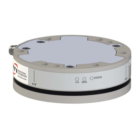
Formally 9105-NET-Axia80-ZC22 For calibration ranges, refer to Section 15.3—Calibration Ranges. Figure 2.2—Identifying Grooves (Axia80-M8 shown as a reference) Identifying Groove Pinnacle Park • 1031 Goodworth Drive • Apex, NC 27539 • Tel:+1 919.772.0115 • Fax:+1 919.772.8259 • www.ati-ia.com... -
Page 15: Installation
Manual, F/T Sensor, Ethernet Axia Document #9610-05-Ethernet Axia-09 3. Installation WARNING: Performing maintenance or repair on the sensor when circuits (for example: power, water, and air) are energized could result in death or serious injury. Discharge and verify all energized circuits are de-energized in accordance with the customer’s safety practices and policies. CAUTION: Using fasteners that exceed the customer interface depth penetrates the body of the sensor, damages the electronics, and voids the warranty. - Page 16 Manual, F/T Sensor, Ethernet Axia Document #9610-05-Ethernet Axia-09 If the customer chooses to design and build an interface plate, the consider the following points: • The interface plate should include bolt holes for mounting fasteners as well as dowel pin and a boss for accurate positioning to the robot or customer’s device.
-
Page 17: Routing The Cable
Manual, F/T Sensor, Ethernet Axia Document #9610-05-Ethernet Axia-09 3.2 Routing the Cable The routing and bending radius of the cable depends upon the customer application. Unlike motionless applications, where the cable is in a static condition, dynamic applications subject the cable to a repetitive motion. - Page 18 Manual, F/T Sensor, Ethernet Axia Document #9610-05-Ethernet Axia-09 CAUTION: Subjecting the connector to the repetitive motion will cause damage to the connector. Restrain the cable close to the connector so that the repetitive motion of the robot does not interfere with the cable connector. For added stability, zip ties can be used to secure the cable to a mounting bracket (refer to the following figure).
- Page 19 Manual, F/T Sensor, Ethernet Axia Document #9610-05-Ethernet Axia-09 CAUTION: Do not cable ties or zip ties to bundle cables or restrain the cable to the robot arm. Directly affixing cable ties or zip ties to the cable jacket will prevent power and signal communication between the F/T sensor and robot controller. Use hook and loop or Velcro straps on the cable jacket surfaces. Examples of the incorrect and correct methods to restrain or bundle cables are in the following pictures: CORRECT INCORRECT...
-
Page 20: Installing The Sensor To The Robot
Using a 4 mm hex key, secure the sensor to the mounting interface plate with (6) M5 socket head cap screws (class 12.9). Tighten the fasteners per the specifications in the following table. Table 3.2—Torque Values for Axia Models Model Torque Axia80-M8 52 in-lbs (5.88 Nm) Axia80-M20 75 in-lbs (8.47 Nm) Axia80-M50 4. -
Page 21: Removing The Sensor From The Robot
Manual, F/T Sensor, Ethernet Axia Document #9610-05-Ethernet Axia-09 6. Properly restrain and route the power and Ethernet cable; refer to Section 3.2—Routing the Cable. 7. After installation is complete, the sensor is ready for an accuracy check. (refer to Section 3.6—Accuracy Check Procedure) 8. -
Page 22: Pin Assignment For The Ethernet And Power Connection
Manual, F/T Sensor, Ethernet Axia Document #9610-05-Ethernet Axia-09 3.5 Pin Assignment for the Ethernet and Power Connection CAUTION: Ensure the cable shield is properly grounded. Improper shielding on the cables can cause communication errors and inoperative sensor. Pin assignment for the power and Ethernet connections on the sensor and cables are in the following sections. -
Page 23: Pin Assignment For Cable P/N 9105-C-Zc28-U-Rj45S-X
Manual, F/T Sensor, Ethernet Axia Document #9610-05-Ethernet Axia-09 3.5.3 Pin Assignment for Cable P/N 9105-C-ZC28-U-RJ45S-X This cable has (2) branches: an unterminated end for power and a RJ45 connection for Ethernet. For the signals and corresponding pin numbers/wire color, refer to the following sections. 3.5.3.1 Branch 1, Unterminated End for Power Connection The signals and corresponding wire jacket color for the unterminated wires which connect to the customer’s device are in the following table:... -
Page 24: Accuracy Check Procedure
Manual, F/T Sensor, Ethernet Axia Document #9610-05-Ethernet Axia-09 3.6 Accuracy Check Procedure Complete the following procedures after the initial installation of the sensor to the robot and once annually for maintenance. NOTICE: The mass on the tool side can be the weight of the tooling used in the application. 1. - Page 25 Manual, F/T Sensor, Ethernet Axia Document #9610-05-Ethernet Axia-09 6. The calculated tooling masses for all (6) points should deviate from each other by less than twice the worst accuracy rating of the sensor. • For example: the Axia80-M20 sensor’s rated accuracy is 2% the range on all axes. For a 500 N F range and a 900 N F range, the allowable errors of any single data point would be ±...
-
Page 26: Operation
Manual, F/T Sensor, Ethernet Axia Document #9610-05-Ethernet Axia-09 4. Operation Information required when using the software to operate the Axia Ethernet sensor is in the following sections. Communicating with the sensor requires knowledge of Ethernet standards and operation. Commands to operate and configure the sensor can be sent in the following ways: •... -
Page 27: Diag Led
Manual, F/T Sensor, Ethernet Axia Document #9610-05-Ethernet Axia-09 4.2.3 DIAG LED One LED signals the communication status of the Ethernet Axia sensor interface as follows: Table 4.3—DIAG LED LED State Description Indicates an error in the STATUS word except the following: 1. -
Page 28: Low-Pass Filter
Manual, F/T Sensor, Ethernet Axia Document #9610-05-Ethernet Axia-09 4.5 Low-Pass Filter The power-on default selection is no filtering. The “filTC” field in Section 8.4—Console “CAL” | “SET” controls the current filter selection. The cutoff frequency (i.e. -3 dB frequency) Command Fields and Values is dependent on the sample rate selection, which is defined in Section 4.3—Sample Rate. - Page 29 Manual, F/T Sensor, Ethernet Axia Document #9610-05-Ethernet Axia-09 Figure 4.2—Filter Attenuation at 1 kHz Sample Rate 0.0 dB 350Hz 115 Hz -6.0 dB 45 Hz 21 Hz -12.0 dB 10 Hz Attenuation 5 Hz -18.0 dB 3 Hz 1.2 Hz -24.0 dB 0.7 Hz -30.0 dB...
- Page 30 Manual, F/T Sensor, Ethernet Axia Document #9610-05-Ethernet Axia-09 Figure 4.4—Filter Attenuation at 4 kHz Sample Rate 0.0 dB 1000 Hz 460 Hz 180 Hz 84 Hz -6.0 dB 40 Hz 20 Hz -12.0 dB 10 Hz Attenuation 4.7 Hz 2.7 Hz -18.0 dB -24.0 dB -30.0 dB...
-
Page 31: Bias
Manual, F/T Sensor, Ethernet Axia Document #9610-05-Ethernet Axia-09 4.6 Bias Biasing is useful for eliminating the effects of gravity (tool weight) or other acting forces. When the bias function is used, the software collects data for the forces and torques that are currently acting on the sensor and use these readings as a reference for future readings. - Page 32 Manual, F/T Sensor, Ethernet Axia Document #9610-05-Ethernet Axia-09 After the displacements, the user point of origin rotates in the following order: 1. The first rotation is about the X-axis. • = +90° rotation. The user point of origin rotates +90° about the X-axis, in the Recall in this example R following figure.
-
Page 33: Avoid Overloading The Sensor During Tool Transformation
Manual, F/T Sensor, Ethernet Axia Document #9610-05-Ethernet Axia-09 A user can issue tool transformation commands through these interfaces: a console interface through Telnet/CGI or the ATI website. To understand how to enter Tool Transformation commands through the Configurations page on the ATI website, refer to Section 6.6—F/T Configurations Page (config.htm). For examples on how to enter tool transformation commands through Telnet or CGI, refer to the examples in the following sections. -
Page 34: Example Of Tool Transformation Functionality Through Cgi
Manual, F/T Sensor, Ethernet Axia Document #9610-05-Ethernet Axia-09 user: set ttry 180 response: set ttry 180 ttry was “0” now “180” user: set ttrz 0 response: set ttrz 0 ttrz not changed • Send the tool transformation “tt” command: user: set tt response: set tt... -
Page 35: Status Code
Manual, F/T Sensor, Ethernet Axia Document #9610-05-Ethernet Axia-09 4.8 Status Code The following table is a bitmap from bit number 0 to 31 for the current condition of the sensor. For help reading this table with hexadecimal codes, refer to Section 4.8.2—How to Interpret Hexadecimal Output for the Status Code. - Page 36 Manual, F/T Sensor, Ethernet Axia Document #9610-05-Ethernet Axia-09 • The total percentage of the calibrated range used by F axes is greater than 105%. Refer and T to the following F equation. Refer to Section 15.3—Calibration Ranges for the calibrated ranges that are used in the preceding equations.
-
Page 37: How To Interpret Hexadecimal Output For The Status Code
Manual, F/T Sensor, Ethernet Axia Document #9610-05-Ethernet Axia-09 4.8.2 How to Interpret Hexadecimal Output for the Status Code The user converts hexadecimals to a 32-bit binary number that correlates to a status code from Table 4.7. An example of bit patterns are in the following table. Table 4.9—Bit Pattern Examples Simple Description Bit Number... -
Page 38: Diagnostic Monitoring
Manual, F/T Sensor, Ethernet Axia Document #9610-05-Ethernet Axia-09 4.9 Diagnostic Monitoring During operation, the Ethernet Axia firmware monitors the hardware. When the user applies power to the sensor, the firmware waits (5) seconds before evaluating the supply voltage for errors. Status messages are in the following table. -
Page 39: Connecting Through Ethernet
Manual, F/T Sensor, Ethernet Axia Document #9610-05-Ethernet Axia-09 5. Connecting Through Ethernet Different methods for setting an IP address and how to configure a Windows 7/8/10 and Windows Vista operating ® ® system to connect the sensor to the ATI Ethernet Axia sensor webpages, are covered in the following sections. For a sensor to connect through Ethernet, the user must configure the IP address setting of the sensor. -
Page 40: Connecting To The Ati Webpages Using A Windows Computer
Manual, F/T Sensor, Ethernet Axia Document #9610-05-Ethernet Axia-09 5.2 Connecting To the ATI Webpages Using a Windows Computer To initially access the ATI Ethernet Axia F/T web pages, configure the sensor to work on the network by assigning an IP address and provide basic information about the network. For the initial connection, directly connect the computer to the sensor and disconnect from LAN. - Page 41 Manual, F/T Sensor, Ethernet Axia Document #9610-05-Ethernet Axia-09 Figure 5.1—Windows Vista and Windows 7/8/10 Networking Information 3. Record the values and settings shown in the properties window. Save these values so that the computer can be returned to its original configuration. 4.
- Page 42 Manual, F/T Sensor, Ethernet Axia Document #9610-05-Ethernet Axia-09 11. On the left side of the page is a menu bar with buttons that link to various Ethernet Axia webpages. Click on the Communications button. Figure 5.3—The Ethernet Axia F/T Sensor Communications Page 12.
-
Page 43: Finding The Ethernet Axia Sensor On A Network
Manual, F/T Sensor, Ethernet Axia Document #9610-05-Ethernet Axia-09 14. Open up a new web browser window. Type the sensor’s IP address into the browser’s address bar, and press Enter. • The Ethernet Axia Sensor’s Welcome page should display again. 15. Communicate with the sensor over the network, without reconfiguring the communications settings. 5.3 Finding the Ethernet Axia Sensor on a Network To find the IP address assigned by the DHCP server to an Ethernet Sensor, refer to the following procedure;... - Page 44 Manual, F/T Sensor, Ethernet Axia Document #9610-05-Ethernet Axia-09 Figure 5.5—Discovery Tool NOTICE: In addition to the ATI website, ATI provides this discovery tool in a directory that is sent to the user upon receipt of the sensor. To access the tool in the directory (9030-05-1026), open the folder “Utilities”, open the folder “ATI Discovery Tool”, and then install the file named “setup” . Pinnacle Park • 1031 Goodworth Drive • Apex, NC 27539 • Tel:+1 919.772.0115 • Fax:+1 919.772.8259 • www.ati-ia.com...
-
Page 45: Configuring The Sensor With The Ethernet Axia Web
Manual, F/T Sensor, Ethernet Axia Document #9610-05-Ethernet Axia-09 6. Configuring the Sensor with the Ethernet Axia Web Pages The ATI Ethernet Axia F/T sensor web pages provide full configuration options for the sensor. On the left side of the website, a menu bar has buttons that link the user to other pages for settings and sensor information. The web pages use simple HTML browser scripting and do not require plug-in technology. -
Page 46: Snapshot Page (Rundata.htm)
Manual, F/T Sensor, Ethernet Axia Document #9610-05-Ethernet Axia-09 6.2 Snapshot Page (rundata.htm) This page displays the current sensor loading conditions. The information on the Snapshot page is static and becomes current after a user loads or reloads the page. Figure 6.3—Snapshot Page Transducer Loading Snapshot (User Units): Force/Torque Data: These fields display the force and torque data scaled in the user units that the user selected on the Configurations page. -
Page 47: Demo Page (Demo.htm)
Manual, F/T Sensor, Ethernet Axia Document #9610-05-Ethernet Axia-09 6.3 Demo Page (demo.htm) From the Demo page, the user may download the Java ® Demo Application. Refer to Section 7—Java® Demo Application for more information. Figure 6.4—Demo Page 6.4 ADC Settings Page (setting.htm) On the ADC Settings page, the user can select the following: the active calibration, ADC sampling frequency, low-pass filter cutoff frequency, and software bias values. -
Page 48: Thresholding Page (Moncon.htm)
Manual, F/T Sensor, Ethernet Axia Document #9610-05-Ethernet Axia-09 The descriptions for the fields on the ADC Settings page, 6.5, are the following: Figure Active Calibration: A user may select one of two calibrations to be applied to the force and torque readings. - Page 49 Manual, F/T Sensor, Ethernet Axia Document #9610-05-Ethernet Axia-09 Figure 6.6—Thresholding Threshold Monitoring: The user can enable or disable threshold monitoring by clicking the radial button. Relay Behavior: The user can select if the output code is calculated by bitwise OR’ing (trigger if any condition is true) or bitwise AND’ing (trigger only if ALL conditions are true).
- Page 50 Manual, F/T Sensor, Ethernet Axia Document #9610-05-Ethernet Axia-09 Threshold Condition Elements: Statement number. On / Off: Selects which statements are to be included in the processing of threshold conditions. Selects the axis to be used in the comparison statement. Available axes are: Axis: Table 6.1—Thresholding Statement Axis Selections Menu Value...
-
Page 51: F/T Configurations Page (Config.htm)
Manual, F/T Sensor, Ethernet Axia Document #9610-05-Ethernet Axia-09 When this statement’s comparison is found true, this 8-bit value will be bitwise Output Code: OR’ed with the Output Code values of all other true statements to form the threshold output. Any set bits remain latched until the user issues a Resent Latch. If no statements are true the threshold output is zero. -
Page 52: Communication Page (Comm.htm)
Manual, F/T Sensor, Ethernet Axia Document #9610-05-Ethernet Axia-09 6.7 Communication Page (comm.htm) On the Communication page, the user may view and edit the system’s Ethernet networking options. Usually these settings are set once when the user first setup the system and do not need to be changed later A detailed overview of setting up Ethernet communications with the sensor is in Section 5—Connecting Through... -
Page 53: System Information Page (Manuf.htm)
Manual, F/T Sensor, Ethernet Axia Document #9610-05-Ethernet Axia-09 6.8 System Information Page (manuf.htm) The System Information page provides the user with a summary of the Ethernet Axia sensor’s current state. ATI refers to this page, when troubleshooting the sensor. For status codes, refer to Section 4.8—Status Code. -
Page 54: Java Demo Application
Manual, F/T Sensor, Ethernet Axia Document #9610-05-Ethernet Axia-09 ® 7. Java Demo Application The user can collect and view F/T data through the Java demo application on a personal computer. Install Java ® ® version 6.0 (runtime 1.6.0) or later on the computer (download Java ®... - Page 55 Manual, F/T Sensor, Ethernet Axia Document #9610-05-Ethernet Axia-09 • If the demo is unable to make contact with the Ethernet Axia sensor, the force and torque values will display zero and the Force units and other configuration-related items will each display a question mark.
-
Page 56: Data Display With The Demo
Manual, F/T Sensor, Ethernet Axia Document #9610-05-Ethernet Axia-09 Figure 7.5—Windows Vista Firewall Alert 7.2 Data Display with the Demo features a live display of the current F/T data, sequence numbers, and status The main screen in Figure 7.3 code. To understand how to interpret the status code, refer to Section 4.8—Status Code. - Page 57 Manual, F/T Sensor, Ethernet Axia Document #9610-05-Ethernet Axia-09 Figure 7.6—Java ® Demo Application while Collecting Data 5. To stop collecting data, click the Stop Collecting button (the Collect Streaming button changes to Stop Collecting, during collections). Pinnacle Park • 1031 Goodworth Drive • Apex, NC 27539 • Tel:+1 919.772.0115 • Fax:+1 919.772.8259 • www.ati-ia.com...
-
Page 58: Demo Csv File Format
Manual, F/T Sensor, Ethernet Axia Document #9610-05-Ethernet Axia-09 7.4 Demo CSV File Format Information stored in the CSV file is organized as follows : Figure 7.7—Sample Data Opened in Spreadsheet Start Time: the date and time when the data collection started. Row 1: RDT Sample Rate: the speed (in samples per second) at which data is sent to the host Row 2:... - Page 59 Manual, F/T Sensor, Ethernet Axia Document #9610-05-Ethernet Axia-09 Table 7.1—CSV File Column Headings Column: Status Name: Time (hex) Sequence Sequence Status (hex): a 32-bit system status code for this row. To understand how to interpret Column A: hexadecimal code and find the status code, refer to Section 4.8—Status Code.
-
Page 60: The Errors Field Display Of The Demo
Manual, F/T Sensor, Ethernet Axia Document #9610-05-Ethernet Axia-09 7.5 The Errors Field Display of the Demo On the bottom of the Java demo application main window, an Errors field tracks errors that have occurred ® for an example). For assistance with troubleshooting these and the times they occurred (see Figure 7.8 14.3. -
Page 61: Console Interface Through Telnet
Manual, F/T Sensor, Ethernet Axia Document #9610-05-Ethernet Axia-09 8. Console Interface Through Telnet The Ethernet Axia sensor has a console interface that is available to the user through Telnet. 8.1 Setting-Up Communications By using a console interface on the computer, the user can communicate with the sensor. Free Telnet console software, such as PuTTY, is available online. -
Page 62: Console Commands
Manual, F/T Sensor, Ethernet Axia Document #9610-05-Ethernet Axia-09 3. After a terminal window opens, the session prompts the user to enter a Login (or username) and Password. The Login is “ati”; the password is “ati7720115”. 4. Enter a console command from, press the (enter) key to send the command. NOTICE: Commands which are entered are not case sensitive. - Page 63 Manual, F/T Sensor, Ethernet Axia Document #9610-05-Ethernet Axia-09 Table 8.1—Commands Command Operand(s) Description The peak command reports the highest and lowest F/T values that occured for a run-time and for all-time, since the last Not Applicable peak reset command was issued. PEAK No operand reports the peaks in units.
-
Page 64: Secondary Commands For The Query "C" Or "S" Command
Manual, F/T Sensor, Ethernet Axia Document #9610-05-Ethernet Axia-09 Table 8.1—Commands Command Operand(s) Description The “view” command reports properties such as the F/T part number, units, calibration date, and calibration family (refer to Section 15.3—Calibration Ranges). VIEW If a user sends this command with no operand, all calibrations are reported. -
Page 65: Examples Of Secondary Commands (Specifiers)
Manual, F/T Sensor, Ethernet Axia Document #9610-05-Ethernet Axia-09 Table 8.2—Secondary “c” or “s” Commands Secondary Command Category Notes Specifier The user can choose to view force and torque data in the x, y, z axis. The output value can be displayed in F/T counts or engineering Axis. -
Page 66: Console "Cal" | "Set" Command Fields And Values
Manual, F/T Sensor, Ethernet Axia Document #9610-05-Ethernet Axia-09 2. C TXY is interpreted as: user: s txy response: 0.0009 Nm 0.0009 Nm The C is a command for reporting continuous lines of data. b. The T specifies printing torques whenever an x, y, z, or m is seen from now on (on this line). - Page 67 Manual, F/T Sensor, Ethernet Axia Document #9610-05-Ethernet Axia-09 Table 8.3—“CAL” | “SET” Fields and Values User Field Long Name Description Example Contents Type Read/ Write max0 Max F Counts max1 Max F Counts The maximum 32-bit max2 Max F Counts 214748647 rated value for this unsigned...
- Page 68 Manual, F/T Sensor, Ethernet Axia Document #9610-05-Ethernet Axia-09 Table 8.3—“CAL” | “SET” Fields and Values User Field Long Name Description Example Contents Type Read/ Write The ADC update rate in Hz. The ADC rate must be one of the following in units Read of Hz: 16-bit...
- Page 69 Manual, F/T Sensor, Ethernet Axia Document #9610-05-Ethernet Axia-09 Table 8.3—“CAL” | “SET” Fields and Values User Field Long Name Description Example Contents Type Read/ Write Tool transformation distance units: 0 = in ttdu 1 = ft 2 = mm 3 = cm 8-bit integer 4 = m Tool...
- Page 70 Manual, F/T Sensor, Ethernet Axia Document #9610-05-Ethernet Axia-09 Table 8.3—“CAL” | “SET” Fields and Values User Field Long Name Description Example Contents Type Read/ Write Global monitor conditions are enabled or mcEnabled disabled: 0 = disabled 1 = enabled Global monitor conditions are Read momentary or...
-
Page 71: Common Gateway Interface (Cgi)
Manual, F/T Sensor, Ethernet Axia Document #9610-05-Ethernet Axia-09 9. Common Gateway Interface (CGI) A user can configure the sensor over Ethernet by using standard CGI protocol and standard HTTP GET method which sends configuration variables and their values in the requested URL. External factors to the sensor determine the maximum length of these URLs. -
Page 72: Cgi Variable: Settings (Setting.cgi)
Manual, F/T Sensor, Ethernet Axia Document #9610-05-Ethernet Axia-09 9.2 CGI Variable: Settings (setting.cgi) A user can specify certain global settings such as ADC rate, low-pass filter selection, and bias (refer to Section 6.4—ADC Settings Page (setting.htm) for related information). Table 9.1—setting.cgi Variables Allowed Variable Name Description Example Values... -
Page 73: Cgi Variable: Configurations (Config.cgi)
Manual, F/T Sensor, Ethernet Axia Document #9610-05-Ethernet Axia-09 Table 9.3—moncon.cgi Threshold Conditions Variable Allowed Description Example Name Values mcen Integers: 0 or 1 Threshold statement n : enable = 1 or disable = 0 mce0=1 Selects the axis evaluated by threshold statement n. Value Description Menu Value... -
Page 74: Cgi Variable: Communications (Comm.cgi)
Manual, F/T Sensor, Ethernet Axia Document #9610-05-Ethernet Axia-09 Table 9.4—config.cgi Variables Allowed Variable Name Description Values with the units that are specified Sets the tool transformation distance D cfgtfx0 in the variable: cfgtdu. with the units that are specified Sets the tool transformation distance D cfgtfx1 in the variable: cfgtdu. with the units that are specified Sets the tool transformation distance D cfgtfx2 in the variable: cfgtdu. -
Page 75: Tcp Interface
Manual, F/T Sensor, Ethernet Axia Document #9610-05-Ethernet Axia-09 10. TCP Interface TCP interface allows a more advanced user to write their own software to interact with the sensor. This software or C#. For a command-line demo of C#, refer to the ™... -
Page 76: Read Calibration Info Command
Manual, F/T Sensor, Ethernet Axia Document #9610-05-Ethernet Axia-09 10.4 Read Calibration Info Command uint8 command; /* Must be READCALINFO (1). */ uint8 reserved[19]; /* Should be all 0s. */ 10.5 Read Calibration Info Response uint16 header; /* always 0x1234. */ uint8 forceUnits;... -
Page 77: Write Tool Transform Command
Manual, F/T Sensor, Ethernet Axia Document #9610-05-Ethernet Axia-09 10.6 Write Tool Transform Command uint8 command; /* Must be WRITETRANSFORM (2). */ uint8 transformDistUnits; /* Units of dx,dy,dz */ uint8 transformAngleUnits; /* Units of rx,ry,rz */ int16 transform[6]; /* dx, dy, dz, rx, ry, rz */ uint8 reserved[5];... -
Page 78: System Settings Xml
Manual, F/T Sensor, Ethernet Axia Document #9610-05-Ethernet Axia-09 11. System Settings XML Pages A user application can retrieve the sensor settings in XML format by using standard Ethernet HTTP requests. This enables programs to read system settings such as the Counts per Force value. The Java ®... - Page 79 Manual, F/T Sensor, Ethernet Axia Document #9610-05-Ethernet Axia-09 Table 11.2—XML Elements in netftapi2.xml XML Element Data Type Description Reference setmce USINT Threshold processing status USINT[16] Threshold statemens’ individual enabling USINT[16] Threshold statements’ selected axes moncon USINT[16] Threshold statements’ comparisons DINT[16] Threshold staements’...
-
Page 80: Calibration Information (Netftcalapi.xml)
Manual, F/T Sensor, Ethernet Axia Document #9610-05-Ethernet Axia-09 11.2 Calibration Information (netftcalapi.xml) The XML page netftcalapi.xml retrieves information about a specific calibration. Retrieved calibration information has not been modified by any of the Ethernet Axia configuration settings. A calibration index can be specified when requesting this calibration information. This is done by appending ?index=n to the request, where n is the index of the desired calibration. -
Page 81: Udp Interface Using Rdt
Manual, F/T Sensor, Ethernet Axia Document #9610-05-Ethernet Axia-09 12. UDP Interface Using RDT The Ethernet Axia can output data at up to 7912 Hz over Ethernet using UDP. This method of fast data collection is called Raw Data Transfer (RDT). RDT provides the following data in a packet: forces, torques, and status codes of the Ethernet Axia. -
Page 82: Rdt Request For Records Structure
Manual, F/T Sensor, Ethernet Axia Document #9610-05-Ethernet Axia-09 12.1.1 RDT Request For Records Structure All RDT requests have the following structure: Uint16 command_header = 0x1234; // Required Uint16 command; // Command to execute Uint32 sample_count; // Samples to output (0 = infinite) • Set the command field of the RDT request to a command from Table... -
Page 83: Calculating F/T Values For Rdt
Manual, F/T Sensor, Ethernet Axia Document #9610-05-Ethernet Axia-09 12.2 Calculating F/T Values for RDT To obtain the real force and torque values, divide each force output value by the Counts per Force, and divide each torque output value by the Counts per Torque factor. The Counts per Force and Counts per Torque factors can befrom netftapi2.xml page. -
Page 84: Maintenance
Manual, F/T Sensor, Ethernet Axia Document #9610-05-Ethernet Axia-09 13. Maintenance 13.1 Periodic Inspection With industrial-type applications that frequently move the system’s cabling, check the cable jacket for signs of wear. The Axia sensor is IP64 rated. Debris and dust should be kept from accumulating on or in the sensor. -
Page 85: Errors Powering Up
Manual, F/T Sensor, Ethernet Axia Document #9610-05-Ethernet Axia-09 14.1 Errors Powering Up Table 14.1—Powering Up Symptom Cause and Resolution Check the sensor cable connections. Status LED stays red after the 20 second Verify the sensor cable is not damaged. power up phase. There may be an internal error in the sensor. -
Page 86: Errors With The Java
Manual, F/T Sensor, Ethernet Axia Document #9610-05-Ethernet Axia-09 14.3 Errors with the Java Demo ® Table 14.3—Java ® Demo Symptom Cause and Resolution Demo displays zeros for force and torque values and displays Check IP address and restart demo. question marks for configuration data. -
Page 87: Errors With Force And Torque Readings
Manual, F/T Sensor, Ethernet Axia Document #9610-05-Ethernet Axia-09 14.5 Errors with Force and Torque Readings Incorrect data from the sensor’s strain gages can cause errors in force/torque readings. Listed in the following table are the basic conditions of incorrect data. Use this table to troubleshoot a problem. In most cases, problems can be better identified while looking at the raw strain gage data, displayed on the Snapshot Section 6.2—Snapshot Page (rundata.htm) page. -
Page 88: Detecting Sensitivity Changes
Manual, F/T Sensor, Ethernet Axia Document #9610-05-Ethernet Axia-09 14.7 Detecting Sensitivity Changes Sensitivity checking of the sensor can also be used to measure the Ethernet Axia sensor’s condition. Apply known loads to the sensor and verify the system output matches the known loads. For example, a sensor mounted to a robot arm may have an end-effector attached to it. -
Page 89: Avoid Logging The Host To A Company Network
15.3 Calibration Ranges Table 15.3—Calibration Range 0 and Calibration Range 1 Model Axia80-M8 Axia80-M20 Axia80-M50 Parameter Txyz... -
Page 90: Drawings
Manual, F/T Sensor, Ethernet Axia Document #9610-05-Ethernet Axia-09 16. Drawings 16.1 Axia80 Force/Torque Sensor 9230-05-1543 Pinnacle Park • 1031 Goodworth Drive • Apex, NC 27539 • Tel:+1 919.772.0115 • Fax:+1 919.772.8259 • www.ati-ia.com... - Page 91 Manual, F/T Sensor, Ethernet Axia Document #9610-05-Ethernet Axia-09 Pinnacle Park • 1031 Goodworth Drive • Apex, NC 27539 • Tel:+1 919.772.0115 • Fax:+1 919.772.8259 • www.ati-ia.com...
-
Page 92: Cable, Axia Sensor To 8-Pin M12, 3M, 9105-C-Zc22-Zc28-4
Manual, F/T Sensor, Ethernet Axia Document #9610-05-Ethernet Axia-09 16.2 Cable, Axia Sensor to 8-pin M12, 3m, 9105-C-ZC22-ZC28-4 Pinnacle Park • 1031 Goodworth Drive • Apex, NC 27539 • Tel:+1 919.772.0115 • Fax:+1 919.772.8259 • www.ati-ia.com... -
Page 93: Cable, 8-Pin M12 Split To Shielded Rj45 And Unterminated Power, Ground, Shield, 4 M
Manual, F/T Sensor, Ethernet Axia Document #9610-05-Ethernet Axia-09 16.3 Cable, 8-pin M12 Split to Shielded RJ45 and Unterminated power, ground, shield, 4 m, 9105-C-ZC28-U-RJ45S-4 Pinnacle Park • 1031 Goodworth Drive • Apex, NC 27539 • Tel:+1 919.772.0115 • Fax:+1 919.772.8259 • www.ati-ia.com... -
Page 94: Terms And Conditions Of Sale
Manual, F/T Sensor, Ethernet Axia Document #9610-05-Ethernet Axia-09 17. Terms and Conditions of Sale The following Terms and Conditions are a supplement to and include a portion of ATI’s Standard Terms and Conditions, which are on file at ATI and available upon request. ATI warrants to Purchaser that force torque sensor products purchased hereunder will be free from defects in material and workmanship under normal use for a period of one (1) year from the date of shipment.
Need help?
Do you have a question about the Axia80-M8 and is the answer not in the manual?
Questions and answers