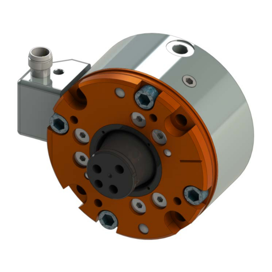
ATI Technologies SR‑61 Replacement Manual
Robotic collision sensor switch replacement manual
Hide thumbs
Also See for SR‑61:
- Manual (30 pages) ,
- Assembly, installation and operation manual (24 pages) ,
- Manual (35 pages)
Table of Contents
Advertisement
Quick Links
Advertisement
Table of Contents

Subscribe to Our Youtube Channel
Summary of Contents for ATI Technologies SR‑61
- Page 1 Robotic Collision Sensor SR‑61 Switch Replacement Manual U.S. Patent Nos. 6069415 and 6690208 Document #: 9610‑60‑1014 Engineered Products for Robotic Productivity Pinnacle Park • 1031 Goodworth Drive • Apex, NC 27539 USA • Tel: 919.772.0115 • Fax: 919.772.8259 • www.ati‑ia.com...
-
Page 2: Table Of Contents
Manual, Collision Sensor Switch Replacement,SR‑61 Document #9610‑60‑1014‑02 Table of Contents Safety ............................3 1.1 Explanation of Notifications ......................3 General Safety Guidelines ......................3 Safety Precautions ........................4 Electrical Connection ........................5 1.4.1 Test Switch Functionality ....................6 1.4.2 Replacement of Original Style Switch/Connector Block Assembly ........6 1.4.3 Replacement of Current Style Switch/Connector Block Assembly ........ -
Page 3: Safety
Manual, Collision Sensor Switch Replacement,SR‑61 Document #9610‑60‑1014‑02 1. Safety The safety section describes general safety guidelines to be followed with this product, explanation of the notifications found in this manual, and safety precautions that apply to the product. More specific notifications are imbedded within the sections of the manual where they apply. -
Page 4: Safety Precautions
Manual, Collision Sensor Switch Replacement,SR‑61 Document #9610‑60‑1014‑02 1.3 Safety Precautions WARNING: Do not perform maintenance or repair on the Collision Sensor with air pressure applied, current supplied to the sensor, or the robot not in a safe condition. Injury or equipment damage can occur if this is not observed. Always ensure that air pressure has been vented from the unit, that electrical current is not supplied to the Collision Sensor’s signal circuit, and that the robot is in a safe, locked‑out condition consistent with local and national safety standards before performing maintenance or... -
Page 5: Electrical Connection
Manual, Collision Sensor Switch Replacement,SR‑61 Document #9610‑60‑1014‑02 1.4 Electrical Connection The Collision Sensor is connected to the user’s control wiring as a normally‑open PNP or NPN proximity switch. The following sketch details the connections between the internal switch and the pins in the connector block assembly. -
Page 6: Test Switch Functionality
Manual, Collision Sensor Switch Replacement,SR‑61 Document #9610‑60‑1014‑02 1.4.1 Test Switch Functionality Once the Collision Sensor has been installed and connected as described in the preceding paragraphs, proper electrical operation of the unit may be confirmed. Supply the Collision Sensor with approximately 15 psi (1 bar) and ensure that the unit is 1.1. - Page 7 Manual, Collision Sensor Switch Replacement,SR‑61 Document #9610‑60‑1014‑02 Figure 1.3—Piston Location During Proximity Switch Installation 7. Screw the new proximity switch clockwise into the hole on the side of the body until it bottoms. 8. Rotate the connector block along with the proximity switch to prevent damage to the wires. 9.
-
Page 8: Replacement Of Current Style Switch/Connector Block Assembly
Manual, Collision Sensor Switch Replacement,SR‑61 Document #9610‑60‑1014‑02 1.4.3 Replacement of Current Style Switch/Connector Block Assembly 1. Remove the mounting screw using a 2.5 mm hex key (see Figure 1.4). 2. Pull the connector block away from the Collision Sensor. 3. Discard the entire assembly. Figure 1.4—Removal of Switch/Connector Block Assembly from the Collision Sensor 9160-SENSOR-061-2 M3 Socket Head Cap Screw... -
Page 9: Switch Adjustment
Manual, Collision Sensor Switch Replacement,SR‑61 Document #9610‑60‑1014‑02 1.5 Switch Adjustment There are (2) styles of switch/connector block assemblies for the SR‑61 Collision Sensor. The original style has a larger connector body than the current style. The current style has an adjustment set screw in the side of the connector body, refer to Figure 1.8. -
Page 10: Current Style Switch Adjustment
Manual, Collision Sensor Switch Replacement,SR‑61 Document #9610‑60‑1014‑02 11. Push on the press handle until the switch circuit opens and check the distance traveled on the dial indicator. 12. If the distance traveled is greater than desired turn the proximity switch counterclockwise. If the distance traveled is less turn the proximity switch clockwise. - Page 11 Manual, Collision Sensor Switch Replacement,SR‑61 Document #9610‑60‑1014‑02 3. Remove the user‑installed mounting hardware from the Collision Sensor and remove the unit. Take the unit to a test bench equipped with a clean working surface and compressed air. 4. Ensure that the Collision Sensor returns to its reset or working position with the stem fully extended and the alignment mark on the stem in line with the alignment mark on the cover plate (Temporarily supply approximately 60 psi (4 bars) to the unit.


Need help?
Do you have a question about the SR‑61 and is the answer not in the manual?
Questions and answers