Table of Contents
Advertisement
Quick Links
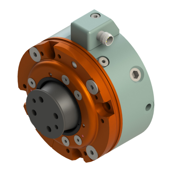
Robotic Collision Sensor
SR‑81 and SR‑101
Switch Replacement and Adjustment
Manual
U.S. Patent Nos. 6069415 and 6690208
Document #: 9610‑60‑1010
Engineered Products for Robotic Productivity
Pinnacle Park • 1031 Goodworth Drive • Apex, NC 27539 • Tel: +1‑919.772.0115 • Fax: +1‑919.772.8259 • www.ati‑ia.com
Advertisement
Table of Contents

Related Manuals for ATI Technologies SR‑81


Summary of Contents for ATI Technologies SR‑81
- Page 1 Robotic Collision Sensor SR‑81 and SR‑101 Switch Replacement and Adjustment Manual U.S. Patent Nos. 6069415 and 6690208 Document #: 9610‑60‑1010 Engineered Products for Robotic Productivity Pinnacle Park • 1031 Goodworth Drive • Apex, NC 27539 • Tel: +1‑919.772.0115 • Fax: +1‑919.772.8259 • www.ati‑ia.com...
-
Page 2: Foreword
Manual, Collision Sensor Switch Replacement, SR‑81/SR‑101 Document #9610‑60‑1010‑03 Foreword Please contact ATI Industrial Automation with any questions concerning your particular model. CAUTION: This manual describes the function, application and safety considerations of this product. This manual must be read and understood before any attempt is made to install or operate the product. -
Page 3: Table Of Contents
Manual, Collision Sensor Switch Replacement, SR‑81/SR‑101 Document #9610‑60‑1010‑03 Table of Contents Foreword ............................2 Glossary ............................4 Safety ............................5 1.1 Explanation of Notifications ......................5 General Safety Guidelines ......................5 Safety Precautions ........................6 Switch Replacement ........................ 7 Switch Adjustment ........................14 Drawings .......................... -
Page 4: Glossary
Manual, Collision Sensor Switch Replacement, SR‑81/SR‑101 Document #9610‑60‑1010‑03 Glossary Definition Term 8 mm Connector 8 mm electrical connector mounted in block attached to the side of the body. Cylindrical aluminum housing and air pressure chamber. An interface plate to Body the user’s robot is usually attached here. -
Page 5: Safety
Manual, Collision Sensor Switch Replacement, SR‑81/SR‑101 Document #9610‑60‑1010‑03 1. Safety The safety section describes general safety guidelines to be followed with this product, explanation of the notifications found in this manual, and safety precautions that apply to the product. More specific notifications are imbedded within the sections of the manual were they apply. -
Page 6: Safety Precautions
Manual, Collision Sensor Switch Replacement, SR‑81/SR‑101 Document #9610‑60‑1010‑03 1.3 Safety Precautions WARNING: Do not perform maintenance or repair on the Collision Sensor with air pressure applied, current supplied to the sensor, or the robot not in a safe condition. Injury or equipment damage can occur if this is not observed. Always ensure that air pressure has been vented from the unit, that electrical current is not supplied to the Collision Sensor’s signal circuit, and that the robot is in a safe, locked‑out condition consistent with local and national safety standards before performing maintance or... -
Page 7: Switch Replacement
Manual, Collision Sensor Switch Replacement, SR‑81/SR‑101 Document #9610‑60‑1010‑03 2. Switch Replacement Parts required: ATI Tool (3810-60-1489), Switch kit (9160-SWITCHKIT-081 for the SR-81 or 9160-SWITCHKIT-101 for the SR-101) Tools required: Allen wrenches (hex keys), Wire cutters, ATI Tool (3810-60-1489) Supplies required: Loctite 222 1. - Page 8 Manual, Collision Sensor Switch Replacement, SR‑81/SR‑101 Document #9610‑60‑1010‑03 8. Remove the (4) screws that secure the cover plate assembly to the body. CAUTION: Do not attempt to pry or wedge the cover plate assembly and body apart. Doing so can damage the mating surfaces and may render the parts unusable. Figure 2.3—Removing the Cover Plate 9.
- Page 9 Manual, Collision Sensor Switch Replacement, SR‑81/SR‑101 Document #9610‑60‑1010‑03 10. Remove actuator spring housing, actuation spring, actuation pin, switch carrier spring, and switch assembly. Discard parts. Figure 2.5—Removing the Switch 11. Insert the wires of the new switch assembly through the body post. Slide the switch assembly into position.
- Page 10 Manual, Collision Sensor Switch Replacement, SR‑81/SR‑101 Document #9610‑60‑1010‑03 12. Untwist the wires and feed them through the slot leading to the cavity on the side of the body. Ensure that the wires will lie side‑by‑side in the channel once the assembly has been completed. To prevent damage to the wires, temporarily apply masking tape to the channel once the wires are correctly positioned.
- Page 11 Manual, Collision Sensor Switch Replacement, SR‑81/SR‑101 Document #9610‑60‑1010‑03 14. Place the switch carrier spring into the body post on top of the switch assembly. Figure 2.9—Installing the Switch Carrier Spring Place the Switch Carrier Spring into the Body Post. 15. Place the spring into the actuation pin and then slide actuation pin into actuation pin housing. Figure 2.10—Inserting the Wire Connectors Place Actuation Pin Place Spring...
- Page 12 Manual, Collision Sensor Switch Replacement, SR‑81/SR‑101 Document #9610‑60‑1010‑03 17. Plug the micro header socket into the pcb header in the connector block. Figure 2.12—Connecting the Connector Block 18. Place the nylon washer on M3. Apply Loctite 222 to the connector block’s M3 mounting screw and thread it into the body and torque to 64 in‑ozs (0.45 Nm).
- Page 13 Manual, Collision Sensor Switch Replacement, SR‑81/SR‑101 Document #9610‑60‑1010‑03 20. If the unit was equipped with a C1 or C5 style IP‑65 sealing boot apply Loctite 548 Gasket Eliminator to the underside of the cover. Figure 2.14—Applying Gasket Eliminator 21. With the stem assembly upright, set the cover plate assembly onto it. Make certain that the alignment grooves are properly aligned.
-
Page 14: Switch Adjustment
Manual, Collision Sensor Switch Replacement, SR‑81/SR‑101 Document #9610‑60‑1010‑03 2.1 Switch Adjustment Tools required: Allen wrenches (hex keys), Arbor press, Dial idicator 1. Provide 20 psi to the air supply port (not required if equipped with preload springs) and insure that the Collision Sensor returns to its reset or working position with the stem fully extended and the alignment mark on the stem in line with the alignment mark on the cover plate. - Page 15 Manual, Collision Sensor Switch Replacement, SR‑81/SR‑101 Document #9610‑60‑1010‑03 Figure 2.17—Checking the Switch Height Adjustment Arbor Press Press Ram Dial Indicator Interface Plate Allen Wrench 5. Set a dial indicator in contact with the interface plate and adjust it so that the probe is vertical. Set the dial indicator height so that it can read at least 0.10”...
- Page 16 Manual, Collision Sensor Switch Replacement, SR‑81/SR‑101 Document #9610‑60‑1010‑03 7. If the distance traveled before the switch turns off is greater than desired, turn the adjusting screw clockwise. If the distance traveled is less, turn the adjusting screw counterclockwise (use a 1.5 mm hex key).
- Page 17 Manual, Collision Sensor Switch Replacement, SR‑81/SR‑101 Document #9610‑60‑1010‑03 11. Remove the masking tape covering the wire channel. Peel the paper backing off of the wire channel gasket and apply the gasket to the shallow recess straddling the wire channel. Be sure that the wires are laying side‑by‑side in the channel before smoothing the gasket into place.
-
Page 18: Drawings
Manual, Collision Sensor Switch Replacement, SR‑81/SR‑101 Document #9610‑60‑1010‑03 3. Drawings 3.1 SR‑81 Pinnacle Park • 1031 Goodworth Drive • Apex, NC 27539 • Tel: 919.772.0115 • Fax: 919.772.8259 • www.ati‑ia.com... - Page 19 Manual, Collision Sensor Switch Replacement, SR‑81/SR‑101 Document #9610‑60‑1010‑03 Pinnacle Park • 1031 Goodworth Drive • Apex, NC 27539 • Tel: 919.772.0115 • Fax: 919.772.8259 • www.ati‑ia.com...
- Page 20 Manual, Collision Sensor Switch Replacement, SR‑81/SR‑101 Document #9610‑60‑1010‑03 3.2 SR‑101 Pinnacle Park • 1031 Goodworth Drive • Apex, NC 27539 • Tel: 919.772.0115 • Fax: 919.772.8259 • www.ati‑ia.com...
- Page 21 Manual, Collision Sensor Switch Replacement, SR‑81/SR‑101 Document #9610‑60‑1010‑03 Pinnacle Park • 1031 Goodworth Drive • Apex, NC 27539 • Tel: 919.772.0115 • Fax: 919.772.8259 • www.ati‑ia.com...
-
Page 22: Terms And Conditions Of Sale
Manual, Collision Sensor Switch Replacement, SR‑81/SR‑101 Document #9610‑60‑1010‑03 4. Terms and Conditions of Sale The following Terms and Conditions are a supplement to and include a portion of ATI’s Standard Terms and Conditions, which are on file at ATI and available upon request. ATI warrants to Purchaser that Collision Sensor products purchased hereunder will be free from defects in material and workmanship under normal use for a period of one (1) year from the date of shipment.
Need help?
Do you have a question about the SR‑81 and is the answer not in the manual?
Questions and answers