ATI Technologies Q46 Manual
Turbidity measurement system
Hide thumbs
Also See for Q46:
- O & m manual (63 pages) ,
- Communications manual (23 pages) ,
- Profibus communication manual (21 pages)
Table of Contents
Advertisement
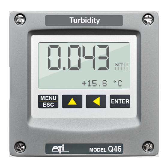
Model Q46/76
Turbidity Measurement
Home Office
Analytical Technology, Inc.
6 Iron Bridge Drive
Collegeville, PA 19426
Tel: 800-959-0299
610-917-0991
Fax: 610-917-0992
Email: sales@analyticaltechnology.com Email:sales@atiuk.com
System
European Office
ATI (UK) Limited
Unit 1 & 2 Gatehead Business Park
Delph New Road, Delph
Saddleworth OL3 5DE
Tel: +44 (0)1457-873-318
Fax: + 44 (0)1457-
874-468
Advertisement
Table of Contents

Related Manuals for ATI Technologies Q46


Summary of Contents for ATI Technologies Q46
- Page 1 Model Q46/76 Turbidity Measurement System Home Office European Office Analytical Technology, Inc. ATI (UK) Limited 6 Iron Bridge Drive Unit 1 & 2 Gatehead Business Park Collegeville, PA 19426 Delph New Road, Delph Saddleworth OL3 5DE Tel: 800-959-0299 Tel: +44 (0)1457-873-318...
- Page 2 PRODUCT WARRANTY Analytical Technology, Inc. (Manufacturer) warrants to the Customer that if any part(s) of the Manufacturer's equipment proves to be defective in materials or workmanship within the earlier of 18 months of the date of shipment or 12 months of the date of start- up, such defective parts will be repaired or replaced free of charge.
-
Page 3: Table Of Contents
5.23 Calibration Menu [CAL] ..35 Standard System ...... 5 5.24 Configuration Menu [CONFIG]36 Features ........6 5.25 Control Menu [CONTROL] .. 39 Q46/76 System Specifications .. 7 5.26 Diagnostics Menu [DIAG] ... 44 Q46/76 Performance PART 6 – CALIBRATION ....49 Specifications ........8 Turbidity Calibration .... - Page 4 Table of Figures 1 – Q46 E ................9 IGURE NCLOSURE IMENSIONS 2 - W ............... 10 IGURE ALL OR IPE MOUNT BRACKET 3 - W ................11 IGURE OUNTING IAGRAM 4 - P ................11 IGURE OUNTING IAGRAM 5 - P ..................
-
Page 5: Part 1 - Introduction
Part 1 - Introduction General The Model Q46/76 is a versatile on-line monitoring system designed for the continuous measurement of turbidity in water. It is intended for continuous monitoring of potable water filter outlets, raw water inlets, or turbidity monitoring of wastewater effluent. -
Page 6: Features
Q46/76 Turbidity Monitor Part 1 - Introduction Features · Standard Q46D electronic transmitters are designed to be a fully isolated instruments for operation from either 90-260 VAC or 12-24 VDC power supplies. · Two 4-20 mA analog outputs are standard, and a third analog output is available as an option. -
Page 7: Q46/76 System Specifications
Q46/76 Turbidity Monitor Part 1 - Introduction Q46/76 System Specifications Displayed Parameters Main input, 0.001 to 400 NTU Sensor temperature, -10.0 to 50.0°C (23 to 122ºF) Loop current, 4.00 to 20.00 mA Sensor slope/offset Model number and software version PID Controller Status... -
Page 8: Q46/76 Performance Specifications
Q46/76 Turbidity Monitor Part 1 - Introduction Ambient Temperature Analyzer Service, -20 to 60 °C (-4 to 140 ºF) Sensor Service, 0 to 55°C (23 to 131 °F) Storage, -30 to 70 °C (-22 to 158 ºF) Ambient Humidity 0 to 95%, indoor/outdoor use, non-condensing to rated... -
Page 9: Part 2 - Analyzer Mounting
Part 2 – Analyzer Mounting General All Q46 Series instruments offer maximum mounting flexibility. A bracket is included with each unit that allows mounting to walls or pipes. Choose a location that is readily accessible for calibrations and keep in mind that it will be necessary to use solutions during the calibration process. -
Page 10: Wall Or Pipe Mount
Q46/76 Turbidity Monitor Part 2 – Analyzer Mounting Wall or Pipe Mount A PVC mounting bracket with attachment screws is supplied with each transmitter (see Figure 2 for dimensions). The multi-purpose bracket is attached to the rear of the enclosure using the four flat head screws. The instrument is then attached to the wall using the four outer mounting holes in the bracket. -
Page 11: Figure 3 - Wall Mounting Diagram
Q46/76 Turbidity Monitor Part 2 – Analyzer Mounting Figure 3 - Wall Mounting Diagram MENU ENTER Figure 4 - Pipe Mounting Diagram O&M Manual Rev-J (8/17) -
Page 12: Panel Mount, Ac Powered Monitor
Q46/76 Turbidity Monitor Part 2 – Analyzer Mounting Panel Mount, AC Powered Monitor Panel mounting of an AC powered monitor uses the panel mounting flange molded into the rear section of the enclosure. Figure 5 - Panel Mount Diagram Figure 5 provides dimensions for the panel cutout required for mounting. The panel mounting bracket kit must be ordered separately (part number 05-0068). -
Page 13: Part 3 - Sensor Installation
Part 3 – Sensor Installation General The majority of turbidity applications require the use of a flowcell assembly. This method is best when monitoring very low turbidity values, such as filter effluent. The flowcell used with ATI’s turbidity system is designed to eliminate ambient light effects, and to allow sample pressure to be maintained through the flowcell minimizing air bubble formation that can cause measurement errors. -
Page 14: Figure 7 - Flowcell Clamp Diagram
Q46/76 Turbidity Monitor Part 3 – Sensor Installation Figure 7 - Flowcell Clamp Diagram Figure 8 below provides a detail of how the turbidity sensor is installed in the flowcell assembly. During installation of the sensor, be sure that the O-ring is seated properly in the groove at the end of the flowcell assembly. -
Page 15: Figure 9 - Inlet Tubing Arrangement
Q46/76 Turbidity Monitor Part 3 – Sensor Installation Figure 9 below shows the recommended installation tubing arrangement for the turbidity system. A 3-way valve is supplied to facilitate calibration of the turbidity monitor. Install the valve as shown below so that turbidity standards can easily be introduced into the flowcell. -
Page 16: In-Line Installation
Q46/76 Turbidity Monitor Part 3 – Sensor Installation Raw Water Flowcell Turbidity monitoring of raw water with potentially high turbidity levels cannot be done using the standard flowcell. For this kind of application, you need a flow chamber that does not contain very small restrictions like the flow control valve on the top of the standard flowcell. - Page 17 Q46/76 Turbidity Monitor Part 3 – Sensor Installation In-Line Installation Turbidity sensors may be installed directly into a flowing pipe system provided that the water does not contain a lot of entrained air. A 1 ½” flow tee assembly is available for this purpose.
-
Page 18: Figure 12 - Flow Tee Exploded View
Q46/76 Turbidity Monitor Part 3 – Sensor Installation Figure 12 - Flow Tee Exploded View O&M Manual Rev-J (8/17) -
Page 19: Submersible Installation
Q46/76 Turbidity Monitor Part 3 – Sensor Installation Submersible Installation The standard turbidity sensor may also be used for submersion installations. Note that turbidity sensors may be affected by bright ambient light conditions. If submerged sensors are to be used outdoors, always use the Auto-Clean version of the sensor as it contains a light shield to minimize these effects. -
Page 20: Part 4 - Electrical Installation
Part 4 – Electrical Installation General The Q46 is powered in one of two ways, depending on the version purchased. The 12-24 VDC powered analyzer requires a customer supplied DC power supply. The 90-260 VAC version requires line power. Please verify the type of unit before connecting any power. - Page 21 Q46/76 Turbidity Monitor Part 4 – Electrical Installation There is no standard ground resistance universally recognized. Many agencies recommend a ground resistance value of 5 ohms or less. The NEC recommends an impedance to ground of less than 25 ohms, and less than 5 ohms where sensitive equipment is installed.
-
Page 22: Ac Wiring
Verify the power supply requirement before installing. Also verify that power is fully disconnected before attempting to wire. Q46 systems are supplied with 5 cable gland fittings for sealing cable entries. Connect appropriate power to the matching designations on terminal strip TB7. - Page 23 Q46/76 Turbidity Monitor Part 4 – Electrical Installation Figure 14 - AC Power Connections O&M Manual Rev-J (8/17)
-
Page 24: Relay Connection
The user must supply the proper power to the contacts. For applications that require the same switched operating voltage as the Q46 (115 or 230 V), power may be jumped from the power input terminals at TB7. -
Page 25: Optional Output/Relay Connection
TB2 is used to connect the optional 3-relay card (Figure 16) OR the optional third analog output Out#3, (Figure 17). The Q46 can be configured for only one of these features, and the hardware for either option must be factory installed. Note that the optional 3 relays are for switching LOW POWER DC ONLY. -
Page 26: Direct Sensor Wiring
Sensor connections are made to a terminal block mounted on the front section of the monitor. The sensor cable can be quickly connected to the Q46 terminal strip by matching the wire colors on the cable to the color designations on the label in the monitor. -
Page 27: Remote Sensor Wiring
Q46/76 Turbidity Monitor Part 4 – Electrical Installation Remote Sensor Wiring Generally it is best to keep the sensor close to the monitor. However, it is possible to mount the sensor as much as 100 feet from the monitor using a junction box and additional interconnect cable. -
Page 28: Part 5 - Configuration
Part 5 – Configuration User Interface The user interface for the Q46 Series instrument consists of a custom display and a membrane keypad. All functions are accessed from this user interface (no internal jumpers, pots, etc.). When power is first applied, you may notice that the display does not come on immediately. -
Page 29: 5.11 Keys
The manual will refer to this key as either MENU or ESC, depending upon its particular function. In the battery- powered version of the Q46, this is also the ON button. To scroll through individual list or display items and to (arrow) change number values. - Page 30 Q46/76 Turbidity Monitor Part 5 - Configuration Lower Line During normal operation, the lower line of the display indicates user-selected secondary measurements that the system is making. This also includes calibration data from the last calibration sequence and the transmitter model number and software version.
-
Page 31: Software
Q46/76 Turbidity Monitor Part 5 - Configuration FAIL The FAIL icon indicates that the system diagnostic function has detected a problem that requires immediate attention. This icon is automatically cleared once the problem has been resolved. Relay Area A/B The relay area contains two icons that indicate the state of the system relays. - Page 32 Q46/76 Turbidity Monitor Part 5 - Configuration Any data that may be changed will be flashing. This flashing indicates user entry mode and is initiated by pressing the ENTER key. The UP arrow key will increase a flashing digit from 0 to 9. The LEFT arrow key moves the flashing digit from right to left.
-
Page 33: Figure 21 - Software Map
Q46/76 Turbidity Monitor Part 5 - Configuration Start MENU M ENU M ENU M ENU M ENU M ENU MEASURE CONFIG CONTROL DIAG SECTIONS (display only) ENT ER ENT ER ENT ER ENT ER Temperature Entry Lock PID 0% #1... -
Page 34: Measure Menu [Measure]
Q46/76 Turbidity Monitor Part 5 - Configuration 5.22 Measure Menu [MEASURE] The default menu for the system is the display-only menu MEASURE. This menu is a display-only measurement menu, and has no changeable list items. When left alone, the instrument will automatically return to this menu after approximately 30 minutes. -
Page 35: Calibration Menu [Cal]
Q46/76 Turbidity Monitor Part 5 - Configuration operation, press and hold the ENTER key for 5 seconds and the “M” will disappear. #1 4.00 mA Analyzer output current # 1 (normally NTU) #2 12.00 mA Analyzer output current # 2 (normally Temperature) #3 20.00 mA... -
Page 36: Configuration Menu [Config]36
Q46/76 Turbidity Monitor Part 5 - Configuration Cal Zero Provides adjustment of the turbidity value to 0 NTU when filtered sample is running through the flowcell. Sample must be filtered to less than 0.2 micron for adjustment of zero. See Part 6 - Calibration for more details. - Page 37 Q46/76 Turbidity Monitor Part 5 - Configuration Main Units Selects the engineering units for the measurement. Turbidity is normally displayed in “NTU” but can also be displayed in units of “PSL”. This alternate unit is used in Japan where “polystyrene latex spheres” are the particles used for calibration instead of Formazin.
- Page 38 Q46/76 Turbidity Monitor Part 5 - Configuration Iout#3 Mode OPTIONAL. This function sets analog output #3 for either temperature (default), NTU, or Aux. Units. Press ENTER to initiate user entry mode, and the entire value will flash. Use the UP arrow key to modify the desired value; selections include 1-C/F for temperature, or 2-ppm NTU or r 3-mg/l or PSL.
-
Page 39: Control Menu [Control]
Q46/76 Turbidity Monitor Part 5 - Configuration 5.25 Control Menu [CONTROL] The Control Menu contains all of the output control user settings. Note that PID menu items will not appear unless output 1 is configured for PID mode in the CONFIG menu. - Page 40 Q46/76 Turbidity Monitor Part 5 - Configuration PID Prop [Iout1=PID] Proportional gain factor. The proportional gain value is a multiplier on the controller error (difference between measured value and setpoint value.) Increasing this value will make the controller more responsive.
- Page 41 Q46/76 Turbidity Monitor Part 5 - Configuration *Set 4 mA #2 *Set 20 mA #2 [temp/D.O.] These functions set the second 4 mA and 20 mA current loop output points for the transmitter. The output may be set to track temperature (default), NTU, or the selected Aux Units of mg/l or PSL.
-
Page 42: Figure 22 - Control Relay Example, Hysteresis & Phase Options
Q46/76 Turbidity Monitor Part 5 - Configuration *A Delay This function places an additional amount of time delay on the trip point for relay A. This delay is in addition to the main delay setting for the controller. The entry value is limited to a value between 0 and 999 seconds. -
Page 43: Figure 23 - Alarm Relay Example
Q46/76 Turbidity Monitor Part 5 - Configuration If Relay A Mode is set to Alarm Mode, AL, then the following *Setpnt A-HI settings will appear in the Config Menu list automatically. In *Hyst A-HI this mode, two setpoints can be selected on the same relay, *Delay A-HI to create an alarm band. -
Page 44: Diagnostics Menu [Diag]
Q46/76 Turbidity Monitor Part 5 - Configuration *B Setpoint If Relay B Mode is set to CON, then Relay B will function *B Hysteresis identically to Relay A. Relay B settings appear in the *B Delay CONFIG menu list automatically. - Page 45 Q46/76 Turbidity Monitor Part 5 - Configuration The Set Hold function can also hold at an output value specified by the user. To customize the hold value, first turn the HOLD function on. Press the ESC key to go to the DIAG Menu and scroll to Sim Output using the UP arrow key.
- Page 46 Q46/76 Turbidity Monitor Part 5 - Configuration Press ENTER to initiate user entry mode, and the entire value will flash. Use the UP arrow key to modify desired value; range of value is 0-9999 seconds. Press ENTER to store the new value.
- Page 47 Q46/76 Turbidity Monitor Part 5 - Configuration Fail Val #1 Sets the output failure value for Iout#1. When Fail Out above is set to ON, this function sets value of the current loop under a FAIL condition. The output may be forced to any value between 4-20 mA.
- Page 48 Q46/76 Turbidity Monitor Part 5 - Configuration When failsafe is ON, the normally-open contacts of the relay will be closed during normal operation. In an attempt to make this configuration less confusing, the LCD icon logic is reversed with this setting, and the icon is OFF under this normal condition.
-
Page 49: Part 6 - Calibration
It is possible to adjust the zero of the Q46/76 by passing a sample through a filter with a pore size of 0.2 micron or smaller. Sample must be run through the filter for at least 30 minutes to be sure that all particles from the normal sample are diluted out of the flowcell. -
Page 50: Cal Span
4. Once the zero adjustment is complete, remove the filter from the incoming sample line. 6.12 Cal Turbidity Calibration of a Q46/76 turbidity monitor requires the use of a turbidity standard. Formazin standards are commonly used. Standards less than 10-20 NTU are not recommended. - Page 51 Q46/76 Turbidity Monitor Part 6 - Calibration 3. Remove the plunger from the syringe and set it aside. Connect the silicon tubing from the syringe to the side port of the valve designated for calibration standard inlet. Use the syringe body like a funnel, holding the bottom of the syringe slightly above the flowcell.
-
Page 52: Secondary Dry Standard
The part number (60-0060) dry standard is an optional item and is not supplied with Q46/76 monitors. If this device was purchased with the monitor, the NTU value for the sensor must be established. This is very simple to do. After completion of a wet calibration as explained in 6.12, simply remove the sensor... -
Page 53: Temperature Calibration
Q46/76 Turbidity Monitor Part 6 - Calibration Temperature Calibration The temperature calibration sequence is essentially a 1-point offset calibration that allows adjustments of approximately ± 5°C. The sensor temperature may be calibrated on line, or the sensor can be removed from the process and placed into a known solution temperature reference. -
Page 54: Part 7 - Pid Controller Details
Part 7 – PID Controller Details PID Description PID control, like many other control schemes, is used in chemical control to improve the efficiency of chemical addition or control. By properly tuning the control loop that controls chemical addition, only the amount of chemical that is truly required is added to the system, saving money. - Page 55 Q46/76 Turbidity Monitor Part 7 – PID Controller é ù ò output ê ë ú û Where: output = controller output proportional gain integral gain derivative gain time e(t) = controller error (e=measured variable – setpoint) Figure 25 - ISA PID Equation The most notable feature of the algorithm is the fact the proportional gain term affects all components directly (unlike some other algorithms - like the “series”...
-
Page 56: Classical Pid Tuning
Q46/76 Turbidity Monitor Part 7 – PID Controller more than P). Like proportional gain, increasing the integral term will cause the controller action to be quicker. Derivative gain. The addition of derivative control can be problematic in many applications, because it greatly contributes to oscillatory behavior. -
Page 57: Manual Pid Override Control
Part 7 – PID Controller Manual PID Override Control The Q46 electronics is equipped designed to allow the user to take manual control of the PID output. This is often useful when starting up a control loop, or in the event that you wish to bump the system manually to measure system response time. - Page 58 Q46/76 Turbidity Monitor Part 7 – PID Controller The easiest process’ to control with closed-loop schemes are generally linear, and symmetrical, in nature. For example, controlling level in tank where the opening of valve for a fixed period of time corresponds linearly to the amount that flows into a tank.
-
Page 59: Part 8 - System Maintenance
Part 8 – System Maintenance General The Q46/76 Turbidity Monitor will generally provide unattended operation over long periods of time. With proper care, the system should continue to provide measurements indefinitely. For reliable operation, maintenance on the system must be done on a regular schedule. Keep in mind that preventive maintenance on a regular schedule is much less troublesome than emergency maintenance that always seems to come at the wrong time. -
Page 60: Part 9 - Troubleshooting
Part 9 – Troubleshooting General The information included in this section is intended to be used in an attempt to quickly resolve an operational problem with the system. During any troubleshooting process, it will save the most time if the operator can first determine if the problem is related to the analyzer, sensor, or some external source. -
Page 61: Analyzer
Q46/76 Turbidity Monitor Part 9 - Troubleshooting 5. If rigid conduit has been run directly to the Q46 enclosure, check for signs that moisture has followed conduit into the enclosure. 6. Check for ground loops. Although the sensor is electrically... -
Page 62: 9.31 Display
0 ppm. 9.31 Display Messages The Q46 Series instruments provide a number of diagnostic messages which indicate problems during normal operation and calibration. These messages appear as prompts on the secondary line of the display or as items on the Fault List. -
Page 63: Figure 26 - Display Messages
Q46/76 Turbidity Monitor Part 9 - Troubleshooting MESSAGE DESCRIPTION POSSIBLE CORRECTION Max is 200 Entry failed, maximum user value allowed is Reduce value to ≤ 2000 2000. Min is 200 Entry failed, minimum value allowed is 20. Increase value to ≥ 20... -
Page 64: Spare Parts
Spare Parts (63-0038 Flowcell) Part No. Description 63-0109 Turbidity Sensor, Digital IR 63-0115 Turbidity Sensor, Digital EPA Type 63-0038 Turbidity Sensor Flowcell Assembly 42-0095 Flowcell end cap O-ring 42-0104 O-ring for 54-0036 flow control screw 42-0036 O-ring for 63-0048 tee adapter 54-0036 Flow control screw for flowcell O&M Manual... -
Page 65: Spare Parts
Q46/76 Turbidity Monitor Part 9 - Troubleshooting Spare Parts (Analyzer & Accessories) 07-0378 AC Powered monitor electronics assembly, 100-240 VAC 07-0379 DC Powered monitor electronics assembly 12-24 VDC 07-0380 AC Powered monitor electronics assembly w/Profibus, 100-240 VAC 07-0381 DC Powered monitor electronics assembly w/Profibus, 12-24 VDC...
Need help?
Do you have a question about the Q46 and is the answer not in the manual?
Questions and answers