Table of Contents
Advertisement
Quick Links
Advertisement
Table of Contents
Troubleshooting

Related Manuals for Clear-Com ENCORE EF-701M


Summary of Contents for Clear-Com ENCORE EF-701M
- Page 1 CLEAR-COM ENCORE EF-701M INTERFACE I N S T R U C T I O N M A N U A L...
- Page 2 Vitec Group Communications Room 1806, Hua Bin Building No. 8 Yong An Dong Li Jian Guo Men Wai Ave Chao Yang District Beijing, P.R. China 100022 Clear-Com, CellCom/FreeSpeak and the Clear-Com Communication Systems logo are registered trademarks of The Vitec Group plc.
-
Page 3: Table Of Contents
CONTENTS OPERATION ........1-1 Introduction . - Page 4 INSTALLATION........2-1 Connecting the EF-701M Interface ....... 2-1 Connecting the EF-701M to a Matrix Port.
- Page 5 Clear-Com Format ........
- Page 6 E F - 7 0 1 M I N T E R F A C E...
- Page 7 IMPORTANT SAFETY INSTRUCTIONS 1. Read these instructions. 2. Keep these instructions. 3. Heed all warnings. 4. Follow all instructions. 5. Do not use this apparatus near water. Please read and follow 6. Clean only with dry cloth. these instructions 7. Do not block any ventilation openings. Install in accordance with the manufacturer’s before operating this instructions.
- Page 8 11. Unplug this apparatus during lightning storms or when unused for long periods of time. 12. Refer all servicing to qualified service personnel. Servicing is required when the apparatus has been damaged in any way, such as power-supply cord or plug is damaged, liquid has been spilled or objects have fallen into the apparatus, the apparatus has been exposed to rain or moisture, does not operate normally, or has been dropped.
- Page 9 CAUTION RISK OF ELECTRIC SHOCK DO NOT OPEN This symbol alerts you to the presence of uninsulated dangerous voltage within the product's enclosure that might be of sufficient magnitude to constitute a risk of electric shock. Do not open the product's case. This symbol informs you that important operating and main- tenance instructions are included in the literature accompanying this product.
- Page 10 EMC AND SAFETY The EF-701M Interface meets all relevant CE and FCC specifications set out below: EN55103-1 Electromagnetic compatibility. Product family standard for audio, video, audio-visual, and entertainment lighting control apparatus for professional use. Part 1: Emissions. EN55103-2 Electromagnetic compatibility. Product family standard for audio, video, audio-visual, and entertainment lighting control apparatus for professional use.
-
Page 11: Operation
EF-701M. If you encounter a situation or have a question that this manual does not address, contact your dealer or call Clear-Com directly at the factory. Our applications support and service people are standing by to assist you. (Refer to Chapter 6: “Warranty”... -
Page 12: Description
Matrix frame. At the same time, the EF-701M interfaces a DC-voltage call signal or 20-kHz call signal to the Matrix. The EF-701M is recognized by the Matrix as a Clear-Com CCI-22 Interface. It provides the same function as the CCI-22 Interface with the following exceptions: •... -
Page 13: Converting A Party-Line Channel To 4-Wire Audio
Matrix Party-Line Intercom EF-701M 3 RJ-45 RJ-45 = Male 3-Pin XLR = Female 3-Pin XLR Figure 1-1: Connecting a party-line channel to a Matrix intercom CONVERTING A PARTY-LINE CHANNEL TO 4-WIRE AUDIO The EF-701M Interface converts a channel of standard or TW party line to 4-wire audio and, at the same time, converts a DC-voltage call signal or 20-kHz call signal to RS-422 data. - Page 14 Call signaling can serve as more than simply a visual indicator. A call signal can activate relays and trigger functions in other connected Clear-Com equipment. The Clear-Com TW-47 Two-Way Radio Interface and KB-702 Speaker Station use this feature. Imagine a...
- Page 15 in Figure 1-3. At the other end of the fiber there is another EF-701M unit and PL system with walkie-talkies interfaced through a TW-47 Interface. The EF-701M allows the people on the first PL system to communicate with the people on the walkie-talkies over a kilometer of fiber, with the call signal determining transmit or receive operation.
- Page 16 horizontally in one-rack unit (1RU) of space and will offer sufficient vertical clearance to accommodate a variety of mounting methods. While the EF-701M may be used as a single-ended 4-wire-to-party-line interface with excellent results, it is uniquely equipped to work in point-to-point pairs. Much of the discussion in this manual addresses the issues of operation in this latter mode.
- Page 17 system that the EF-701M connects to via the DB-15) must accept line-level (-15 dBu to +4 dBu) 4-wire audio and, if call signal is desired, RS-422 data. EF-701M Party-Line Intercom EF-701M Fiber Modems Party-Line Intercom DB15 DB15 EF-701M EF-701M PK-7 DB15 DB15 EF-701M...
-
Page 18: Front Panel Controls
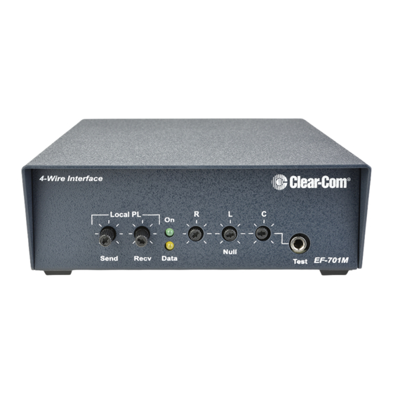
FRONT PANEL CONTROLS 4-Wire Interface Local PL Null Send Recv Data EF-701M Test Figure 1-5: Front panel of an EF-701M unit Local Send controls the audio signal level from the local 2-wire intercom (the system connected to this EF-701M) to the audio out of the 4-wire I/O. Local Receive controls the audio signal level from the audio in of the 4-wire I/O to the local 2-wire intercom. - Page 19 Sidetone Null Adjustment This set of three trimpots includes R=Resistance, L=Inductance, and C=Capacitance. These compensate for each component of the line impedance, providing the best null possible. To prevent damage to the level control and nulling trimpots, do not force them past their stop points. Power LED This green LED will illuminate when the EF-701M is receiving power from pin 2 of the party-line XLR connection.
-
Page 20: Rear Panel Settings And Connectors
Switch 1 adjusts the EF-701M’s connector settings for use with either 4-wire fiber (the ON position) or a matrix intercom (the OFF position). Switch 2 adjusts the EF-701M’s connector intercom levels for use with either Clear-Com equipment (the OFF position) or RTS-TW equipment (the ON position). Table 1-1 summarizes the mode switch settings. -
Page 21: 3-Pin Xlr Connector (Party Line I/O)
The female 3-pin XLR jack on the EF-701M’s back panel connects to the 2-wire party line. If a loop-through connection is needed, use a high quality “Y” cable like the Clear-Com SP-3. Note: Each (local) party-line channel must have one, but only one, termination. -
Page 22: Db-15 Connector
DB-15 Connector When mode-switch 1 is set to 4-wire mode (OFF), the DB-15 connects to additional interfaces or converters (or to another EF-701M). Two pins each are dedicated to audio in, audio out, data in, and data out. Shorting pins 8 and 15 together, or setting mode-switch 2 to ON adjusts the unit to respond to 20-kHz call signal instead of DC voltage and adjusts audio levels for connection to RTS TW lines. -
Page 23: Installation
CONNECTING THE EF-701M INTERFACE CONNECTING THE EF-701M TO A MATRIX PORT To connect the EF-701M directly to a Clear-Com Matrix frame port: 1. On the EF-701M’s back panel, set mode-switch 1 to the ON position. The Data LED will remain ON, except when the unit is being nulled. -
Page 24: Connecting The Ef-701M To A Modem
RTS-TW lines. If you set mode-switch 2 to the OFF position, the DC voltage call signal is selected and line levels are optimized for Clear-Com. Shorting pins 8 and 15 of the DB-15 connector on the EF-701M’s back panel will also select the 20-kHz call signal and adjust audio levels for connecting to RTS-TW lines. - Page 25 The four pairs of cable used for full operation include one each for audio in and audio out and one each for RS-422 data in and data out. Take care to wire the DB-15 or RJ-45 pins correctly. For added reference Figure 2-1 shows the pinout configuration.
- Page 26 Matrix RJ-45 Intercom Line 4-Wire Audio / Data 1 2 3 4 5 6 7 8 XLR-F Jump for TW Open for C-C + Matrix RS-422 from EF-701M (Not Used) - Matrix RS-422 from EF-701M - RS-422 Local Receive + Matrix Audio from Party Line - RS-422 Local Transmit + Matrix Audio to Party Line + RS-422 Local Receive...
-
Page 27: Connecting The Ef-701M To Rts-Tw Equipment
EF-701M). The audio channel carried on pin 2 of a TW line (Clear-Com or RTS) will not be connected through the EF-701M; however, it will not be negatively affected. -
Page 28: Levels
0 dBu range at the 4-wire interface. If different intercom brands are used on opposite ends of a pair of EF-701M units (RTS and Clear-Com for example), the controls may need to be adjusted outside of the normal range. Otherwise, more extreme settings could indicate a problem elsewhere in the system. -
Page 29: Nulling
NULLING “Sidetone” is the sound of the operator’s own voice in his or her headset or speaker. With interfaces, it is necessary to “null” (minimize) the sidetone when external party lines are connected over the secondary transmission media. Ideally, there should be no portion of the talk signal in the listen signal. -
Page 30: Adjusting The Null
Adjusting the Null Normally, the following adjustment is made once during installation. (If the configuration of the local party-line system changes substantially, it may be necessary to re-null the system for optimum performance.) 1. Connect all the local party-line devices for that channel together and to the EF-701M. 2.Plug into the front-panel earphone jack labeled “test.”... -
Page 31: Troubleshooting Tips For Nulling
If the “L” control is fully turned in either direction, it is likely that there is a problem in the external party line. With a Clear-Com party line connected, the “L” should be slightly to either side of the mid-pot position. -
Page 32: Internal Adjustments
INTERNAL ADJUSTMENTS The only user-adjustable internal setting is selection of the baud rate for the RS-422 data. The factory-set baud rate for the RS-422 data is 19.2 kilobits per second (19.2 kbps). For certain transmission schemes, the baud rate is internally selectable for 2400, 4800, or 9600 bits per second. - Page 33 6.Lift off the cover. 7.Make the necessary adjustments of jumpers P3 and P4 (shown in the following table). To set a jumper to the closed position, plug it onto both pins. To set a jumper to the open position, plug it onto only one of the pins. BAUD 1 BAUD 2 RATE...
-
Page 34: Transmission Methods
TRANSMISSION METHODS DIRECT CONNECTION There are many instances where twisted-pair cable is available for audio connections. This wiring is typically found in unused telephone cable in or between buildings. Figure 2-2 illustrates twisted-pair wiring connections. EF-701M EF-701M DB-9 Pins Twisted Pair Wiring DB-9 Pins - RS-422 Transmit - RS-422 Receive... -
Page 35: Fiber-Optic
Simply connect the 4-wire audio and 4-wire data between EF-701M units utilizing this cable. This will form a direct connection between the DB-15 connectors on a pair of EF-701M units. The PL systems at each end of the cable will require their own power and termination for their local channel. - Page 36 There are two basic modes of fiber-optic transmission. In a multimode fiber, the light travels through the fiber via multiple paths. In a single-mode fiber, the light travels in a single path. Depending on the equipment, single or multiple channels of audio, video, data, or a mix thereof can be multiplexed and carried in either one or both directions.
-
Page 37: Other Methods
LEDs as the light source. For dedicated use, Clear-Com has found that the FiberOptions 249B series (multimode, single channel) works well for most single channel applications. Range is up to 2.5 km (1.55 miles) with negligible signal loss at 1 km (0.62 mile) or less. - Page 38 2 - 1 6 E F - 7 0 1 M I N T E R F A C E...
-
Page 39: Maintenance
MAINTENANCE TROUBLESHOOTING TIPS Listed below are symptoms, causes, and solutions for some of the more common problems that may occur. E F - 7 0 1 M I N T E R F A C E 3 - 1... -
Page 40: Audio Troubleshooting Tips
Audio Troubleshooting Tips Symptom Cause Solution Squealing feedback, levels The local PL channel is not terminated. Check termination switches on PL too high, distortion, call equipment and set appropriately. (One signal stays on. termination per channel). Levels seem low even after The local PL channel has multiple Check termination switches on PL adjustment. - Page 41 1. Always begin a setup with these set to one end to the other. available on the modems. their nominal levels. 2. Clear-Com/RTS jumper is set 2. Reset jumper. incorrectly. Excessive noise or poor Various causes related to modems and Know the performance parameters of the frequency response.
-
Page 42: Data Troubleshooting Tips
Data Troubleshooting Tips Symptom Cause Solution Data LED is off even though 1. Problem in the wiring from the 1. Adjust wiring. units are connected at each DB-15 to the modem or problem end. with the transmission medium. 2. Baud rate or other modem 2. - Page 43 2. DB-15 is wired incorrectly at other 2. Check wiring. end. This will happen if an RTS-TW channel is connected at one EF-701M and a Clear-Com is connected at the other, but the DB-15 on the RTS end has not been wired properly.
-
Page 44: Nulling Troubleshooting Tips
Nulling Troubleshooting Tips Symptom Cause Solution No audio; green LED is off. EF-701M is not receiving power. EF-701M units at both ends of the connection must receive power from a local PL system. 3 - 6 E F - 7 0 1 M I N T E R F A C E... - Page 45 Symptom Cause Solution Unsatisfactory null. 1. Unstable PL system due to 1. Verify operational status of PL excessive cabling, a high number of equipment. stations, transformers connected across the intercom channel, or other PL equipment issues such as termination. 2. Remove EF-701M units from the network.
-
Page 46: Block Diagram
Block Diagram Figure 3-1: EF-701M Block Diagram TW Power Power Splitter Intercom Power Line Hybrid Null Receive Send 4-Wire 4-Wire Output Input Gain Nulling Adj. C-C Call Gain 20 kHz Call Earphone Adj. Send & Receive 20 kHz 200 Hz Phone Receive Call... -
Page 47: Glossary
GLOSSARY Category 3, 5, 5e, or 6 cable: EIA/TIA 568 category specification relating to the performance of network cabling. All are adequate for EF-701M wiring. The glossary gives definitions of technical CODEC : A device that enCODes and DECodes data. terms found throughout Drop(s) : A point or points in the party-line system where a beltpack or station is present. - Page 48 The EF-701M Interface connects 2-wire intercom systems or stations together over various 4-wire transmission media. In doing so, it converts a channel of standard 2-wire or TW party line to 4-wire audio and, at the same time, converts a DC-voltage call signal or 20-kHz call signal to RS-422 data.
- Page 49 Sidetone : The sound of your own voice transmitted through an earphone as you speak. Termination: A fixed load placed upon the Clear-Com party line to maintain stability. Two-wire audio : A single shielded-pair cable carrying a single channel of bidirectional (talk and listen) audio.
- Page 50 4 - 4 E F - 7 0 1 M I N T E R F A C E...
-
Page 51: Specifications
20kHz ±1KHz dBu is an absolute measurement. 0 dBu is referenced to Receive frequency: 20kHz 0.775 volts RMS ±500Hz Send level: >=-6dBu CLEAR-COM FORMAT Receive level: <=-20dBu LINE CHARACTERISTICS GENERAL CHARACTERISTICS Max Level Before Clipping >=20dBu Impedance: >=10KΩ Frequency response:... - Page 52 Distortion Party Line - Matrix (RTS setting) -12dB ± Party Line - Matrix <=0.5% Matrix - Party Line <=0.5% Matrix - Party Line (CC setting) -33dB ± Matrix - Party Line (RTS setting) -29dB ± Noise Party Line - Matrix <=-50dBu Matrix - Party Line <=-70dBu...
- Page 53 (3) Rotary Control Power Indicator (1) Green Notice About Specifications While Clear-Com makes every attempt to maintain the Data Indicator (1) Amber accuracy of the information contained in its product manuals, that information is subject to change without notice. Performance specifications included in this...
- Page 54 5 - 4 E F - 7 0 1 M I N T E R F A C E...
-
Page 55: Limited Warranty
LIMITED WARRANTY Vitec Group Communications (VGC) warrants that at the time of purchase, the equipment supplied complies with any specification in the order confirmation when used Return Material under normal conditions, and is free from defects in workmanship and materials during Authorization (RMA) the warranty period. -
Page 56: Technical Support
• UHF wireless IFB products have a limited warranty of one year. • UHF wireless intercom systems have a limited warranty of three years. • All other Clear-Com and Drake brand systems and products, including beltpacks, have a limited warranty of two years. -
Page 57: Warranty Repairs And Returns
Instructions for reaching VGC’s User Support Centers are given below. Telephone for Europe, Middle East and Africa: +49 40 6688 4040 or +44 1223 815000 Telephone for the Americas and Asia: +1 510 337 6600 Email: vitec.support@AVC.de Once the standard warranty period has expired, the User Support Center will continue to provide telephone support if you have purchased an Extended Warranty. -
Page 58: Non-Warranty Repairs And Returns
North America, Canada, Mexico, Caribbean & US Military Tel: +1 510 337 6600 Email: customerservicesUS@vitecgroup.com Asia Pacific & South America Tel: +1 510 337 6600 Email: customerservicesAPAC@vitecgroup.com VGC has the right to inspect the equipment and/or installation or relevant packaging. For latest contact information please refer to the Service and Support section at www.clearcom.com. -
Page 59: Extended Warranty
EXTENDED WARRANTY You can purchase an extended warranty at the time of purchase or at any time during the first two years of ownership of the product. The purchase of an extended warranty extends to five years the warranty of any product offered with a standard two-year warranty. - Page 60 OF USE, REVENUE, AND/OR PROFITS). SOME STATES DO NOT ALLOW THE EXCLUSION OR LIMITATION OF INCIDENTAL OR CONSEQUENTIAL DAMAGES OR THE LIMITATION ON HOW LONG AN IMPLIED WARRANTY LASTS, SO THE ABOVE LIMITATIONS MAY NOT APPLY TO YOU. IN ANY EVENT, TO THE MAXIMUM EXTENT PERMITTED UNDER APPLICABLE LAW, VGC'S LIABILITY TO CUSTOMER HEREUNDER SHALL NOT UNDER ANY CIRCUMSTANCES EXCEED THE COST OF REPAIRING OR REPLACING...
- Page 61 This limited warranty is not transferable and cannot be enforced by anyone other than the original consumer purchaser. This warranty gives you specific legal rights and you may have other rights which vary from country to country. W A R R A N T Y v i i...
- Page 62 v i i i E F - 7 0 1 M I N T E R F A C E...
Need help?
Do you have a question about the ENCORE EF-701M and is the answer not in the manual?
Questions and answers