
Related Manuals for Clear-Com Eclipse HX-Median


Summary of Contents for Clear-Com Eclipse HX-Median
- Page 1 User Guide| Eclipse HX-Median E-MADE User Guide Eclipse ® HX-Median User Guide A guide to the functions, use and setup of an Eclipse HX-Median intercom matrix Part Number:399G219 Rev A April 10, 2017...
- Page 2 Clear-Com, an HME Company. Clear-Com Offices are located in California, USA; Cambridge, UK; Dubai, UAE; Montreal, Canada; and Beijing, China. Specific addresses and contact information can be found on Clear-Com’s corporate website:...
-
Page 3: Table Of Contents
Eclipse HX-Median ............... 14 3.2.1 Chassis and assembly ............. 14 3.2.2 Power supplies ............... 18 3.2.3 Main features of the Eclipse HX-Median ........19 3.2.4 CPU card ................20 Interface cards ................20 3.3.1 MVX-A16 analog port card ............21 3.3.2... - Page 4 Auxiliary alarm lights .............. 65 5.7.5 Power supply lights ..............66 Connecting the matrix frame ............66 5.8.1 Eclipse HX-Median rear connector panels ........67 5.8.2 Connecting the CPU Card ............67 5.8.3 Connecting interface cards............68 E-MADI64 card ................70 E-MADI64 front panel lights and controls ........
- Page 5 User Guide| Eclipse HX-Median V-Series Panels on E-MADI (Multi-channel Audio Digital Interface) ..78 6.5.1 Configuring audio over MADI, the general case ......78 6.5.2 Configuring audio over Optocore/ProGrid MADIs ......79 Configuring binaural audio with E-MADI cards ........80 Configuring binaural panel audio in software ........
- Page 6 Make sure both devices are on the same subnet ....132 11.9.3 Reset the IP address of the Dante Controller......132 11.9.4 Link-local ................. 133 Maintaining the Eclipse HX-Median ..........134 12.1 Routine maintenance recommendations ........134 12.1.1 Cleaning the matrix frame ..........134 12.1.2...
- Page 7 User Guide| Eclipse HX-Median 14.6 E-MADI64 interface rear card ............ 146 14.7 E-MADI64 fiber cable ............... 146 14.8 E-MADI64 fiber transceiver ............147 14.9 E-MADI64 clock sources ............147 14.10 Fiber interface front card ............148 14.11 Fiber interface rear card ............148 14.12...
-
Page 8: Important Safety Instructions
User Guide| Eclipse HX-Median Important Safety Instructions Read these instructions. Keep these instructions. Heed all warnings. Follow all instructions. Do not use this apparatus near water. Clean only with dry cloth. Do not block any ventilation openings. Install in accordance with the manufacturer’s instructions. - Page 9 User Guide| Eclipse HX-Median into the apparatus, the apparatus has been exposed to rain or moisture, does not operate normally, or has been dropped. Warning: To reduce the risk of fire or electric shock, do not expose this product to rain or moisture.
- Page 10 User Guide| Eclipse HX-Median Safety Symbols Familiarize yourself with the safety symbols in Figure 1-1: Safety symbolsFigure 1-1 . These symbols are displayed on the apparatus and warn you of the potential danger of electric shock if the system is used improperly.
- Page 11 User Guide| Eclipse HX-Median Mains Power Cord Eclipse Matrix devices (matrix frames) are powered by an internal power supply. The cord to connect the internal power supply to the mains supply must conform to the following: The mains power cord shall have an IEC C13 connector at one end and a mains power plug at the other end.
-
Page 12: Introduction
At the heart of the system is the central matrix, comprising a matrix frame and the highly intuitive EHX configuration software, run from an external PC. This user guide describes how to use the Eclipse HX-Median, a 6RU matrix with 2 CPU and 7 interface card slots and 8 built-in interface module slots. -
Page 13: Overview
User Guide| Eclipse HX-Median Overview This chapter provides an overview of the Eclipse HX-Median matrix frame, including the interface cards and interface modules that can be fitted to the frame. Eclipse HX matrix frames There are four types of Eclipse HX matrix frame available from Clear-Com:... -
Page 14: Eclipse Hx-Median
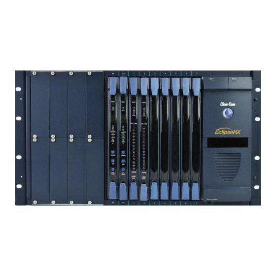
The matrix chassis is a metal rectangular box which measures six rack units (6RU) high and 19-inches wide (26.9 cm x 48.3 cm). The Eclipse HX-Median has twin power supplies, and slots for 2 CPU cards, 7 interface cards, and 8 interface modules. - Page 15 User Guide| Eclipse HX-Median Figure 3-1: Eclipse HX-Median front panel Page 15...
- Page 16 One power supply unit can power an entire matrix. The second unit provides a backup in case of failure or damage to the first unit. For more information, see 3.2.2 Power supplies. Table 2: Key to Eclipse HX-Median front panel Page 16...
- Page 17 User Guide| Eclipse HX-Median Figure 3-2: Eclipse HX-Median rear panel Page 17...
-
Page 18: Power Supplies
Eclipse HX-Median matrices may be fitted with XP (part 740101Z) or Power- One (part 720379Z) power supply units, depending on the date of manufacture. -
Page 19: Main Features Of The Eclipse Hx-Median
3.2.3 Main features of the Eclipse HX-Median Features of the Eclipse HX-Median matrix system include: A six rack-unit (6RU) frame. Full audio bandwidth throughout the signal chain, producing superior broadcast audio quality. The system maintains 24-bit depth, a sampling rate of 48 kHz, and 30 Hz to 22 kHz frequency response. -
Page 20: Cpu Card
For more information, see 4.4.3 Combining interface cards in the frame. 3.2.4 CPU card Two CPU cards are fitted to each Eclipse HX-Median system, in a master and slave relationship. The second CPU card provides redundancy in the case of outages or planned maintenance. The master CPU card: ... -
Page 21: Mvx-A16 Analog Port Card
3.3.1.1 Intelligent linking For intelligent linking, shielded CAT5 cable is run from a port on one Eclipse HX- Median matrix to a port on a second Eclipse HX-Median matrix to form a trunkline connection. 3.3.2 E-FIB fiber card E-FIB fiber interfaces connect Eclipse HX matrices together to provide a high speed, dual redundant link to transfer audio samples and data between systems. -
Page 22: E-Que E1/T1 Interface Card
User Guide| Eclipse HX-Median 3.3.3 E-QUE E1/T1 interface card The E-QUE E1/T1 interface allows the Eclipse HX-Median to connect to FreeSpeak/CellCom/ FreeSpeak II antennas, FreeSpeak/CellCom/ FreeSpeak II antenna splitters, and E1 and T1 trunk lines. Each E-QUE interface card set comprises: ... -
Page 23: Interface Card
3.3.7 E-DANTE64-HX interface card This is a Clear-Com matrix interface card that is enabled to work with Dante network protocols and software. Using the E-Dante64 card you can transport many channels of high quality audio via a Clear-Com matrix to multiple Dante... -
Page 24: Interface Modules
AES-3 option card. It may also be used with AES-3 compliant third party equipment. Note: Additional interface modules may be added to the Eclipse HX-Median, using separate interface module frames such as the IMF-3 and IMF-102. For more information, see the dedicated user guide / manual for that particular interface frame. -
Page 25: Ehx Configuration Software
EHX software can store an almost unlimited number of complete system configurations (the number is only limited by the available memory space on the PC). You can download the configurations to the Eclipse HX-Median as required. EHX 8.5.1 runs on the following versions of Windows: ... - Page 26 User Guide| Eclipse HX-Median i-Series panels, including expansion panels. Note: For more information about installing, using and maintaining user panels, and connecting user panels to the matrix, see either: The V-Series Panels Guide. The i-Series Panels Guide...
-
Page 27: Installing The Eclipse Hx-Median
Note: The Eclipse distributor is not responsible for shipping damage. 4.1.2 Unpacking the System When the Eclipse HX-Median system is received the circuit cards (CPU cards and interface cards), power supplies, and rear-connector panels are pre-installed in the matrix chassis. - Page 28 ON position. The battery is now powered. Figure 4-1: CPU card with detail of CON9 jumper plugs Eclipse HX-Median CPU cards are fitted with a socketed battery, normally a Renata CR2477N with a capacity of 950mAh and a life of approximately 247 days.
-
Page 29: Installing The Eclipse Hx-Median
LED. If EHX is logging, then the following message will appear in the log. Non Volatile Data is invalid - Please check Battery Voltage If on successive power downs of the Eclipse HX-Median frame the above state is detected, and the message appears in EHX logs, then it is advisable to check the health of the CPU card on board battery, which should be nominally at least 2.8V. -
Page 30: Installing The Power Supplies
AC mains power using the IEC power connectors on the matrix’s rear panel. A fully equipped Eclipse HX-Median matrix (2 CPU cards, 7 interface cards and 8 interface modules) requires 100 - 240 VAC at 50 - 60 Hz with a maximum dissipation of 300W. -
Page 31: Installing Cpu Cards
The screws are attached and cannot be removed. Install the new rear panel by sliding the card into the card’s guides at the top and bottom of the Eclipse HX-Median chassis. Tighten all of the screws on the rear panel. -
Page 32: Hot Patching Cpu Cards
User Guide| Eclipse HX-Median Figure 4-2: CPU card DIP switches set for normal operation Note: Store spare CPU cards in unused slots in the matrix or in electrically insulated packaging such as anti-static heavy duty plastic bags. To insert a CPU card in the matrix: Carefully place the card in the appropriate slot. - Page 33 User Guide| Eclipse HX-Median RESET The two power supplies are lit green to indicate that they are working. +3.3V IPC (Interprocessor Dot matrix display indicates communication) LED is lit which of the four stored green to indicate that the two...
-
Page 34: Installing Interface Cards
4.4.3 Combining interface cards in the frame The Eclipse HX-Median can allocate up to 496 audio ports in total. However, the number of ports that you actually use will depend on the combination of interface cards you fit to the frame. -
Page 35: Static Sensitivity
User Guide| Eclipse HX-Median More ports can be utilized on the Eclipse HX-Median by using higher capacity interface cards, such as the E-MADI64 card. For example, if you installed 5 E- MADI64 cards, using 64 audio ports, you could add a further 2 MVX-A16 cards. -
Page 36: Hot Patching (Hot Plugging)
User Guide| Eclipse HX-Median 4.4.5 Hot patching (hot plugging) Interface cards are hot patchable and self initializing, which means that a faulty card can be removed and replaced while the system is powered. Hot patching (also known as hot plugging) has no effect on any part of the system’s operation, except the MVX-A16 analog card’s assigned sixteen ports. -
Page 37: Wiring Audio Devices To The Matrix Frame
User Guide| Eclipse HX-Median RESET One of the four power-supply lights Is lit to indicate that the associated power supply is operating properly. +12V -12V +3.3V The VOX lights corresponds to the card’s 16 ports. When lit, a VOX light indicates the audio... -
Page 38: Wiring Panels To The Matrix Frame
-12, -9, -6, -3, 0, +3, +6, +9, +11 dB. Figure 4-6: Direct matrix frame port connection Clear-Com recommends the use of shielded cable. Note: The Eclipse HX Installation Guide gives complete details about wiring audio devices to the matrix. The installation manual also discusses RJ-45 cables and other types of cable required for system installation. -
Page 39: Single-Pair Digital
User Guide| Eclipse HX-Median Figure 4-7: Wiring the matrix to an analog panel using RJ-45 4.6.2 Single-pair digital Single-pair digital wiring is accomplished with double-shielded 24 AWG conductor CAT-6E enhanced STP cable. Pair 1 transmits and receives multiplexed digital and analog between the matrix and the panel. -
Page 40: Wiring Cpu Card Interfaces
Figure 4-8: Wiring the matrix to a digital panel using RJ-45 Note: The above wiring diagram refers to DIG-2 and is shown as an example only (DIG-2 panels are not compatible with the Eclipse HX-Median. Wiring CPU card interfaces The CPU card holds the circuitry for connecting to, and communicating with, the following interfaces: ... -
Page 41: Cpu Card Interface Connectors
User Guide| Eclipse HX-Median 4.7.1 CPU card interface connectors GPI/ RLY INTERFACE RS-232 ALARM I/O GP-OUT GP-IN LAN1 LAN2 Figure 4-9: CPU card interface connectors Page 41... - Page 42 If this port is used a ferrite core must be added to the socket end of each cable. A suitable ferrite core is Würth Electronik part: 74271132. Clear-Com recommends the use of shielded cable. For wiring pinout information for GPI/RLY interfaces, see: ...
- Page 43 User Guide| Eclipse HX-Median Matrix Frame Computer Serial Port DB-9F "IBM-PC RS-232" Cable Connector DB-9M Cable Connector Receive (RXD) Transmit (TXD) Transmit (TXD) Receive (RXD) Ground (GND) Figure 4-10: Wiring the matrix DB-9M to the PC DB-9F Matrix Frame Computer Serial Port DB- "IBM-PC RS-232"...
- Page 44 A logic low or an open circuit means that the matrix will not detect an alarm condition. Pin 1 is a voltage source out of the Eclipse HX-Median matrix. It is connected through a 10Kohm pull-up resistor to the +5 V supply rail inside the Eclipse HX-Median matrix.
- Page 45 Note: If the GP-OUT port is used on an Eclipse HX-Median matrix fitted with XP power supplies (part 740101Z) the following filter must be fitted between the PROC-RCC socket and the cable:...
- Page 46 User Guide| Eclipse HX-Median the power supplies are changed to Power-One units the filter must be removed before the matrix is powered up. The DB-25 connector labeled GP OUT connects the matrix to eight double-pole double-throw (DPDT) relays with contact ratings of 30 VDC at 1A.
- Page 47 User Guide| Eclipse HX-Median a panel’s speaker off. The function to perform and the panel upon which it is performed is configured using EHX. A shielded cable should be used. The general-purpose inputs operate in one of two modes: the opto-isolated mode or the non-isolated mode.
- Page 48 User Guide| Eclipse HX-Median isolator drive line contains a 1.5 kOhm resistor to limit the current through the opto-isolator. Therefore the input pins can be connected directly to a ground pin to cause an active input. The voltage level at the external input pin should not be allowed to go below ground or above +6 V with respect to ground.
- Page 49 If this port is used a ferrite core must be added to the socket end of each cable. A suitable ferrite core is Würth Electronik part: 74271132. Clear-Com recommends the use of shielded cable. Local Area Network connector (LAN2) The LAN1 and LAN2 connectors have standard Ethernet pin assignments.
-
Page 50: Dse1/T1 Matrix To Matrix Crossover Cable Connections
User Guide| Eclipse HX-Median 4.7.2 DSE1/T1 Matrix to Matrix crossover cable connections For E1 and T1 direct matrix to matrix connections the CAT5 crossover cables should be wired, as shown in the table below: Matrix 1 Pin Description Matrix 2 Pin... - Page 51 User Guide| Eclipse HX-Median DECTSYNC- Table 9: E1 pinout for connecting a FreeSpeak / CellCom / FreeSpeak II antenna or splitter Matrix 1 Pin Description Matrix 2 Pin Not connected Not connected Not connected Not connected Table 10: E1 to FreeSpeak / CellCom / FreeSpeak II antenna or splitter...
-
Page 52: Using The Eclipse Hx-Median
If you create more than one configuration, you can store the unused configurations on the computer’s hard disk or on CD-ROM for later use. Note: The CPU card in the Eclipse HX-Median stores up to four complete configurations. You can apply a configuration directly from the CPU card or from the connected PC. -
Page 53: Using The Cpu Card Ethernet Ports
User Guide| Eclipse HX-Median Using the CPU card Ethernet ports The CPU card Ethernet ports are normally connected to a LAN and used to communicate with clients such as EHX and Production Maestro. The Ethernet port functionality depends on the IP address setup. - Page 54 The replacement of a port card. The replacement of a panel. An Eclipse HX-Median system operates with either one or two CPU cards. When a second card is installed, that card stores the four configurations in its RAM as a backup to the main card. If the main card is removed or becomes non- operational for any reason, the system will automatically switch to the second card as backup.
-
Page 55: Cpu Card Lights And Controls
User Guide| Eclipse HX-Median CPU card lights and controls RESET +3.3V MASTER LAN A LAN B IN SYNC CONFIG RESET Figure 5-1: CPU card lights and controls Page 55... - Page 56 User Guide| Eclipse HX-Median Key to CPU card lights and controls Feature Description RESET button Pressing the RESET button causes the CPU card to stop its current activity and to restart. The same configuration that was active before the system was reset will be active after the system was reset.
- Page 57 CPU cards are exchanging information. Master Light An Eclipse HX-Median system can have two CPU cards, although the system will operate with only one. If the primary card becomes unavailable for any reason, the second card can serve as backup while the primary card is repaired or replaced.
- Page 58 User Guide| Eclipse HX-Median When the desired number is displayed, press and hold the CONFIG button until the display stops flashing. This should take about three seconds. The selected configuration has now been activated. The CPU card includes an additional, embedded configuration,...
-
Page 59: Using The Embedded Configuration
User Guide| Eclipse HX-Median The same configuration that was active before the system was reset will be active after reset. When the cards and connected audio devices reset, they momentarily stop their current activity and restart. During this process configuration information is downloaded to the cards and audio devices from the CPU card’s non-volatile RAM. -
Page 60: Mvx-A16 Analog Card Front-Panel Lights And Controls
User Guide| Eclipse HX-Median MVX-A16 analog card front-panel lights and controls RESET +12V -12V +3.3V ACTIVE VOX FRAME STATUS DATA Figure 5-2: MVX-A16 analog card front panel lights and controls Page 60... - Page 61 User Guide| Eclipse HX-Median Key to MVX-A16 analog card lights and controls Feature Description RESET button Pressing the RESET button causes the card and all connected audio devices to momentarily stop their current activity and to restart. The card’s “frame data” light goes off when the reset starts and comes back on when the reset is complete.
-
Page 62: Diagnosing Power Supply Problems
Table 12: Key to MVX-A16 analog front panel lights and controls Diagnosing power supply problems The Eclipse HX-Median has two Euro Cassette power supply units. One power supply unit can power an entire matrix. The second unit provides a backup in case of an equipment failure. - Page 63 User Guide| Eclipse HX-Median Euro Cassette Euro Cassette Power Supply 1 Power Supply 2 Euro Cassette Alarm lights Power supply lights (green when lit): Alarm lights +12 V light (red when lit): +5 V light +3.3 V light Main alarm light...
-
Page 64: Conditions That Cause An Alarm
User Guide| Eclipse HX-Median Note: Power-One power supply units (part 720379Z) should not be adjusted. 5.7.1 Conditions that cause an alarm The following conditions trigger an alarm: If any of the voltages produced by the first power supply unit fall below normal levels. -
Page 65: Auxiliary Alarm Lights
User Guide| Eclipse HX-Median stops flashing when all original sources triggering the alarm are corrected. If a new alarm condition or conditions occur before the original alarm conditions are corrected, the internal buzzer and relay contacts will not reactivate. They will only reactivate after all original alarm conditions are corrected. -
Page 66: Power Supply Lights
+12 V, –12 V, +5 V, and 3.3 V power. Connecting the matrix frame Note: For detailed information about connecting the matrix to panels, interfaces and other devices, see 4 Installing the Eclipse HX-Median Page 66... -
Page 67: Eclipse Hx-Median Rear Connector Panels
User Guide| Eclipse HX-Median The Eclipse HX-Median matrix frame connects to devices such as the external computer that runs the EHX configuration software, panels, interfaces, and other matrices through its rear-panel hardware connectors, often called ports. These connectors are housed in modular removable panels. Each panel is associated with a corresponding front-panel circuit card. -
Page 68: Connecting Interface Cards
CPU cards is acting as master will work in conjunction with this card. All other front cards, however, require their own rear-connector panel. Note: For detailed information about connecting the matrix to panels, interfaces and other devices, see 4 Installing the Eclipse HX-Median. 5.8.3 Connecting interface cards... - Page 69 Each rear connector panel associated with an E-FIB interface holds two fiber ports (TXVRA and TXVRB). Note: For detailed information about connecting the matrix to user panels, interface modules and other devices, see 4 Installing the Eclipse HX-Median. Page 69...
-
Page 70: Madi64 Card
User Guide| Eclipse HX-Median E-MADI64 card This chapter describes the E-MADI64 card. The E-MADI64 is a MADI (Multichannel Audio Digital Interface) card, providing up to 64 duplex channels of AES3 digital audio over a coaxial cable or fiber pair between compatible devices. The card supports both direct and trunk connections. -
Page 71: E-Madi64 Front Panel Lights And Controls
User Guide| Eclipse HX-Median E-MADI64 front panel lights and controls RESET +3.3V LOCK VID WRD 44.1 CHANNELS ERROR ACTIVE E-MADI Figure 6-1: E-MADI64 front panel lights and controls Page 71... - Page 72 User Guide| Eclipse HX-Median Note: Figure 25 shows an unconfigured E-MADI64 card, when all lights are lit to indicate their location. Note: On a card with a clock source and MADI connections (where the received MADI signal matches the card set up), the following lights are lit: the Lock source...
- Page 73 User Guide| Eclipse HX-Median Channel LEDs on the front of the E-MADI card will oscillate Note: between two channel numbers when the number of channels received differs from the number of channels set in EHX. Diagnostics Active LED The Active (frame data) LED flashes green (1:1 at 0.5Hz) to...
-
Page 74: E-Madi64 Rear Panel Connectors
User Guide| Eclipse HX-Median E-MADI64 rear panel connectors E-MADI MADI MADI IN MADI OUT CLOCK Figure 6-2: E-MADI64 rear panel connectors Page 74... -
Page 75: Madi Channels
Note: The channel modes for the E-MADI64 are 32, 56 and 64. For more information, see Table 16: E-MADI 64 channel modes. Each MADI audio channel: Carries one (or a mixture of) any of the 512 Eclipse HX-Median backplane timeslots. Is 24 bits in length. -
Page 76: Madi Channel Labeling
Setting up the E-MADI64 card To set up the E-MADI card: With the Eclipse HX-Median powered off, insert the E-MADI front and rear cards into the frame. Note: The number of E-MADI64 cards you can fit to the matrix frame is limited by the available port count. -
Page 77: Connecting A Word Clock Source
User Guide| Eclipse HX-Median Configure EHX settings for the E-MADI64 cards. Standard EHX settings (including VOX and In-use tally) are applicable to all E-MADI64 channels. Note: Card Properties permits sample rate selection when synching to video signals. It is only used when not using the Word Clock Source Sync (see below). -
Page 78: Connecting E-Madi 64 Audio (Using Coaxial Or Fiber Cable)
User Guide| Eclipse HX-Median 6.4.3 Connecting E-MADI 64 Audio (using Coaxial or Fiber cable) When you connect the external E-MADI64 Audio (using Coaxial or Fiber cable) to the rear of theE-MADI64 card: The sample rate and the number of configured ports is indicated by a solid green LED on the front of the E-MADI64 card. -
Page 79: Configuring Audio Over Optocore/Progrid Madis
User Guide| Eclipse HX-Median even numbered ports may be left unused (Empty), leaving the panel with only the main channel audio (channel A). See Figure 6.3. Note: It is not necessary to define a block of panels as consecutive odd numbers. For example, ports 1,3,9,11,51 could be defined as panels, with all the other slots unused or used for other purposes if required. -
Page 80: Configuring Binaural Audio With E-Madi Cards
User Guide| Eclipse HX-Median the main and aux channels are not defined on adjacent ports of the MADI. See Figure 6.4. In all cases, when using a router such as ProGrid, ensure that the configuration of the E-MADI card and the configuration of the ProGrid matrix are consistent with each other. -
Page 81: Configuring Binaural Panel Audio In Software
User Guide| Eclipse HX-Median Use a headset with a minimum of a 5-pin input (use with an XLR5 or 7 adapter). Configuring binaural panel audio in software The main audio channel and the auxiliary audio channel need to be directed to the desired ports. -
Page 82: Binaural Audio Over Optocore/Progrid Madis
User Guide| Eclipse HX-Median 6.7.2 Binaural audio over Optocore/ProGrid MADIs Optocore/ProGrid MADIs allow each channel of the MADI to be routed individually to any channel of any destination. The AES streams do not have to be routed and configured in pairs. The ProGrid equipment allows fully flexible routing and it is possible to mix close packed mono and conventional stereo pairs on one MADI interface. -
Page 83: Upgrading The E-Madi64 Card
User Guide| Eclipse HX-Median Select Configuration>Panels>Audio Mixer>Layout Basic Settings>Layout Binaural coax/AES Figure 6-6 Set binaural viewing options in the audio mixer Set audio routes as required (see EHX User Guide, 8. Audio Mixer for more information). Upgrading the E-MADI64 card... -
Page 84: Fib Fiber Card
If fiber interfaces are fitted to any matrix in a linked system all the linked matrices must be reset to ensure that all matrices correctly recognize the new hardware. Note: For an overview of the Eclipse HX-Median, see 3 Overview. Page 84... -
Page 85: E-Fib Front Panel Lights And Controls
User Guide| Eclipse HX-Median E-FIB front panel lights and controls RESET +3.3V PROC FRONT REAR TXVRA ACT LINK ERR TXVR TXVRB ACT LINK ERR TXVR STATUS FRAME DATA Figure 7-1: E-FIB front panel lights and controls Page 85... - Page 86 User Guide| Eclipse HX-Median Key to E-FIB front panel lights and controls Feature Description RESET button Pressing the RESET button causes the card and all links to momentarily stop their current activity and to restart. The card’s frame data light goes off when the reset starts and comes back on when the reset is complete.
- Page 87 User Guide| Eclipse HX-Median This LED indicates whether a link has been established on the secondary fiber optic circuit (transceiver B). When illuminated a link is present. TXVR LED This LED indicates when data is being transmitted on the secondary circuit. It is illuminated when data is present on the circuit.
-
Page 88: E-Fib Rear Panel Lights And Connectors
User Guide| Eclipse HX-Median E-FIB rear panel lights and connectors +3.3V TXVRB Transceiver lasers TXVRA Figure 7-2: E-FIB rear panel lights and connectors Warning: Eye Safety This laser based single mode transceiver is a Class 1 Laser product. It complies with IEC 60825-1/A2:2001 and FDA performance standards for laser products (21 CFR 1040.10 and 1040.11) except for deviations pursuant to Laser... - Page 89 User Guide| Eclipse HX-Median should only be removed in order to fit the fiber optic cable. Replace the plug when the cable is unplugged. Primary and secondary fiber ports are reversed with respect to the front panel indicators. Care should be taken when connecting or disconnecting cables to ensure that they are connected correctly and not reversed.
-
Page 90: Configuring A Fiber Optic Connection
User Guide| Eclipse HX-Median System 1 System 2 Primary ring Redundant ring TXVRB TXVRB TXVRA TXVRA System 3 TXVRB TXVRA Figure 7-3: Primary and redundant ring configuration Configuring a fiber optic connection There are a number of ways that optical connections can be made between systems depending on the level of redundancy required. -
Page 91: Simplex Fiber Cabling
User Guide| Eclipse HX-Median Simplex fiber cabling 7.4.1 Single card set redundancy In this scenario, each matrix contains one fiber-optic Linking card set (see Figure 7-4: Ring topology: single card set redundancy ). This approach still affords fiber connection redundancy since each rear card houses two fiber-optic transceivers. -
Page 92: Dual Card Set Redundancy
User Guide| Eclipse HX-Median The self-healing mechanism is performed automatically by the Fiber Linking Card. Switching to the secondary ring will cause audio breaks or disturbances and temporary loss of crosspoint data. If a single fiber connection is lost on both rings the nodes adjacent to the failures will loop-back their connections to the failed cables healing the rings. -
Page 93: Fault Tolerance
User Guide| Eclipse HX-Median Note: In the absence of an Uninterrupted Power Supply this configuration will not protect against loss of the node or Matrix Frame itself. 7.4.2.1 Parallel operation The cabling and operation of both cards sets is the same as described in 7.4.1 Single card set redundancy. - Page 94 User Guide| Eclipse HX-Median 7.4.3.1 Single Card Set Redundant System: fiber redundancy In all fault cases involving cable faults or loss of nodes on the ring the remaining nodes may experience audio breaks or disturbances and loss of crosspoint information or data.
- Page 95 User Guide| Eclipse HX-Median System #1 System #2 System #3 TX2- E-FIB TX2- E-FIB TX2- E-FIB card#1 - RX2 card#1 - RX2 card#1 - RX2 TX1- E-FIB TX1- E-FIB TX1- E-FIB card#1 - RX1 card#1 - RX1 card#1 - RX1...
-
Page 96: Que E1/T1 Card
Note: You do not require an Ethernet cable connected to the E-QUE card LAN port for the card to function correctly. For an overview of the Eclipse HX-Median matrix, see 3 Overview. Page 96... -
Page 97: E-Que Front Panel Lights And Controls
User Guide| Eclipse HX-Median E-QUE front panel lights and controls RESET +3.3V STATUS LAN DATA LINK Figure 8-1: E-QUE front panel lights and controls Page 97... - Page 98 User Guide| Eclipse HX-Median Key to E-QUE front panel lights and controls Feature Description RESET button Pressing the reset button causes the card and all links to momentarily stop their current activity and to restart. During the reset, configuration information downloads to the card from the CPU card.
-
Page 99: E-Que Rear Panel Connectors
User Guide| Eclipse HX-Median E-QUE rear panel connectors Ref in DECT Ref out E-QUE 1 – 4 5 – 8 Figure 8-2: E-QUE rear panel connectors Page 99... -
Page 100: E-Que Interface Card Applications
User Guide| Eclipse HX-Median Key to E-QUE rear panel connectors Feature Description LAN port (RJ-45) The LAN port is used for diagnostic purposes. DECT sync ports: DECT Ref in DECT Ref out E1 / T1 Port 1 - 4(RJ-45) E1 / T1 Port 5 - 8 (RJ-45) -
Page 101: Freespeak/Cellcom/Freespeak Ii Application
User Guide| Eclipse HX-Median 4.9 E1 to FreeSpeak® / CellCom® / FreeSpeak II™ antenna straight cable connection. 8.3.1 FreeSpeak/CellCom/FreeSpeak II application The E-QUE interface cards can be configured for FreeSpeak/CellCom/FreeSpeak II use in two modes, depending on whether antennas or splitters are to be connected. - Page 102 User Guide| Eclipse HX-Median Figure 8-4: E-QUE card splitter connection Each antenna can handle up to five beltpacks simultaneously and switch service between antennas under control of the matrix as the beltpack user moves around the site. The DC In power connector is used to locally power the transceiver/antenna with the supplied universal power supply.
-
Page 103: E1 Trunk And Direct Modes
User Guide| Eclipse HX-Median Figure 8-5: Multiple matrices (matrix frames) with DECT Sync Interconnect Note: All connections are made using CAT5 cable and it is recommended that shielded cable is used. Note: If an E-QUE interface is fitted in the matrix with antennae or splitters connected... - Page 104 User Guide| Eclipse HX-Median Long Haul Receive Signal Level. E1 120 Ohm Transmit Pulse Amplitude. Balanced. 120 Ohm Line Impedance. No Signaling. G.722 or G.711 64 kbit/s Audio Encoding. Tx Clock locally generated.
- Page 105 User Guide| Eclipse HX-Median Figure 8-6: Matrix to Matrix direct E1 Trunking E1 trunking between matrices can also be achieved over an E1 network, as shown Figure 8-7: E1 Trunking with an E1 Network. In this case E1 ports 1 and 5 of the E-QUE interface are connected using standard straight-through CAT5 cables rather than crossover CAT5 cables.
-
Page 106: T1 Trunking
User Guide| Eclipse HX-Median Figure 8-8: Matrix to Third Party E1 connection The CAT5 cable connecting the E1 port on the E-QUE rear card may be a crossover cable or a straight-through cable depending on the requirements of the third party equipment. The E-QUE interface should be set to Direct in EHX. - Page 107 User Guide| Eclipse HX-Median G.722 or G.711 64 kbit/s Audio Encoding. Tx Clock locally generated. Rx Clock Line Recovered. Figure 8-9: Matrix to Matrix T1 Trunking T1 trunking between matrices can also be achieved over an E1 network as shown in Figure 8-10: T1 Trunking using an E1 Network.
-
Page 108: Trunking Failover
User Guide| Eclipse HX-Median Figure 8-10: T1 Trunking using an E1 Network Trunking failover Where the E1/T1 trunking has been configured with redundant trunks audio will be switched from the primary trunk to the backup trunk when a failure is detected. -
Page 109: Card For Ip-Based Connections
User Guide| Eclipse HX-Median IVC-32 card for IP-based connections The IVC-32 (Instant Voice Communication) interface card provides the Eclipse HX-Median with connectivity over IP to V-Series IP panels and Concert servers. Each IVC-32 interface card comprises: A front card with a reset button and various status indicators (including status LEDs for power, port activity and LAN status). -
Page 110: Front Panel Lights And Controls
User Guide| Eclipse HX-Median IVC-32 front panel lights and controls RESET +3.3V STATUS LAN DATA LINK Figure 9-1: IVC-32 front panel lights and controls Page 110... - Page 111 User Guide| Eclipse HX-Median Key to Figure 41: IVC-32 front panel lights and controls Feature Description RESET button Pressing the reset button causes the card and all links to momentarily stop their current activity and to restart. During the reset, configuration information downloads to the card from the CPU card.
-
Page 112: Rear Panel Connectors
User Guide| Eclipse HX-Median IVC-32 rear panel connectors Ref in DECT Ref out IVC-32 1 – 4 5 – 8 Figure 9-2: IVC-32 rear panel connectors Page 112... -
Page 113: Interface Applications
V-Series IP Panels V-Series panels with V5.1 or later software may be enabled to communicate with an Eclipse HX-Median matrix over an IP network using the IVC-32 interface card. The advantage of using IP communication is that it enables remote panels to communicate over an existing local (LAN) or wide area (WAN) network rather than requiring a dedicated link. - Page 114 User Guide| Eclipse HX-Median Figure 9-3: IP communication using an IVC-32 interface card Page 114...
-
Page 115: Metering Card
DECT sync in and out (not used) and a LAN port used for the IP connection. Note: An Ethernet cable must be connected to the LMC-64 interface LAN port for the card to function correctly. Note: For an overview of the Eclipse HX-Median, see 3 Overview. Page 115... -
Page 116: Front Panel Lights And Controls
User Guide| Eclipse HX-Median 10.1 LMC-64 front panel lights and controls RESET +3.3V STATUS LAN DATA LINK Figure 10-1: LMC-64 front panel lights and controls Page 116... - Page 117 User Guide| Eclipse HX-Median Key to IVC-32 front panel lights and controls Feature Description RESET button Pressing the reset button causes the card and all links to momentarily stop their current activity and to restart. During the reset, configuration information downloads to the card from the CPU card.
-
Page 118: Rear Panel Connectors
User Guide| Eclipse HX-Median 10.2 LMC-64 rear panel connectors Ref in DECT Ref out LMC-64 1 – 4 5 – 8 Figure 10-2: LMC-64 rear panel connectors Page 118... -
Page 119: Interface Applications
User Guide| Eclipse HX-Median Key to LMC-64 rear panel connectors Feature Description LAN port (RJ-45) DECT sync ports: DECT Ref in (Not used) DECT Ref out (Not used) E1 / T1 Port 1 - 4 (Not used) E1 / T1 Port 5 - 8(Not used) -
Page 120: Dante64-Hx Card
E-Dante64-HX card This section contains information about audio networking using an E-DANTE64- HX interface card. This is a Clear-Com matrix interface card that is enabled to work with Dante network protocols and software so that you can transport many channels of high quality audio via a Clear-Com matrix to multiple Dante enabled devices using standard Ethernet network structure (up to 64 channels per E-DANTE64 card). -
Page 121: Example Applications
User Guide| Eclipse HX-Median 11.1 Example applications 11.1.1 Interruptible Foldback (IFB) over Dante Figure 11-1 IFB over Dante Page 121... -
Page 122: Live Performance Interface With Digital Intercom
User Guide | Eclipse HX Omega 11.1.2 Live performance interface with digital intercom Figure 11-2 Live performance interface with Clear-Com digital intercom Page 122... -
Page 123: Using The E-Dante64-Hx Card
User Guide | Eclipse HX Omega 11.2 Using the E-DANTE64-HX card To route audio using a Clear-Com Dante card you must already have the Audinate Dante Controller installed on your PC (or similar device that can set up Dante routes). The Dante Controller can be downloaded from the Audinate website. -
Page 124: E-Dante64-Hx Front Panel Lights And Controls
User Guide | Eclipse HX-Median 11.3 E-DANTE64-HX front panel lights and controls Feature Description Reset button Pressing the Reset button causes the card and all links to momentarily stop their current activity and to restart. The flashing green Active light goes off when the reset starts and comes back on when the reset is complete. - Page 125 User Guide | Eclipse HX-Median Active LED The Active (matrix data) LED flashes green (1:1 at 1Hz) to indicate successful communication between the E-DANTE64-HX interface and the CPU card. This LED will flash twice as fast while a card is being upgraded and firmware is being installed (EHX firmware only, the light will stay as normal while Dante firmware is being installed).
-
Page 126: E-Dante64-Hx Rear Panel Lights And Controls
Feature Description Secondary network connector RJ45 See Note below. Secondary network connector Fiber In this slot you will install a Clear-Com SFP/Mini- GBIC. See Specifications section for details. Secondary Fiber connection LEDs green LED indicates that the network (Primary or Secondary) is successfully connected. -
Page 127: Network Configuration
The E-Dante64 card IP address is set by the Dante controller. This IP address is different from the main Eclipse Matrix (LAN) IP address. Clear-Com recommends that the Eclipse Matrix (LAN) IP address uses a fixed/static IP address. 11.6 Installing a replacement or backup card... -
Page 128: Upgrading Your E-Dante64-Hx Card
The upgrade process for each of the two modules on the card (EHX and Dante) is different. The two processes are outlined below. Note: When upgrading your E-Dante64 card, only use the Clear-Com supplied upgrade files for both (A: EHX) ClearCom - App, Boot, DSP, FPGA: xxxxxx.FWC files (B: Dante) ClearCom [Brooklyn]: xxxxxx.dnt file. - Page 129 User Guide | Eclipse HX-Median Right click on the matrix to be upgraded and select Firmware > Update Firmware > Card. Navigate to where the E-Dante64 upgrade file is stored and click to upload. There are 4 possible upgrade file types.
-
Page 130: Upgrade Dante Firmware
E-Dante64 through the matrix, using EHX) and locally upgradeable, using Xilinx software, a PC and a Xilinx download cable. The process is the same as for a Clear-Com MADI card. For more information, see the Eclipse HX Upgrade Guide and refer to the section on MADI. -
Page 131: Troubleshooting: I Need To Find The E-Dante64 Card's Ip Address
User Guide | Eclipse HX-Median 11.9 Troubleshooting: I need to find the E-Dante64 card’s IP address In most cases the E-Dante64 card will be discovered by the Dante Controller and be available for configuration in the controller’s Routing page. Cards that have been ‘misplaced’ and are not visible in the routing screen are those that have been configured with a static IP address that falls outside the subnet which the PC hosting the controller is on. -
Page 132: Make Sure Both Devices Are On The Same Subnet
User Guide | Eclipse HX-Median Figure 11-5 Find IP address 2 11.9.2 Make sure both devices are on the same subnet In order to be able to configure the E-Dante card as usual, you must make sure that the PC hosting the controller is in the same IP range (subnet) as the card. -
Page 133: Link-Local
User Guide | Eclipse HX-Median Figure 11-6 Reset IP address 11.9.4 Link-local The link-local IP range is a special case (169.254.1.0 – 169.254.254.255). The Dante Controller will NOT see an E-Dante64 card with a link-local IP address if the PC hosting it is not set to the link-local IP range also. In this case, you need to change the PC’s IP address to a value in the link-local range... -
Page 134: Maintaining The Eclipse Hx-Median
Once the circuit board has been identified, it can be either repaired or replaced. Note: For an overview of the Eclipse HX-Median, see 3 Overview. Servicing instructions are for use by qualified personnel only. -
Page 135: Fail-Safe Modes
One of each type of interface in the system. 12.2 Fail-Safe modes High reliability is one of the main objectives of the Eclipse HX-Median system design. The following features of the system minimize the effects of a component failure. -
Page 136: Onboard Processors
Backplane connector malfunctions are rare, but should be considered as possibilities. Note: Clear-Com may ship a spare matrix to use while the damaged matrix is being repaired depending on the support status. For more information, see your warranty and support documentation. - Page 137 The matrix can be returned to Clear-Com for investigation or repair. In the meantime another matrix can be substituted for the damaged one. Note: Clear-Com may ship a spare matrix to use while the damaged matrix is being repaired depending on the support status. For more information, see your warranty and support documentation.
- Page 138 In the meantime another matrix can be substituted for the damaged one. Note: Clear-Com may ship a spare matrix to use while the damaged matrix is being repaired depending on the support status. For more information, see your warranty and support documentation.
-
Page 139: Troubleshooting Data Issues
In the meantime another matrix can be substituted for the damaged one. Note: Clear-Com may ship a spare matrix to use while the damaged matrix is being repaired depending on the support status. For more information, see your warranty and support documentation. - Page 140 User Guide | Eclipse HX-Median card’s operational memory (located in its microprocessor’s RAM), thus clearing up any corruption of data that may have occurred in the analog port interface microprocessor. The interface and all connected panels and interfaces momentarily stop their current activity and restart. The reset button must be pressed for more than two seconds to take effect.
-
Page 141: System Block Diagram
User Guide | Eclipse HX-Median 12.3.2.4 Example data issues Problem: A port light on an analog port interface does not illuminate, although there is a panel attached to that port. Action 1: Check the panel and the wiring leading to it. -
Page 142: Compliance
0-9, A-Z). All IC0XX SELV interface cards are compliant with regulatory requirements detailed in this document when installed correctly in Clear-Com product per Clear-Com specifications. Caution: Product modification not expressly approved by the party responsible for compliance can void the user’s authority to operate the equipment... - Page 143 The European Union (EU) WEEE Directive (2012/19/EU) places an obligation on producers (manufacturers, distributors and/or retailers) to take-back electronic products at the end of their useful life. The WEEE Directive covers most Clear-Com products being sold into the EU as of August 13, 2005. Manufacturers, distributors and retailers are obliged to finance the costs of recovery from municipal collection points, reuse, and recycling of specified percentages per the WEEE requirements.
-
Page 144: Specifications
User Guide | Eclipse HX-Median Specifications Note: 0 dBu is referenced to 0.775 volts RMS. 14.1 Matrix frame capabilities Category Number / Comments Maximum Expansion Cards Ports per MVX Port Card Maximum MVX Port Cards Maximum CPU Cards 2 (included) -
Page 145: Environmental
User Guide | Eclipse HX-Median 14.3 Environmental Category Measures / comments Operating Temperature 0º C to +40º C, ambient Storage Temperature -55º C to +70º C Humidity, Maximum 90% non-condensing Table 27: Environmental 14.4 Matrix frame performance Category Measures / Comments... -
Page 146: E-Madi64 Interface Front Card
User Guide | Eclipse HX-Median 14.5 E-MADI64 interface front card Category Measures / comments Height Depth 300 mm Operating Temperature 0º C to +40º C Storage Temperature -55º C to +70º C Humidity 40 - 90% non-condensing Power +3.3V Table 29: E-MADI64 interface front card 14.6 E-MADI64 interface rear card... -
Page 147: E-Madi64 Fiber Transceiver
User Guide | Eclipse HX-Median 14.8 E-MADI64 fiber transceiver Category Measures / comments Type Multimode SFP Transceiver Wavelength 1310nm Connector Duplex LC Standard Max Node Length 2km (other distances (achieved using the optional single mode fiber module) are available to special order.) -
Page 148: Fiber Interface Front Card
User Guide | Eclipse HX-Median Clock type Clock source 1080I23.98 Table 33: E-MADI64 clock sources 14.10 Fiber interface front card Category Measures / comments Height Depth 300 mm Operating Temperature 0º C to +40º C Storage Temperature -55º C to +70º C... -
Page 149: E-Que Interface Front Card
User Guide | Eclipse HX-Median Standard Max Node Length 10km (other distances available to special order.) Table 37: Fiber transceiver 14.14 E-QUE interface front card Category Measures / comments Height Depth 300 mm Operating Temperature 0º C to +40º C Storage Temperature -55º... -
Page 150: Interface Rear Card
User Guide | Eclipse HX-Median 14.17 IVC-32 interface rear card Category Measures / comments Height Depth 58 mm (max) Operating Temperature 0º C to +40º C Storage Temperature -55º C to +70º C Humidity 40 - 90% non-condensing Table 41: IVC-32 interface rear card 14.18 LMC-64 interface front card... -
Page 151: E-Dante64-Hx Interface Rear Card
User Guide | Eclipse HX-Median Humidity 40 - 90% non-condensing Power (combined cards) +3.3V 2.2A Table 44 E-Dante-HX interface front card 14.21 E-DANTE64-HX interface rear card Category Measures / comments Height Depth 300 mm Operating Temperature 0º C to +40º C Storage Temperature -55º... -
Page 152: E-Dante64-Hx Sample Rates And Available Channels
User Guide | Eclipse HX-Median 14.24 E-Dante64-HX sample rates and available channels Category Measures / comments Channels Up to 64. Select from 16, 32 and 64 Sample rates 44.1, 48 and 96 kHz. Using 96 kHz limits the channels that can be used to 32. -
Page 153: Backplane Connector: Fci/Berg Metral
User Guide | Eclipse HX-Median Output Format RS-422 @ 2400 to 19200 kb/s Input Termination 100 ohm ± 10% Output Termination None; expected at User Panel Isolation None; expected at User Panel Table 50: Data interface: 16 bi-directional 14.27 Backplane connector: FCI/BERG Metral... - Page 154 User Guide | Eclipse HX-Median 64 bit: 2GB minimum 64 bit Input devices CD-ROM drive Display resolution SVGA User entry Keyboard, Mouse Ports 2 serial ports and/or network IEEE 802.3 Ethernet card Network IEEE 802.3 Ethernet card EHX 8.5.1 runs on the following versions of...
-
Page 155: Recommended Pc Requirements (For Ehx Software)
User Guide | Eclipse HX-Median 14.30 Recommended PC requirements (for EHX software) Specification Description / Value Processor 2GHz or greater for a client. As many cores as possible for a server. Memory 32 bit: 2GB for client 3GB for server... -
Page 156: Power Supply Unit
LEDs viewable from front of rack Table 55: Power supply unit Notice about specifications While Clear-Com makes every attempt to maintain the accuracy of the information contained in its product manuals, this information is subject to change without notice. Performance specifications included in this user guide are design-center specifications and are included for customer guidance only and to facilitate system installation. -
Page 157: Glossary
User Guide | Eclipse HX-Median Glossary Term Definition Analog Port Any of the Eclipse HX matrix’s analog input/output RJ- 45 connectors that are used to connect cable from the matrix to panels and interfaces. Each port connects to a separate audio channel in the matrix. - Page 158 A matrix interface card that is enabled to work with Dante network protocols and software, allowing you to transport many channels of high quality audio via a Clear-Com matrix to multiple Dante enabled devices using standard Ethernet network structure (up to 64 channels per E-DANTE64 card). Dante enabled devices are also AES67 compliant.
- Page 159 User Guide | Eclipse HX-Median Announcers typically wear a small ear piece so they can hear the selected foldback audio mix. When a director wants to give directions to an announcer on air, or to announce changes in the program, the director must interrupt the foldback.
- Page 160 User Guide | Eclipse HX-Median Examples include time division and wavelength division multiplexing. Non-volatile Data stored in the CPU’s firmware (ROM) that is not Memory lost when the power is turned off. Palette The port, KeyGroup and Monitor selection screen in Production Maestro.
- Page 161 User Guide | Eclipse HX-Median V-Series User panels used with Eclipse HX systems, providing advanced intercom facilities. Available in rack mount and desktop formats. i-Series user panels are also supported (see above). Page 161...
Need help?
Do you have a question about the Eclipse HX-Median and is the answer not in the manual?
Questions and answers