Table of Contents
Advertisement
Quick Links
Advertisement
Chapters
Table of Contents

Related Manuals for Clear-Com EclipseHX Series


Summary of Contents for Clear-Com EclipseHX Series
- Page 1 Eclipse HX-Median User Guide PN: 399G060 Rev: A 08/22/13...
- Page 2 / reverse engineering. No part of this document may be reproduced in any form by any means without prior written authorization of Clear-Com, an HME Company. Clear-Com Offices are located in California, USA; Cambridge, UK; Montreal, Canada; and Beijing, China.
-
Page 3: Table Of Contents
Contents Important Safety Instructions ................9 Safety symbols ..........................10 Mains power cord ..........................10 Introduction ...................... 11 Chapters summary ........................ 12 Further information ........................ 13 Overview ......................14 Eclipse HX matrix frames ...................... 14 Eclipse HX-Median ........................ 15 3.2.1 Chassis and assembly .................... - Page 4 4.3.2 Checking the CPU Card installation ................34 Installing interface cards ....................... 35 4.4.1 Installing an interface card to the matrix frame ............. 35 4.4.2 Removing an interface card from the matrix frame ............35 4.4.3 Combining interface cards in the frame ................ 35 4.4.4 Static sensitivity ......................
- Page 5 E-MADI64 card ....................73 E-MADI64 front panel lights and controls ................74 RESET +3.3V LOCK VID WRD 44.1 CHANNELS ERROR ACTIVE E-MADI ..........74 E-MADI64 rear panel connectors ..................77 Eclipse HX-Median User Guide...
- Page 6 MADI channels ........................78 6.3.1 MADI channel labeling ....................79 Setting up the E-MADI64 card ....................79 6.4.1 Connecting a Word Clock source .................. 80 6.4.2 Connecting a video source .................... 80 6.4.3 Connecting E-MADI64 Audio (using Coaxial or Fiber cable) ........81 Upgrading the E-MADI64 card ....................
- Page 7 11.1.2 Spare parts ........................123 11.2 Fail-Safe modes ........................123 11.2.1 Dual power supplies ....................123 11.2.2 Hot patchability ......................124 11.2.3 Onboard processors ....................124 11.2.4 Fail-Safe communication ..................... 124 11.3 Troubleshooting........................124 11.3.1 Troubleshooting power supply problems ..............124 11.3.2 Troubleshooting data issues ..................
- Page 8 Eclipse HX-Median User Guide...
-
Page 9: Important Safety Instructions
1 Important Safety Instructions 1. Read these instructions. 2. Keep these instructions. 3. Heed all warnings. 4. Follow all instructions. 5. Do not use this apparatus near water. 6. Clean only with dry cloth. 7. Do not block any ventilation openings. Install in accordance with the manufacturer’s instructions. -
Page 10: Safety Symbols
Safety symbols Familiarize yourself with the safety symbols in Figure 1: Safety symbols. These symbols are displayed on the apparatus and warn you of the potential danger of electric shock if the system is used improperly. They also refer you to important operating and maintenance instructions in the product user manual. -
Page 11: Introduction
2 Introduction system is a digital point-to-point intercom platform, designed to seamlessly integrate your entire your entire intercom infrastructure (digital, wireless, IP-based and analog intercom systems). The system comprises matrices, interface cards and modules, user panels and interface frames. At the heart of the system is the central matrix, comprising a matrix frame and the highly intuitive configuration software, run from an external PC. -
Page 12: Chapters Summary
2.1 Chapters summary Chapter Summary Important safety instructions for installing, using and maintaining 1 Important Safety Instructions the Eclipse HX-Median. 2 Introduction This chapter. An introduction to this guide. 3 Overview An overview of the Eclipse HX system, the Eclipse HX-Median matrix , and the cards and interface modules that may be fitted to the frame. -
Page 13: Further Information
/ documentation for that device or software. Eclipse HX documentation is available from: • Your product DVD-ROM. • The Clear-Com website (http://www.clearcom.com/product/digital-matrix). For sales information, see your Clear-Com sales representative. For contact information, see Page 2 of this guide. Eclipse HX-Median User Guide... -
Page 14: Overview
This chapter provides an overview of the Eclipse HX-Median matrix frame , including the interface cards and interface modules that can be fitted to the frame. 3.1 Eclipse HX matrix frames There are four types of Eclipse HX matrix frame available from Clear-Com: Matrix Description... -
Page 15: Eclipse Hx-Median
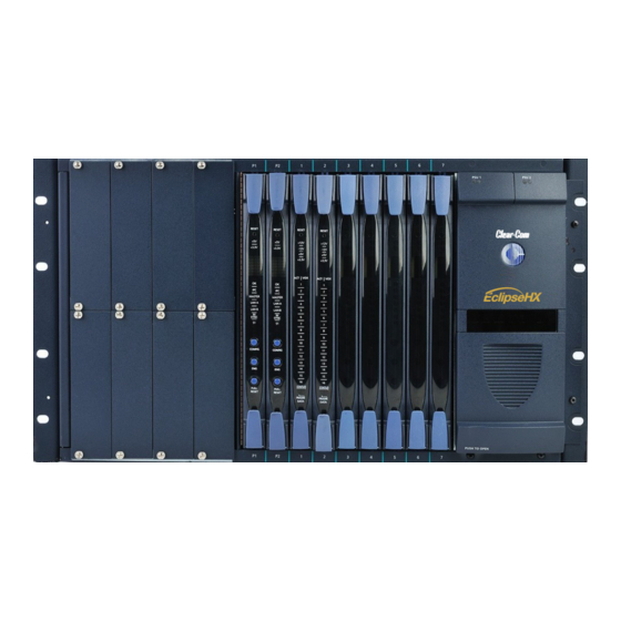
3.2 Eclipse HX-Median A complete Eclipse HX-Median system consists of a central matrix and the remote audio devices (which may include user panels, interface cards, interface modules, four-wire devices and systems) connected to it. Note: The term central matrix is used to differentiate the core hardware and software from the connected user panels and interfaces. - Page 16 Figure 2: Eclipse HX-Median front panel Eclipse HX-Median User Guide...
- Page 17 Key: Eclipse HX-Median front panel Feature Description Interface module slots (unused in this example). The Eclipse HX-Median can house up to 8 interface modules. Blank panels can be installed to unused slots. For more information about interface modules, see 3.5 Interface modules CPU cards (P1 and P2).
- Page 18 Figure 3: Eclipse HX-Median rear panel Eclipse HX-Median User Guide...
- Page 19 Key to Figure 3: Eclipse HX-Median rear panel Feature Description IEC power supply connectors. For more information about the twin power supplies, see 3.2.2 Power supplies Spare slots for interface card rear connector panels. All front installed interface cards require a corresponding rear connector panel. Blank panels can be installed to unused slots.
-
Page 20: Power Supplies
3.2.2 Power supplies The Eclipse HX-Median matrix has two Euro Cassette power supply units that can be easily installed or removed as needed. One power supply unit can power an entire matrix. The second unit provides a backup in case of failure or damage to the first unit. In addition, the two supplies have separate IEC connectors to AC mains, and are designed for completely automatic and transparent changeover between supplies in the event of a power outage in one of the AC mains circuits. -
Page 21: Cpu Card
• Matrices that link across cities, nations, or continents through trunk lines. • Uses the same fiber-networking interface as the Eclipse HX-Omega matrix. • Connection to FreeSpeak/CellCom antennas and splitters using the E-QUE interface card. • Connection to IP enabled V-Series panels and Concert users over IP networks using the IVC-32 interface card. -
Page 22: Interface Cards
3.3 Interface cards You can fit 7 interface cards to the Eclipse HX-Median. The number of different types of interface card you can fit to the matrix frame is limited by the available port count (112 audio ports). For more information, see 4.4.3 Combining interface cards in the frame. -
Page 23: E-Que E1/T1 Interface Card
3.3.3 E-QUE E1/T1 interface card The E-QUE E1/T1 interface allows the Eclipse HX-Median to connect to FreeSpeak/CellCom antennas, FreeSpeak/CellCom antenna splitters, and E1 and T1 trunk lines. Each E-QUE interface card set comprises: • A front card with a reset button and various status indicators. •... -
Page 24: Ip Interface Card
Each IVC-32 front card has status LEDs for power, port activity and LAN status. The LAN indicators show whether there is a LAN connection and the IP activity on the LAN port. Clear-Com recommends fitting IVC-32 cards in the leftmost available slots (with the MVX-A16 cards) Eclipse HX-Median. on the... -
Page 25: Interface Modules
3.4 Interface modules Interface modules convert the four-wire signals of a central matrix port to other types of signals that communicate with devices such as telephones, camera intercoms, two-way radios, and so on. In this way non-four-wire devices can communicate with the central matrix. -
Page 26: User Panels
The EHX system can be set up to run on a client/server model over a network, allowing the system administrator to control multiple matrices remotely. 3.6 User panels The following Clear-Com user panels are compatible with the Eclipse HX-Median: • V-Series panels, including expansion panels. -
Page 27: Installing The Eclipse Hx-Median
See 12.24 and 12.25 Minimum PC requirements (for EHX software) Recommended PC respectively. requirements (for EHX software) • CAT5 cables (to connect the matrix to user panels, interface modules, and other devices). Clear-Com recommends shielded cables. Eclipse HX-Median User Guide... -
Page 28: Reconnecting The Cpu Card Backup Battery
4.1.3 Reconnecting the CPU card backup battery Important: Before the Eclipse HX-Median is installed, the CPU card’s backup battery must be reconnected. The matrix will operate if the battery is not reconnected. However, if the matrix is powered down, all run time information (dynamic assignments, crosspoint states and levels) will be lost. - Page 29 Eclipse HX-Median CPU cards are fitted with a socketed battery, normally a Renata CR2477N with a capacity of 950mAh and a life of approximately 247 days. These socketed batteries are easily replaced and this operation does not have to be carried out by service personnel.
-
Page 30: Installing The Eclipse Hx-Median
Danger of explosion if battery is incorrectly replaced. Replace only with the same or equivalent type. Lithium batteries can overheat or explode if they are shorted. When handling the CPU card or a loose battery, do not touch any external electrical conductors to the battery’s terminals or circuits to which the terminals are connected. -
Page 31: Installing The Power Supplies
The matrix will continue to operate even if one of the AC power branches fails. Clear-Com supplies each matrix with power supplies already installed. When the matrix is installed connect the power supplies to AC mains power using the IEC power connectors on the matrix’s rear panel. -
Page 32: Installing Cpu Cards
4.3 Installing CPU cards The CPU card’s components include CMOS chips which are sensitive to static electricity. Before touching the CPU card touch a grounded metal object, such as any unpainted surface on the matrix, to dissipate static electricity. While handling the CPU card, be careful not to bend any of the card’s connector pins or component leads. -
Page 33: Hot Patching Cpu Cards
To insert a CPU card in the matrix: 1. Carefully place the card in the appropriate slot. Make sure the card is aligned with the top and bottom precision guides. 2. When the card has almost reached the backplane connectors, open the two ejectors, allowing them to clear the edges of the matrix. -
Page 34: Checking The Cpu Card Installation
4.3.2 Checking the CPU Card installation The following lights indicate that the card has been properly installed in the matrix: RESET The two power supplies are lit green to indicate that they are working. +3.3V IPC (Interprocessor Dot matrix display indicates communication) LED is lit which of the four stored green to indicate that the two... -
Page 35: Installing Interface Cards
4.4 Installing interface cards 4.4.1 Installing an interface card to the matrix frame Note: Before installing an interface card, ensure that the card’s associated rear-connector panel has already been installed. To install an interface card: 1. Carefully place the card in the appropriate slot. Ensure that the card is aligned with the top and bottom precision guides. - Page 36 E-QUE cards have 60 ports in E1 mode or 48 ports in T1 mode. Recommendation Clear-Com recommends fitting E-FIB cards on the right of the matrix frame, and fitting MVX-A16, IVC-32, E-MADI64, E-QUE E1/T1 direct cards on the left of the frame, where possible.
-
Page 37: Static Sensitivity
4.4.4 Static sensitivity Observe anti-static procedures. Devices can be damaged by static electricity. Personnel reconnecting the battery should ensure that they ground themselves and all tools before touching cards. A CPU / interface card’s components include CMOS chips that are sensitive to static electricity. -
Page 38: Configuration
4.4.7 Configuration When an interface card is physically installed, its ports must be assigned functions in the EHX configuration software (see your EHX documentation). 4.4.8 Checking MVX-A16 analog port card installation The following front panel lights indicate that an analog port card has been properly installed in the matrix: RESET One of the four power-supply lights... -
Page 39: Wiring Audio Devices To The Matrix Frame
The EHX configuration software allows the changing of the audio input reference level between -12, - 9, -6, -3, 0, +3, +6, +9, +11 dB. Figure 9: Direct matrix frame port connection Clear-Com recommends the use of shielded cable. Tip: The Eclipse HX Installation Guide gives complete details about wiring audio devices to the matrix. -
Page 40: Wiring Panels To The Matrix Frame
4.6 Wiring panels to the matrix frame Eclipse HX uses a 4-pair (analog) or single-pair (digital) wiring scheme between the matrix and panels. All Eclipse HX user panels (V-Series and I-Series panels) have built-in RJ-45 connectors. 4.6.1 4-Pair analog Four-pair analog wiring is performed with shielded CAT5 RJ-45 cable: Pair Description Pair 1... -
Page 41: Single-Pair Digital
4.6.2 Single-pair digital Single-pair digital wiring is accomplished with double-shielded 24 AWG conductor CAT-6E enhanced STP cable. Pair 1 transmits and receives multiplexed digital and analog between the matrix and the panel. Ensure that the Select switch on the rear of the panel is in the correct position for the intended use. -
Page 42: Wiring Cpu Card Interfaces
4.7 Wiring CPU card interfaces The CPU card holds the circuitry for connecting to, and communicating with, the following interfaces: • An external personal computer. • Alarm inputs and outputs. • Eight general purpose inputs (GPIs). • Eight general purpose outputs (GPOs or relays). •... -
Page 43: Cpu Card Interface Connectors
4.7.1 CPU card interface connectors GPI/ RLY INTERFACE RS-232 ALARM I/O GP-OUT GP-IN LAN1 LAN2 Figure 12: CPU card interface connectors Eclipse HX-Median User Guide... - Page 44 If this port is used a ferrite core must be added to the socket end of each cable. A suitable ferrite core is Würth Electronik part: 74271132. Clear-Com recommends the use of shielded cable. For wiring pinout information for GPI/RLY interfaces, see: •...
- Page 45 Matrix Frame Computer Serial Port DB-9F "IBM-PC RS-232" Cable Connector DB-9M Cable Connector Receive (RXD) Transmit (TXD) Transmit (TXD) Receive (RXD) Ground (GND) Figure 13: Wiring the matrix DB-9M to the PC DB-9F Matrix Frame Computer Serial Port DB- "IBM-PC RS-232" 25F Cable Connector DB-9M Cable Connector...
- Page 46 Alarm I/O Connector The DB-9F connector labeled Alarm I/O connects the matrix to a control circuit for an external alarm, such as a light or bell. The external alarm activates whenever an alarm condition is detected in the matrix. The following conditions trigger an alarm: •...
- Page 47 Figure 16: Double-pole double-throw alarm relay General-Purpose Outputs Connector (GP OUT) A GPO can be programmed to mute a speaker, to turn on an applause light, to turn on a door lock, or to perform a variety of other functions. For example, to get the attention of a panel operator working in a high-noise environment such as a control booth, a relay can be programmed to switch on a light at the operator panel each time an incoming call is received, to...
- Page 48 Figure 17: Pin configuration of the GPO connector General-Purpose Inputs Connector (GP IN) The DB-25 connector labeled GP IN connects the matrix to eight local general-purpose inputs (GPIs). An external device such as a foot switch, a panel-mounted switch or the logic output of some other device can be connected to the GP IN connector.
- Page 49 To select a mode, move the J1 jumper on the CPU rear card to one of two positions. The J1 jumper is located on the inner-matrix side of the DB-25 connector. For opto-isolated mode, fit the J1 jumper across pins 1 and 2. For non-isolated mode, fit the J1 jumper across pins 2 and 3.
- Page 50 Figure 19: Non-isolated mode Figure 20: Pin configuration of the General Inputs connector Local Area Network connector (LAN1) The LAN1 and LAN2 connectors have standard Ethernet pin assignments. below for pin assignments. The RJ-45 socket labeled LAN 1 connects a local area network (LAN) to the CPU card through a standard Ethernet connection.
- Page 51 If this port is used a ferrite core must be added to the socket end of each cable. A suitable ferrite core is Würth Electronik part: 74271132. Clear-Com recommends the use of shielded cable. Local Area Network connector (LAN2) The LAN1 and LAN2 connectors have standard Ethernet pin assignments.
-
Page 52: Dse1/T1 Matrix To Matrix Crossover Cable Connections
4.8 DSE1/T1 Matrix to Matrix crossover cable connections For E1 and T1 direct matrix to matrix connections the CAT5 crossover cables should be wired, as shown in the table below: Matrix 1 Pin Description Matrix 2 Pin Not connected Not connected Not connected Not connected Table 8: E1/T1 Crossover cable... -
Page 53: E1 To Freespeak / Cellcom Antenna Straight Cable Connection
4.10 E1 to FreeSpeak / CellCom antenna straight cable connection Straight CAT5 cables are used to connect an E-QUE card to a FreeSpeak / CellCom antenna or splitter. The E1 pinout for connecting an antenna or splitter is shown in Table 11: E1 pinout for connecting a FreeSpeak / CellCom antenna or splitter Cable wiring is shown in Table 12: E1 to FreeSpeak / CellCom antenna or splitter straight... -
Page 54: Using The Eclipse Hx-Median
5 Using the Eclipse HX-Median This chapter describes how to operate the Eclipse HX-Median matrix frame, including its CPU cards and interface cards. Tip: For an overview of the Eclipse HX-Median, see 3 Overview 5.1 Creating and storing system configurations A configuration is a complete set of operating parameters for the system which includes talk and listen paths for each connected intercom device. -
Page 55: Setting The Default Ip Address
5.2 Setting the default IP Address To reset the CPU LAN ports to their default IP addresses, press and hold the ENG and FULL RESET buttons on the CPU front card until the card resets. Note: Do not release the ENG and FULL RESET buttons until the CPU card LED panel shows either an A or a B The LAN1 Ethernet port is reset to the factory default address of and the... -
Page 56: Configuration Restrictions For Ethernet Ports
5.3.1 Configuration restrictions for Ethernet ports The network ID on the first Ethernet port must be different to that of the second port. The network ID is defined by the IP address and the network mask for the port. For example a network address of and a mask of gives a network ID of... -
Page 57: Cpu Card Lights And Controls
5.5 CPU card lights and controls RESET +3.3V MASTER LAN A LAN B IN SYNC CONFIG RESET Figure 22: CPU card lights and controls Eclipse HX-Median User Guide... - Page 58 Key to CPU card lights and controls Feature Description RESET button Pressing the RESET button causes the CPU card to stop its current activity and to restart. The same configuration that was active before the system was reset will be active after the system was reset. During the reset, configuration information reloads to the card’s operational memory from its non-volatile memory and the card starts running again from the beginning.
- Page 59 Note: The dot matrix lights will also display system information when the ENG button is pressed on the master CPU card. This is described below in the section on the ENG button. Status lights OK Light When flashing, the OK light indicates that the CPU card is successfully communicating with the EHX configuration software.
- Page 60 Configuration [ CONFIG ] button The CPU card can hold four complete system configurations in its operational memory. When the CONFIG button is pressed the number of the currently active configuration (either 1, 2, 3, or 4) appears in the dot-matrix display. Each time the button is subsequently pressed the next configuration number in the series appears in the dot-matrix display.
-
Page 61: Using The Embedded Configuration
software (for example, RACK 1.0.2.1). • Hardware serial number. For example, SERIAL 2251, in the case where the HW serial number is 2251. Full Reset button When a full reset is performed, all cards in the matrix reset, regardless of any system preferences in the program software. - Page 62 To activate the embedded configuration: 1. On the front of the CPU card, press and hold the CONFIG and the ENG buttons. 2. Simultaneously, reset the CPU card by pressing and holding the CPU card’s lower RESET button (the Full reset button). Note: A tool, such as a pin, is used to press and hold the RESET button.
-
Page 63: Mvx-A16 Analog Card Front-Panel Lights And Controls
5.6 MVX-A16 analog card front-panel lights and controls RESET +12V -12V +3.3V ACTIVE VOX FRAME STATUS DATA Figure 23: MVX-A16 analog card front panel lights and controls Eclipse HX-Median User Guide... - Page 64 Key to MVX-A16 analog card lights and controls Feature Description RESET button Pressing the RESET button causes the card and all connected audio devices to momentarily stop their current activity and to restart. The card’s “frame data” light goes off when the reset starts and comes back on when the reset is complete.
-
Page 65: Diagnosing Power Supply Problems
VOX Lights When lit a VOX light indicates that the audio level on a connected device, such as an intercom panel or interface, has exceeded a preset threshold. The threshold audio level is set through the EHX application. Each of the port card’s 16 green VOX lights corresponds to one of 16 rear- panel connectors or “ports”... - Page 66 Euro Cassette Euro Cassette Power Supply 1 Power Supply 2 Euro Cassette Alarm lights Power supply lights (green when lit): Alarm lights +12 V light (red when lit): +5 V light +3.3 V light Main alarm light -12 V light External alarm light Temp alarm light Fan-fail alarm light...
-
Page 67: Conditions That Cause An Alarm
5.7.1 Conditions that cause an alarm The following conditions trigger an alarm: • If any of the voltages produced by the first power supply unit fall below normal levels. • If any of the voltages produced by the second power supply unit fall below normal levels. -
Page 68: Alarm Reset Button
5.7.3 Alarm reset button When the alarm reset button is pressed the following events take place, even if the alarm condition has not been corrected: • The internal audible alarm buzzer stops buzzing. • Any wired relay contacts return to their inactive state. If these relays are connected to external alarm lights or alarm buzzers, those lights or buzzers shut off. -
Page 69: Power Supply Lights
PSU1 Fail When the first power supply unit is operating correctly, the PSU1 light stays off, while the four green power supply lights (+12V, +5V, +3.3V, -12V) stay on continuously. If a DC output or AC input to the first power supply drops too low, the PSU1 light switches on. -
Page 70: Connecting The Matrix Frame
5.8 Connecting the matrix frame Tip: For detailed information about connecting the matrix to panels, interfaces and other devices, see 4 Installing the HX-Median The Eclipse HX-Median matrix frame connects to devices such as the external computer that runs the EHX configuration software, panels, interfaces, and other matrices through its rear- panel hardware connectors, often called ports. -
Page 71: Connecting The Cpu Card
IVC-32 card An IVC-32 card provides a RJ-45 port for connection to an IP network. No other ports are used. LMC-64 card An LMC-64 card provides a RJ-45 port for connection to an IP network. No other ports are used. Table 14: Rear connector panels Note: A blank panel covers an unused slot in the matrix. - Page 72 Each rear connector panel associated with an E-QUE interface holds eleven RJ-45 ports: • Eight ports for connection to wireless equipment. • Two ports for DECT sync. • One port for LAN connections. Each rear connector panel associated with an IVC-32 interface holds eleven RJ-45 ports: •...
- Page 73 6 E-MADI64 card This chapter describes the E-MADI64 card. The E-MADI64 is a MADI (Multichannel Audio Digital Interface) card, providing up to 64 duplex channels of AES3 digital audio over a coaxial cable or fiber pair between compatible devices. he card supports both direct and trunk connections. You can limit the quantity of channels to 32, 56 or 64 channels in EHX.
- Page 74 6.1 E-MADI64 front panel lights and controls RESET +3.3V LOCK VID WRD 44.1 CHANNELS ERROR ACTIVE E-MADI Figure 25: E-MADI64 front panel lights and controls Eclipse HX-Median User Guide...
- Page 75 Important note: Figure 25 shows an unconfigured E-MADI64 card , when all lights are lit to indicate their location. On a card with a clock source and MADI connections ( where the received MADI signal matches the card set up), the following lights are lit: the Lock source LED [ ], the Sample rate (Fs) LED ], the Channels LED [ ] and the Active LED [...
- Page 76 Sample rate or Sf (Sampling frequency) green LED indicates the current sampling rate of the MADI channels. The sample rate is determined in EHX when a video sync is used, or automatically detected from the clock source when a Word clock is used. Note: If the quantity of channels is 32, the sampling rate is either 44.1KHz, 48KHz or 96KHz.If the quantity of channels is either 56 or 64, the sample rate is either...
- Page 77 6.2 E-MADI64 rear panel connectors E-MADI MADI MADI IN MADI OUT CLOCK Figure 26: E-MADI64 rear panel connectors Eclipse HX-Median User Guide...
- Page 78 Warning: Eye Safety This LED based single mode transceiver is a Class 1 LED product. It complies with IEC 60825-1/A2:2001 and FDA performance standards for laser products (21 CFR 1040.10 and 1040.11) except for deviations pursuant to Laser Notice 50, dated July 26, 2001. Normally a protective plug is fitted to the fiber connector to protect the connector from damage or the entry of foreign materials.
- Page 79 6.3.1 MADI channel labeling The 4-character channel ID for each MADI input channel is taken from the provided embedded data bits. The channel ID for each MADI output channel can be re-labeled in EHX, or alternatively replaced with Production Maestro Pro alias labels. This means that Eclipse HX user panels can automatically show the MADI channel ID (or Alias as supplied from Production Maestro Pro).
- Page 80 4. Configure EHX settings for the E-MADI64 cards. Standard EHX settings (including VOX and In-use tally) are applicable to all E-MADI64 channels. Note: Card Properties permits sample rate selection when synching to video signals. It is only used when not using the Word Clock Source Sync (see below). Card Properties always defaults to the E-MADI64 standard for the number of channels: E-MADI64 channel mode Sample rate...
- Page 81 6.4.3 Connecting E-MADI64 Audio (using Coaxial or Fiber cable) When you connect the external E-MADI64 Audio (using Coaxial or Fiber cable) to the rear of the E-MADI64 card: 1. The sample rate and the number of configured ports is indicated by a solid green LED on the front of the E-MADI64 card.
-
Page 82: Overview
7 E-FIB fiber card This chapter describes how to connect Eclipse HX matrix frame using E-FIB fiber interface cards. E-FIB fiber interface cards connect Eclipse HX matrices together to provide a high speed, dual redundant link to transfer audio samples and data between systems. These connections can be configured in various ways to provide protection against the loss of a link or a node. - Page 83 7.1 E-FIB front panel lights and controls RESET +3.3V PROC FRONT REAR TXVRA ACT LINK ERR TXVR TXVRB ACT LINK ERR TXVR STATUS FRAME DATA Figure 27: E-FIB front panel lights and controls Eclipse HX-Median User Guide...
- Page 84 Key to E-FIB front panel lights and controls Feature Description RESET button Pressing the RESET button causes the card and all links to momentarily stop their current activity and to restart. The card’s frame data light goes off when the reset starts and comes back on when the reset is complete. During the reset, configuration information downloads to the card and its connected matrices from the CPU card.
- Page 85 Secondary Link Status LEDs These LEDs indicate the status and functioning of the secondary (B) fiber optic link. Link LED This LED indicates whether a link has been established on the secondary fiber optic circuit (transceiver B). When illuminated a link is present. TXVR LED This LED indicates when data is being transmitted on the secondary circuit.
- Page 86 7.2 E-FIB rear panel lights and connectors +3.3V TXVRB Transceiver lasers TXVRA Figure 28: E-FIB rear panel lights and connectors Warning: Eye Safety This laser based single mode transceiver is a Class 1 Laser product. It complies with IEC 60825-1/A2:2001 and FDA performance standards for laser products (21 CFR 1040.10 and 1040.11) except for deviations pursuant to Laser Notice 50, dated July 26, 2001.
- Page 87 Important note: Primary and secondary fiber ports are reversed with respect to the front panel indicators. Care should be taken when connecting or disconnecting cables to ensure that they are connected correctly and not reversed. Key to E-FIB rear panel connectors Feature Description +3.3-Volt Power Supply LED...
- Page 88 System 1 System 2 Primary ring Redundant ring TXVRB TXVRB TXVRA TXVRA System 3 TXVRB TXVRA Figure 29: Primary and redundant ring configuration 7.3 Configuring a fiber optic connection There are a number of ways that optical connections can be made between systems depending on the level of redundancy required.
- Page 89 7.4 Simplex fiber cabling 7.4.1 Single card set redundancy In this scenario, each matrix contains one fiber-optic Linking card set (see Figure 30: Ring topology: single card set redundancy This approach still affords fiber connection redundancy since each rear card houses two fiber-optic transceivers.
- Page 90 Loss of single fiber connection If a single fiber connection is lost on one ring and the other ring is intact then the active ring always attempts to heal itself by reversing the direction of data flow to bypass the failed connection.
- Page 91 7.4.2 Dual card set redundancy Dual card set redundancy is shown in Figure 27: Ring topology; Dual card set redundancy with both Card set A and Card set B fitted in each node of the ring. In this case each matrix contains two Fiber-optic Linking card sets.
- Page 92 Loss of single fiber connection If a single fiber connection is lost on one ring and the other ring is intact then the active ring always attempts to heal itself by reversing the direction of data flow to bypass the failed connection.
- Page 93 The configuration software will report the failure correctly as two failed cables. If two non- adjacent fiber connections are lost on one ring and the other ring has a similar fault the nodes adjacent to the failures will loop-back their connections to the failed cables healing the ring into 2 separate smaller rings.
- Page 94 If a Matrix frame, connected as a node of the fiber-optic link is reset, powered down or failed this will constitute a lost or failed node on both rings and this node will experience audio breaks or disturbances and loss of crosspoint information or data for up to 5 seconds after the fault condition is cleared or repaired.
- Page 95 System #1 System #2 System #3 TX2- E-FIB TX2- E-FIB TX2- E-FIB card#1 - RX2 card#1 - RX2 card#1 - RX2 TX1- E-FIB TX1- E-FIB TX1- E-FIB card#1 - RX1 card#1 - RX1 card#1 - RX1 System #5 System #4 TX1- E-FIB TX1- E-FIB card#1 - RX1...
-
Page 96: Que E1/T1 Card
8 E-QUE E1/T1 card The E-QUE interface card allows you to connect the Eclipse matrix to FreeSpeak/CellCom antennas and FreeSpeak/CellCom antenna splitters, E1 and T1 trunk lines and E1 direct lines. The E-QUE interface cards must be fitted in the rightmost available slots on the HX-Omega (furthest from the CPU cards). - Page 97 8.1 E-QUE front panel lights and controls RESET +3.3V STATUS LAN DATA LINK Figure 33: E-QUE front panel lights and controls Eclipse HX-Median User Guide...
- Page 98 Key to E-QUE front panel lights and controls Feature Description RESET button Pressing the reset button causes the card and all links to momentarily stop their current activity and to restart. During the reset, configuration information downloads to the card from the CPU card.
- Page 99 8.2 E-QUE rear panel connectors Ref in DECT Ref out E-QUE 1 – 4 5 – 8 Figure 34: E-QUE rear panel connectors Eclipse HX-Median User Guide...
- Page 100 Key to E-QUE rear panel connectors Feature Description LAN port (RJ-45) The LAN port is used for diagnostic purposes. DECT sync ports: DECT Ref in DECT Ref out E1 / T1 Port 1 - 4(RJ-45) E1 / T1 Port 5 - 8 (RJ-45) Table 21: Key to E-QUE rear panel connectors When multiple E-QUE cards are fitted in a rack, one of the cards generates a clock signal, which all other cards lock to, to ensure that all antennas remain in sync.
- Page 101 8.3 E-QUE interface card applications The E-QUE interface card may be used to connect: • FreeSpeak/CellCom antennas and splitters to an Eclipse HX matrix . • Provide E1 and T1 connections to other systems. Tip: For more information about E1 and T1 cable pinouts and cable connections, see: •...
- Page 102 Figure 35: E-QUE card antenna connection Figure 36: E-QUE card splitter connection Eclipse HX-Median User Guide...
- Page 103 Each antenna can handle up to five beltpacks simultaneously and switch service between antennas under control of the matrix as the beltpack user moves around the site. The DC In power connector is used to locally power the transceiver/antenna with the supplied universal power supply.
- Page 104 Note: All connections are made using CAT5 cable and it is recommended that shielded cable is used. If an E-QUE interface is fitted in the matrix with antennae or splitters connected and active inserting a second E-QUE interface to the left of the first interface (seen from the front) will cause a temporary loss of audio to beltpacks using the original E-QUE interface (usually for about 10 seconds).
- Page 105 Figure 38: Matrix to Matrix direct E1 Trunking E1 trunking between matrices can also be achieved over an E1 network, as shown Figure 38: E1 Trunking with an E1 Network In this case E1 ports 1 and 5 of the E-QUE interface are connected using standard straight- through CAT5 cables rather than crossover CAT5 cables.
- Page 106 Figure 39: E1 Trunking with an E1 Network The E-QUE interface can also be used to connect the matrix to third party equipment using E1 port 1 or 5. Figure 40: Matrix to Third Party E1 connection Eclipse HX-Median User Guide...
- Page 107 The CAT5 cable connecting the E1 port on the E-QUE rear card may be a crossover cable or a straight-through cable depending on the requirements of the third party equipment. The E-QUE interface should be set to Direct in EHX. 8.5 T1 trunking The E-QUE interface card can provide T1 trunking between Eclipse systems and between Eclipse systems and compatible third-party equipment.
- Page 108 Figure 41: Matrix to Matrix T1 Trunking T1 trunking between matrices can also be achieved over a E1 network as shown in Figure 40: T1 Trunking using a E1 Network In this case T1 ports 1 and 5 of the E-QUE rear card are connected using standard straight- through CAT5 cables rather than crossover CAT5 cables.
- Page 109 Figure 42: T1 Trunking using a E1 Network 8.6 Trunking failover Where the E1/T1 trunking has been configured with redundant trunks audio will be switched from the primary trunk to the backup trunk when a failure is detected. When failover occurs from primary to backup there will be a three second audio break on any route running over the trunk.
-
Page 110: Card For Ip-Based Connections
9 IVC-32 card for IP-based connections The IVC-32 (Instant Voice Communication) interface card provides the Eclipse HX- Median with connectivity over IP to V-Series IP panels and Concert servers. Each IVC-32 interface card comprises: • A front card with a reset button and various status indicators (including status LEDs for power, port activity and LAN status). - Page 111 9.1 IVC-32 front panel lights and controls RESET +3.3V STATUS LAN DATA LINK Figure 43: IVC-32 front panel lights and controls Eclipse HX-Median User Guide...
- Page 112 Key to Figure 41: IVC-32 front panel lights and controls Feature Description RESET button Pressing the reset button causes the card and all links to momentarily stop their current activity and to restart. During the reset, configuration information downloads to the card from the CPU card.
- Page 113 9.2 IVC-32 rear panel connectors Ref in DECT Ref out IVC-32 1 – 4 5 – 8 Figure 44: IVC-32 rear panel connectors Eclipse HX-Median User Guide...
- Page 114 Key to IVC-32 rear panel connectors Feature Description LAN port (RJ-45) DECT sync ports: DECT Ref in (Not used) DECT Ref out (Not used) E1 / T1 Port 1 - 4 (Not used) E1 / T1 Port 5 - 8 (Not used) Table 23: Key to IVC-32 rear panel connectors Note: The E1/T1 and DECT ports are not used on the IVC-32 interface and should not be...
- Page 115 Links have to be made over IP before the trunk/direct can be used. 9.3.3 Concert Users The IVC-32 interface will allow Concert users to establish audio links with users on the Eclipse matrix via the Concert IV-R server. This server will provide a link over IP between Concert users and the Eclipse matrix. Concert users cannot connect directly to the IVC-32 interface card.
-
Page 116: Metering Card
LMC-64 metering card The Level Meter Card (LMC-64) interface card enables the Eclipse HX-Median to provide audio level metering for Production Maestro Pro over a network. Each LMC-64 interface card can meter up to 64 virtual partylines (conferences) and four-wire ports. - Page 117 10.1 LMC-64 front panel lights and controls RESET +3.3V STATUS LAN DATA LINK Figure 46: LMC-64 front panel lights and controls Eclipse HX-Median User Guide...
- Page 118 Key to IVC-32 front panel lights and controls Feature Description RESET button Pressing the reset button causes the card and all links to momentarily stop their current activity and to restart. During the reset, configuration information downloads to the card from the CPU card.
- Page 119 10.2 LMC-64 rear panel connectors Ref in DECT Ref out LMC-64 1 – 4 5 – 8 Figure 47: LMC-64 rear panel connectors Eclipse HX-Median User Guide...
- Page 120 Key to LMC-64 rear panel connectors Feature Description LAN port (RJ-45) DECT sync ports: DECT Ref in (Not used) DECT Ref out (Not used) E1 / T1 Port 1 - 4 (Not used) E1 / T1 Port 5 - 8(Not used) Table 25: Key to LMC-64 rear panel connectors Note: The E1/T1 and DECT ports are not used on the IVC-32 interface and should not be...
- Page 121 10.3 LMC-64 interface applications The LMC-64 interface broadcasts audio level data to Production Maestro Pro clients over an IP network. This enables multiple Production Maestro Pro clients across a network to display any audio level that is being metered. Figure 48: Audio level metering with the LMC-64 interface Eclipse HX-Median User Guide...
-
Page 122: Maintaining The Eclipse Hx-Median
Maintaining the Eclipse HX-Median The Eclipse HX-Median matrix system connects a complex network of microprocessor controlled devices. Due to the complexity of the system, field service should be limited to isolating a problem to the specific circuit board that may be causing the problem. Once the circuit board has been identified, it can be either repaired or replaced. - Page 123 11.1.2 Spare parts To facilitate quick repair of the system with minimum downtime, Clear-Com recommends keeping the following spare system components in good working condition at all times: • One CPU card. • One CPU interface card. • One Euro Cassette power supply module of the type fitted to the matrix.
- Page 124 Backplane connector malfunctions are rare, but should be considered as possibilities. Note: Clear-Com may ship a spare matrix to use while the damaged matrix is being repaired depending on the support status. For more information, see your warranty and support documentation.
- Page 125 If the power supply lights illuminate, the problem may be in the matrix’s backplane connectors, which carry electric current from the power supplies to the cards. The matrix can be returned to Clear-Com for investigation or repair. In the meantime another matrix can be substituted for the damaged one.
- Page 126 Clear-Com for investigation or repair. In the meantime another matrix can be substituted for the damaged one. Note: Clear-Com may ship a spare matrix to use while the damaged matrix is being repaired depending on the support status. For more information, see your warranty and support documentation.
- Page 127 If the problem persists even after the power supply has been replaced, the problem is in the backplane. Send the matrix back to Clear-Com for repair or replacement. In the meantime another matrix can be substituted for the damaged one.
- Page 128 CPU card Reset button When the CPU card is reset by pressing its reset button, the card’s non-volatile memory reloads all configuration information to the card’s microprocessor. Resetting the card clears any corruption of data in the card’s microprocessor. The card momentarily stops its current activity and restarts.
- Page 129 Problem: Audio sounds low or distorted from a panel. Action 1: Check the matrix’s currently active CPU card’s power lights. If any of the lights are not lit, replace the card. Action 2: Check the analog port input and output gain settings for the port in EHX. Action 3: Check the panel’s listen-level adjustment settings in EHX.
-
Page 130: Specifications
Specifications Note: 0 dBu is referenced to 0.775 volts RMS. 12.1 Matrix frame capabilities Category Number / Comments Maximum Expansion Cards Ports per MVX Port Card Maximum MVX Port Cards Maximum CPU Cards 2 (included) Maximum Fibre Expansion Cards Maximum E-Que or IVC-32 or 4 (in total) LMC-64 Expansion Cards Maximum Power Supply Units... - Page 131 12.3 Environmental Category Measures / comments Operating Temperature 0º C to +40º C, ambient Storage Temperature -55º C to +70º C Humidity, Maximum 90% non-condensing Table 28: Environmental 12.4 Matrix frame performance Category Measures / Comments Sample Rate 48 kHz Resolution 24 bit Frequency Response...
- Page 132 12.6 E-MADI64 interface rear card Category Measures / comments Height Depth 58mm (max) Operating Temperature 0º C to +40º C Storage Temperature -55º C to +70º C Humidity 40 - 90% non-condensing Power +3.3V Table 31: E-MADI64 interface rear card 12.7 E-MADI64 fiber cable Category Measures / comments...
- Page 133 12.9 E-MADI64 clock sources Clock type Clock source Word Clock 44.1KHz 48KHz 96KHz NTSC SD Video 720P60 HD Tri-Level Sync 720P59.94 720P50 720P30 720P27.97 720P25 720P24 720P23.98 1080P60 1080P59.94 1080P50 1080P30 1080P29.97 1080P25 1080P24 1080P23.98 1080I30 1080I29.97 1080I25 1080I24 1080I23.98 Table 34: E-MADI64 clock sources 12.10 Fiber interface front card...
- Page 134 12.11 Fiber interface rear card Category Measures / comments Height Depth 58mm (max) Operating Temperature 0º C to +40º C Storage Temperature -55º C to +70º C Humidity 40 - 90% non-condensing Power +3.3V Table 36: Fiber interface rear card 12.12 Fiber cable Category...
- Page 135 12.14 E-QUE interface front card Category Measures / comments Height Depth 300 mm Operating Temperature 0º C to +40º C Storage Temperature -55º C to +70º C Humidity 40 - 90% non-condensing Power (combined cards) +3.3V 3.5A +5V 0.7A +12V 0.05A Table 39: E-QUE interface front card 12.15 E-QUE interface rear card...
- Page 136 12.17 IVC-32 interface rear card Category Measures / comments Height Depth 58 mm (max) Operating Temperature 0º C to +40º C Storage Temperature -55º C to +70º C Humidity 40 - 90% non-condensing Table 42: IVC-32 interface rear card 12.18 LMC-64 interface front card Category Measures / comments...
- Page 137 12.20 Analog port card (MVX-A16) Category Measures / comments Height 6 RU Depth 300 mm Audio Interface 16, bi-directional Input Format Balanced Output Format Balanced None; expected at User Panel/Station Ground Isolation Analog port card outputs Level 0 dBu nominal Impedance 100 Ohms balanced Frequency Response...
- Page 138 12.22 Backplane connector: FCI/BERG Metral Category Measures / comments Port Connector RJ-45 to Clear-Com standard pinout Transmission Distance 3000 ft. (1000 m) maximum Table 47: Data interface: 16 bi-directional 12.23 System programming Category Measures / comments Group Calls Number of Grouped Ports...
- Page 139 12.24 Minimum PC requirements (for EHX software) Specification Description / Value Processor 1 GHz Memory 1GB RAM Hard disk 32 bit: 1GB minimum 64 bit: 2GB minimum 64 bit Input devices CD-ROM drive Display resolution SVGA User entry Keyboard, Mouse Ports 2 serial ports and/or network IEEE 802.3 Ethernet card Network...
- Page 140 12.25 Recommended PC requirements (for EHX software) Specification Description / Value 2GHz or greater for a client. Processor As many cores as possible for a server. Memory 32 bit: 2GB for client 3GB for server 64 bit: 4GB for client 4GB+ for server Free space 32 bit:...
- Page 141 Table 51: Power supply unit Notice about specifications While Clear-Com makes every attempt to maintain the accuracy of the information contained in its product manuals, this information is subject to change without notice. Performance specifications included in this user guide are design-center specifications and are included for customer guidance only and to facilitate system installation.
-
Page 142: Glossary
Glossary Term Definition Any of the Eclipse HX matrix’s analog input/output RJ-45 Analog Port connectors that are used to connect cable from the matrix to panels and interfaces. Each port connects to a separate audio channel in the matrix. Alias label A label that is temporarily assigned and replaces a previously labeled port or conference. - Page 143 Conference An internal matrix virtual partyline or busbar where many panels and interfaces can talk onto or listen from the partyline without talking to themselves. Destination A device such as an intercom panel, beltpack, or interface to which audio signals are sent. The device from which audio signals are sent is called a source.
- Page 144 The ISO function, short for panel ISOlation, allows a panel operator to call a destination and interrupt all of that destination’s other audio paths and establish a private conversation. When the call is completed the destination’s audio pathways are restored to their original state before the interruption.
- Page 145 Remote panel Any intelligent intercom device connected to the back-panel ports of the matrix frame . This term does not refer to devices connected through interfaces. Sidetone The sound of the panel operator’s voice, as heard in their own earphone(s) as they speak. Source In this guide, the term source refers to a device (such as an intercom panel, interface, or beltpack) that sends audio into the...
Need help?
Do you have a question about the EclipseHX Series and is the answer not in the manual?
Questions and answers