
Related Manuals for Clear-Com Eclipse HX-Delta


Summary of Contents for Clear-Com Eclipse HX-Delta
- Page 1 User Guide Eclipse ® HX-Delta User Guide A guide to the functions, use and setup of an Eclipse HX-Delta intercom matrix Part Number: 399G270 Rev A 30 July 2018...
- Page 2 Clear-Com, an HME Company. Clear-Com Offices are located in California, USA; Cambridge, UK; Dubai, UAE; Montreal, Canada; and Beijing, China. Specific addresses and contact information can be found on Clear-Com’s corporate website:...
-
Page 3: Table Of Contents
Eclipse HX-Delta front panel ............. 16 3.2.3 Eclipse HX-Delta rear panel ............19 3.2.4 Power supplies ................ 20 3.2.5 Main features of the Eclipse HX-Delta ........20 3.2.6 CPU card ................21 Interface cards ................22 3.3.1 MVX-A16 analog interface card ..........22 3.3.2... - Page 4 4.10 E1 to FreeSpeak / CellCom / FreeSpeak II antenna straight cable connection ................... 52 Using the Eclipse HX-Delta .............. 54 Creating and storing system configurations ........54 Setting the default IP Address ............54 Using the CPU card Ethernet ports ..........54 5.3.1...
- Page 5 Power status light [Power Good] ..........65 5.7.2 Alarm lights and alarm reset button ........... 65 Connecting the matrix ..............67 5.8.1 Eclipse HX-Delta rear connector panels ........67 5.8.2 Connecting the CPU Card ............68 5.8.3 Connecting interface cards ............69 E-MADI64 card ................
- Page 6 User Guide | Eclipse HX-Delta E-QUE E1/T1 card ................96 E-QUE front panel lights and controls ..........97 E-QUE rear panel connectors ............99 E-QUE interface card applications ..........100 8.3.1 FreeSpeak/CellCom/ FreeSpeak II application ......101 E1 Trunk and Direct Modes ............104 T1 trunking ................
- Page 7 IPA-HX card ..........Error! Bookmark not defined. 12.3 Licenses .................. 145 12.4 Card capacity ................146 12.4.1 How many E-IPA cards in a Clear-Com matrix? ...... 146 12.5 E-IPA-HX rear connectors ............148 12.6 E-IPA-HX front lens indicators ............ 150 12.7 Adding an E-IPA-HX card (automatic discovery) ......
- Page 8 User Guide | Eclipse HX-Delta 13.2.2 Hot patchability ..............164 13.2.3 Onboard processors ............164 13.2.4 Fail-Safe communication ............. 164 13.3 Troubleshooting ............... 164 13.3.1 Troubleshooting power supply problems ........ 164 13.3.2 Troubleshooting data issues ..........168 13.4 System block diagram .............. 170 Compliance .................
- Page 9 User Guide | Eclipse HX-Delta 15.25 MVX-A16 analog interface card (Cards Mk 1 & Mk 2) ....184 15.26 Data interface: 16 bi-directional ..........185 15.27 Backplane connector: FCI/BERG Metral ........185 15.28 System programming ............... 186 15.29 Minimum PC requirements (for EHX software) ......186 15.30...
-
Page 10: Safety Instructions
User Guide | Eclipse HX-Delta SAFETY INSTRUCTIONS Read these instructions. Keep these instructions. Heed all warnings. Follow all instructions. Do not use this apparatus near water. Clean only with dry cloth. Do not block any ventilation openings. Install in accordance with the manufacturer’s instructions. - Page 11 User Guide | Eclipse HX-Delta Warning: To reduce the risk of fire or electric shock, do not expose this product to rain or moisture. Safety Symbols Familiarize yourself with the safety symbols in Figure 1-1. These symbols are displayed on the apparatus and warn you of the potential danger of electric shock if the system is used improperly.
-
Page 12: Introduction
At the heart of the system is the central matrix, comprising a matrix and the highly intuitive EHX configuration software, run from an external PC. The Eclipse HX-Delta User Guide describes how to use the Eclipse HX-Delta, a 3RU matrix with 2 CPU cards, and slots for 4 interface cards and 3 interface modules. -
Page 13: Overview
User Guide | Eclipse HX-Delta Overview This chapter provides an overview of the Eclipse HX-Delta matrix, including the interface cards and modules that can be fitted to the matrix. Cabling recommendations Clear-Com recommends the following cabling. Clear-Com CAT5e/6a cable recommendations Category (CAT) Higher CAT numbers will support a higher bandwidth. -
Page 14: Eclipse Hx-Delta
Eclipse HX-PiCo User Guide. Table 3-1: Eclipse HX Matrices Eclipse HX-Delta A complete Eclipse HX-Delta system consists of a central matrix and the remote audio devices (which may include user panels, interface cards, interface modules, four-wire devices and systems) connected to it. -
Page 15: Chassis And Assembly
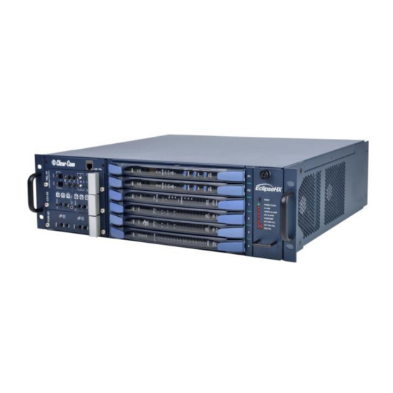
Chassis and assembly The matrix chassis is a metal rectangular box which measures three rack units (6RU) high and 19-inches wide (13.45 cm x 48.3 cm). The Eclipse HX-Delta has: • 2 CPU cards. • Slots for 4 interface cards, and 3 interface modules. -
Page 16: Eclipse Hx-Delta Front Panel
User Guide | Eclipse HX-Delta 3.3.2 Eclipse HX-Delta front panel Figure 3-1 EHX Delta front panel Page 16... - Page 17 Key: Eclipse HX-Delta front panel Feature Description Interface modules. The Eclipse HX-Delta can house up to 3 interface modules. Blank panels can be installed to unused slots. For more information, see 3.5 Interface modules. LAN / PNL connector. Front to rear Ethernet / panel feed through Interface cards.
- Page 18 For more information, see 5.7 Power status and alarm lights. Handle. There are handles on either side of the matrix to facilitate placing and removing the Eclipse HX-Delta in the 19” rack. Table 3-2: Key to Eclipse HX-Delta front panel...
-
Page 19: Eclipse Hx-Delta Rear Panel
User Guide | Eclipse HX-Delta 3.3.3 Eclipse HX-Delta rear panel Figure 3-2 Eclipse HX-Delta rear panel Page 19... -
Page 20: Power Supplies
3.3.4 Power supplies The Eclipse HX-Delta matrix has two external 12V power supplies for redundant operation. One power supply unit can power an entire matrix. The second unit provides a backup in case of failure or damage to the first unit. -
Page 21: Cpu Card
3.3.6 CPU card Two CPU cards are fitted to each Eclipse HX-Delta, in a master and slave relationship. The second CPU card provides redundancy in the case of outages or planned maintenance. The master CPU card:... -
Page 22: Interface Cards
Note: The term central matrix is used to differentiate the core hardware and software from the connected intercom panels and interfaces. The central matrix itself consists of the matrix hardware (in this case, the Eclipse HX-Delta) and the EHX configuration software. -
Page 23: E-Fib Fiber Interface Card
User Guide | Eclipse HX-Delta 3.4.1.1 Intelligent linking For intelligent linking, shielded CAT5 cable is run from a port on one Eclipse HX- Delta matrix to a port on a second Eclipse HX-Delta matrix to form a trunkline connection. 3.4.2 E-FIB fiber interface card E-FIB fiber interfaces connect Eclipse HX matrices together to provide a high speed, dual redundant link to transfer audio samples and data between systems. -
Page 24: Ip Interface Card
3.4.6 LMC-64 metering card The LMC-64 interface allows the Eclipse HX-Delta to provide Production Maestro Pro (routing software) clients with audio level metering of partylines (conferences) and four-wire ports over an IP network. The card supports both direct and trunk connections. -
Page 25: E-Dante64-Hx Interface Card
3.4.7 E-DANTE64-HX interface card This is a Clear-Com matrix interface card that is enabled to work with Dante network protocols and software. Using the E-Dante64 card you can transport many channels of high quality audio via a Clear-Com matrix to multiple Dante enabled devices using standard Ethernet network structure (up to 64 channels per E-DANTE64 card). -
Page 26: Ehx Configuration Software
AES-3 option card. It may also be used with AES-3 compliant third party equipment. Note: Additional interface modules may be added to the Eclipse HX-Delta, using separate interface module frames such as the IMF-3 and IMF-102. For more information, see the dedicated user guide / manual for that particular interface frame. -
Page 27: User Panels
The EHX system can be set up to run on a client/server model over a network, allowing the system administrator to control multiple matrices remotely. User panels The following Clear-Com user panels are compatible with the Eclipse HX-Delta: • V-Series panels, including expansion panels. • i-Series panels, including expansion panels. -
Page 28: Installing The Eclipse Hx-Delta
Note: The Eclipse HX distributor is not responsible for shipping damage. 4.1.2 Unpacking the System When the Eclipse HX-Delta system is received the CPU cards and interface cards, power supplies, and rear-connector panels are pre-installed in the matrix chassis. The customer must supply: •... - Page 29 The battery is now powered. Figure 4-1: CPU card with detail of CON9 jumper plugs Eclipse HX-Delta CPU cards are fitted with a socketed battery, normally a Renata CR2477N with a capacity of 950mAh and a life of approximately 247 days. These socketed batteries are easily replaced and this operation does not have to be carried out by service personnel.
- Page 30 LED. If EHX is logging, then the following message will appear in the log. Non Volatile Data is invalid - Please check Battery Voltage If on successive power downs of the Eclipse HX-Delta matrix the above state is detected, and the message appears in EHX logs, then it is advisable to check the health of the CPU card on board battery, which should be nominally at least 2.8V.
-
Page 31: Installing The Eclipse Hx-Delta
When the matrix is connected to the power supplies, connect the power supplies to AC mains power. A fully equipped Eclipse HX-Delta matrix (2 CPU cards, 4 interface cards and 3 interface modules) requires 100 - 240 VAC at 50 - 60 Hz with a maximum dissipation of 175W. -
Page 32: Installing The Rear Panels
• E-MADI64 rear cards have a MADI fiber connector, MADI input and output coaxial cable connectors, and a coaxial Video / Word clock input. Note: Clear-Com ships each matrix with the required number of rear-connector panels already installed. Blank rear panels fill unused card slots. -
Page 33: Hot Patching Cpu Cards
User Guide | Eclipse HX-Delta Figure 4-2: CPU card DIP switches set for normal operation Note: Store spare CPU cards in unused slots in the matrix or in electrically insulated packaging such as anti-static heavy duty plastic bags. To insert a CPU card in the matrix: Carefully place the card in the appropriate slot. -
Page 34: Checking The Cpu Card Installation
User Guide | Eclipse HX-Delta automatically begin operating when the first card is removed. It is advisable to replace CPUs in maintenance down times. 4.3.2 Checking the CPU Card installation The following lights indicate that the card has been properly installed in the... -
Page 35: Installing Interface Cards
4.4.3 Combining interface cards in the matrix The Eclipse HX-Delta can allocate up to 496 audio ports in total. However, the number of ports that you actually use will depend on the combination of interface cards you fit to the matrix. -
Page 36: Static Sensitivity
User Guide | Eclipse HX-Delta • Fitting 4 MVX-A16 cards to the Eclipse HX-Delta would fill the frame, but would only use 64 ports from the possible - ports available: 4 MVX cards * 16 ports = 64 More ports can be utilized on the Eclipse HX-Delta by using higher capacity interface cards, such as the E-MADI64 card. -
Page 37: Hot Patching (Hot Plugging)
User Guide | Eclipse HX-Delta handling a card, be careful not to bend any of the card’s connector pins or component leads. Store spare cards in electrically insulated packaging, such as anti-static heavy duty plastic bags or in unused card slots (though not fully seated) in the matrix. -
Page 38: Wiring Audio Devices To The Matrix
User Guide | Eclipse HX-Delta RESET One of the four power-supply lights Is lit to indicate that the associated power supply is operating properly. +12V -12V +3.3V The VOX lights corresponds to the card’s 16 ports. When lit, a VOX light indicates the audio... -
Page 39: Wiring Panels To The Matrix
-12, -9, -6, -3, 0, +3, +6, +9, +11 dB. Figure 4-5: Direct matrix port connection Clear-Com recommends the use of shielded cable. Note: The Eclipse HX Installation Guide gives complete details about wiring audio devices to the matrix. The installation guide also discusses RJ-45 cables and other types of cable required for system installation. -
Page 40: 4-Pair Analog
User Guide | Eclipse HX-Delta 4.6.1 4-Pair analog Four-pair analog wiring is performed with shielded CAT5 RJ-45 cable: Pair Description Pair 1 Transmits analog audio from the matrix to the panel. Pair 2 Transmits digital data from the panel back to the matrix. -
Page 41: Wiring Cpu Card Interfaces
Figure 4-7: Wiring the matrix to a digital panel using RJ-45 Note: Important. The above wiring diagram refers to DIG-2 and is shown as an example only (DIG-2 panels are not compatible with the Eclipse HX-Delta. Wiring CPU card interfaces... -
Page 42: Cpu Card Interface Connectors
User Guide | Eclipse HX-Delta 4.7.1 CPU card interface connectors GPI/ RLY INTERFACE RS-232 ALARM I/O GP-OUT GP-IN LAN1 LAN2 Figure 4-8: CPU card interface connectors Page 42... - Page 43 For more information about the GPI-6 and RLY-6 cards, consult their respective manuals in the Eclipse HX documentation set. Clear-Com recommends the use of shielded cable. For wiring pinout information for GPI/RLY interfaces, see: •...
- Page 44 User Guide | Eclipse HX-Delta Matrix Frame Computer Serial Port DB-9F "IBM-PC RS-232" Cable Connector DB-9M Cable Connector Receive (RXD) Transmit (TXD) Transmit (TXD) Receive (RXD) Ground (GND) Figure 4-9: Wiring the matrix DB-9M to the PC DB-9F Matrix Frame Computer Serial Port DB- "IBM-PC RS-232"...
- Page 45 A logic low or an open circuit means that the matrix will not detect an alarm condition. Pin 1 is a voltage source out of the Eclipse HX-Delta matrix. It is connected through a 10Kohm pull-up resistor to the +5 V supply rail inside the Eclipse HX-Delta matrix.
- Page 46 User Guide | Eclipse HX-Delta Figure 4-11: Wiring the Alarm I/O DB-9F to the Alarm Relay connector Figure 4-12: Double-pole double-throw alarm relay General-Purpose Outputs Connector (GP OUT) A GPO can be programmed to mute a speaker, to turn on an applause light, to turn on a door lock, or to perform a variety of other functions.
- Page 47 User Guide | Eclipse HX-Delta associated common pin on the GP OUT connector will be shorted to the relevant normally closed pin. When a general- purpose output becomes active, the short between the common pin is broken and a new connection is made between the common pin and the normally open pin.
- Page 48 User Guide | Eclipse HX-Delta The general-purpose inputs operate in one of two modes: the opto-isolated mode or the non-isolated mode. The opto-isolated mode requires the externally connected equipment to provide the current to power the general-purpose input. The non-isolated mode does not require that the externally connected equipment powers the general-purpose input.
- Page 49 User Guide | Eclipse HX-Delta To cause an input to detect an active signal in non-isolated mode, the current must flow from the relevant input pin. The external device should draw no current to cause an inactive input and at least 5 mA to cause an active input. The opto- isolator drive line contains a 1.5 kOhm resistor to limit the...
- Page 50 (LAN) to the CPU card through a standard Ethernet connection. green LED indicates the port is connected and the amber LED indicates activity. Clear-Com recommends the use of shielded cable. Local Area Network connector (LAN2) The LAN1 and LAN2 connectors have standard Ethernet pin assignments. The green...
- Page 51 User Guide | Eclipse HX-Delta Figure 4-17: LAN1 and LAN2 pin assignments Clear-Com recommends the use of shielded cable. Table 4-3: Key to CPU card interface connectors Page 51...
-
Page 52: Dse1/T1 Matrix To Matrix Crossover Cable Connections
User Guide | Eclipse HX-Delta DSE1/T1 Matrix to Matrix crossover cable connections For E1 and T1 direct matrix to matrix connections the CAT5 crossover cables should be wired, as shown in the table below: Matrix 1 Pin Description Matrix 2 Pin... - Page 53 User Guide | Eclipse HX-Delta The E1 pinout for connecting an antenna or splitter is shown in Table 4-6 E1 pinout for connecting a FreeSpeak / CellCom / FreeSpeak II antenna or splitter. Cable wiring is shown in Table 4-7: E1 to FreeSpeak / CellCom / FreeSpeak II antenna or splitter straight cable connection.
-
Page 54: Using The Eclipse Hx-Delta
CD-ROM for later use. Note: The CPU card in the Eclipse HX-Delta stores up to four complete configurations. You can apply a configuration directly from the CPU card or from the connected... -
Page 55: Configuration Restrictions For Ethernet Ports
User Guide | Eclipse HX-Delta If an IP address of is configured on the second Ethernet port, it will 0.0.0.0 not be used for Tx or Rx. This is the default setup if the default IP address is set as described above. - Page 56 User Guide | Eclipse HX-Delta An Eclipse HX-Delta system operates with either one or two CPU cards. When a second card is installed, that card stores the four configurations in its RAM as a backup to the main card. If the main card is removed or becomes non- operational for any reason, the system will automatically switch to the second card as backup.
-
Page 57: Cpu Card Lights And Controls
User Guide | Eclipse HX-Delta CPU card lights and controls RESET +3.3V MASTER LAN A LAN B IN SYNC CONFIG RESET Figure 5-1: CPU card lights and controls Page 57... - Page 58 User Guide | Eclipse HX-Delta Key to CPU card lights and controls Feature Description RESET button Pressing the RESET button causes the CPU card to stop its current activity and to restart. The same configuration that was active before the system was reset will be active after the system was reset.
- Page 59 CPU cards are exchanging information. Master Light An Eclipse HX-Delta system can have two CPU cards, although the system will operate with only one. If the primary card becomes unavailable for any reason, the second card can serve as backup while the primary card is repaired or replaced.
- Page 60 User Guide | Eclipse HX-Delta Configuration [ CONFIG ] button The CPU card can hold four complete system configurations in its operational memory. When the CONFIG button is pressed the number of the currently active configuration (either 1, 2, 3, or 4) appears in the dot-matrix display.
-
Page 61: Using The Embedded Configuration
User Guide | Eclipse HX-Delta • System number. This is only output if the rack is part of a linked set. It is the system number of the node within the linked set (for example, SYSTEM 3). • Software version number. Version number of the config card software (for example, RACK 1.0.2.1). - Page 62 User Guide | Eclipse HX-Delta On the front of the CPU card, press and hold the CONFIG and the ENG buttons. Simultaneously, reset the CPU card by pressing and holding the CPU card’s lower RESET button (the Full reset button).
-
Page 63: Mvx-A16 Analog Card Front-Panel Lights And Controls
User Guide | Eclipse HX-Delta MVX-A16 analog card front-panel lights and controls RESET +12V -12V +3.3V ACTIVE VOX FRAME STATUS DATA Figure 5-2: MVX-A16 analog card front panel lights and controls Page 63... - Page 64 User Guide | Eclipse HX-Delta Key to MVX-A16 analog card lights and controls Feature Description RESET button Pressing the RESET button causes the card and all connected audio devices to momentarily stop their current activity and to restart. The card’s “matrix data” light goes off when the reset starts and comes back on when the reset is complete.
-
Page 65: Power Status And Alarm Lights
Note: The location of the power status lights, the alarm lights and the reset button are shown in Figure 3-1 EHX Delta front panel. The front panel of the Eclipse HX-Delta displays power status and alarm lights. An alarm source turns on the main alarm light [Alarm] (and an audible warning) and one of the alarm lights dedicated to a specific alarm condition. - Page 66 User Guide | Eclipse HX-Delta • If either of the matrix’s two cooling fans stop operating. • If the temperature inside the matrix exceeds a set threshold. 5.7.2.1 Alarm reset button When the alarm reset button is pressed the following events take place, even if the alarm condition has not been corrected: •...
-
Page 67: Connecting The Matrix
Connecting the matrix Note: For detailed information about connecting the matrix to user panels, interfaces and other devices, see 4 Installing the Eclipse HX-Delta in this document. The Eclipse HX-Delta matrix connects to devices such as the external computer that runs the EHX configuration software, panels, interfaces, and other matrices through its rear-panel hardware connectors, often called ports. -
Page 68: Connecting The Cpu Card
CPU cards is acting as master will work in conjunction with this card. All other front cards, however, require their own rear-connector panel. Note: For detailed information about connecting the matrix to panels, interfaces and other devices, see 4 Installing the Eclipse HX-Delta. Page 68... -
Page 69: Connecting Interface Cards
Each rear connector panel associated with an E-FIB interface holds two fiber ports (TXVRA and TXVRB). Note: For detailed information about connecting the matrix to user panels, interface modules and other devices, see 4 Installing the Eclipse HX-Delta in this document. Page 69... -
Page 70: Madi64 Card
User Guide | Eclipse HX-Delta E-MADI64 card The E-MADI64 is a MADI (Multichannel Audio Digital Interface) card, providing up to 64 duplex channels of AES3 digital audio over a coaxial cable or fiber pair between compatible devices. The card supports both direct and trunk connections. -
Page 71: E-Madi64 Front Panel Lights And Controls
User Guide | Eclipse HX-Delta E-MADI64 front panel lights and controls RESET +3.3V LOCK VID WRD 44.1 CHANNELS ERROR ACTIVE E-MADI Figure 6-1: E-MADI64 front panel lights and controls Page 71... - Page 72 User Guide | Eclipse HX-Delta Note: Figure 25 shows an unconfigured E-MADI64 card, when all lights are lit to indicate their location. On a card with a clock source and MADI connections ( where the received MADI signal matches the card set up), the following lights are lit: the Lock source LED [ C ], the Sample rate (Fs) LED [ D ], the Channels LED [ E ] and the Active LED [ F ].
- Page 73 User Guide | Eclipse HX-Delta Channels green LED indicates the quantity of MADI channels. The number of channels is determined in EHX. You can select from 32, 56 or 64 full duplex channels of digital audio. Channel LEDs on the front of the E-MADI card will oscillate...
-
Page 74: E-Madi64 Rear Panel Connectors
User Guide | Eclipse HX-Delta E-MADI64 rear panel connectors E-MADI MADI MADI IN MADI OUT CLOCK Figure 6-2: E-MADI64 rear panel connectors Page 74... -
Page 75: Madi Channels
Note: The channel modes for the E-MADI64 are 32, 56 and 64. For more information, see Table 6-3: E-MADI64 channel modes. Each MADI audio channel: • Carries one (or a mixture of) any of the 512 Eclipse HX-Delta backplane timeslots. • Is 24 bits in length. -
Page 76: Madi Channel Labelling
Setting up the E-MADI64 card To set up the E-MADI card: With the Eclipse HX-Delta powered off, insert the E-MADI front and rear cards into the matrix. Note: The number of E-MADI64 cards you can fit to the matrix is limited by the available port count. -
Page 77: Connecting A Word Clock Source
User Guide | Eclipse HX-Delta Note: Card Properties permits sample rate selection when synching to video signals. It is only used when not using the Word Clock Source Sync (see below). Note: Card Properties always defaults to the E-MADI64 standard for... -
Page 78: V-Series Panels On E-Madi (Multi-Channel Audio Digital Interface)
User Guide | Eclipse HX-Delta The sample rate and the number of configured ports is indicated by a solid green LED on the front of the E-MADI64 card. Error LED on the E-MADI64 card is turned off. When the number of received channels differs from the number of... -
Page 79: Configuring Audio Over Optocore/Progrid Madis
User Guide | Eclipse HX-Delta 2. Set alternate ports to panels 1. Set card type To configure binaural audio on V-series panels on a MADI card in EHX go to: EHX>Hardware>Cards and Ports. This example shows how to configure ports for audio streamed in pairs, A and B. -
Page 80: Configuring Binaural Audio With E-Madi Cards
User Guide | Eclipse HX-Delta In all cases, when using a router such as ProGrid, ensure that the configuration of the E-MADI card and the configuration of the ProGrid matrix are consistent with each other. 2. Set ports in any order 1. -
Page 81: Configuring Binaural Panel Audio In Software
User Guide | Eclipse HX-Delta • Use a headset with a minimum of a 5-pin input (use with an XLR5 or 7 adapter). Configuring binaural panel audio in software The main audio channel and the auxiliary audio channel need to be directed to the desired ports. -
Page 82: Binaural Audio Over Optocore/Progrid Madis
User Guide | Eclipse HX-Delta 6.7.2 Binaural audio over Optocore/ProGrid MADIs Optocore/ProGrid MADIs allow each channel of the MADI to be routed individually to any channel of any destination. The AES streams do not have to be routed and configured in pairs. The ProGrid equipment allows fully flexible routing and it is possible to mix close packed mono and conventional stereo pairs on one MADI interface. -
Page 83: Upgrading The E-Madi64 Card
User Guide | Eclipse HX-Delta Select Configuration>Panels>Audio Mixer>Layout Basic Settings>Layout Binaural coax/AES Figure 6-6 Set binaural viewing options in the audio mixer Set audio routes as required (see EHX User Guide, 8. Audio Mixer for more information). Upgrading the E-MADI64 card... -
Page 84: Fib Fiber Card
If fiber interfaces are fitted to any matrix in a linked system all the linked matrices must be reset to ensure that all matrices correctly recognize the new hardware. Note: For an overview of the Eclipse HX-Delta, see 3 Overview in this document. Page 84... -
Page 85: E-Fib Front Panel Lights And Controls
User Guide | Eclipse HX-Delta E-FIB front panel lights and controls RESET +3.3V PROC FRONT REAR TXVRA ACT LINK ERR TXVR TXVRB ACT LINK ERR TXVR STATUS FRAME DATA Figure 7-1: E-FIB front panel lights and controls Page 85... - Page 86 User Guide | Eclipse HX-Delta Key to E-FIB front panel lights and controls Feature Description RESET button Pressing the RESET button causes the card and all links to momentarily stop their current activity and to restart. The card’s matrix data light goes off when the reset starts and comes back on when the reset is complete.
- Page 87 User Guide | Eclipse HX-Delta ERR LED This LED will be illuminated if an error condition is detected on the primary fiber optic circuit. Secondary Link Status LEDs These LEDs indicate the status and functioning of the secondary (B) fiber optic link.
-
Page 88: E-Fib Rear Panel Lights And Connectors
User Guide | Eclipse HX-Delta E-FIB rear panel lights and connectors +3.3V TXVRB Transceiver lasers TXVRA Figure 7-2: E-FIB rear panel lights and connectors Warning: Eye Safety This laser based single mode transceiver is a Class 1 Laser product. It... - Page 89 User Guide | Eclipse HX-Delta products (21 CFR 1040.10 and 1040.11) except for deviations pursuant to Laser Notice 50, dated July 26, 2001. Normally a protective plug is fitted to the fiber connector to protect the connector from damage or the entry of foreign materials. The protective plug should only be removed in order to fit the fiber optic cable.
-
Page 90: Configuring A Fiber Optic Connection
User Guide | Eclipse HX-Delta System 1 System 2 Primary ring Redundant ring TXVRB TXVRB TXVRA TXVRA System 3 TXVRB TXVRA Figure 7-3: Primary and redundant ring configuration Configuring a fiber optic connection There are a number of ways that optical connections can be made between systems depending on the level of redundancy required. -
Page 91: Simplex Fiber Cabling
User Guide | Eclipse HX-Delta Simplex fiber cabling 7.4.1 Single card set redundancy In this scenario, each matrix contains one fiber-optic Linking card set (see Figure 7-4: Ring topology: single card set redundancy). This approach still affords fiber connection redundancy since each rear card houses two fiber-optic transceivers. -
Page 92: Dual Card Set Redundancy
User Guide | Eclipse HX-Delta The self-healing mechanism is performed automatically by the Fiber Linking Card. Switching to the secondary ring will cause audio breaks or disturbances and temporary loss of crosspoint data. If a single fiber connection is lost on both rings the nodes adjacent to the failures will loop-back their connections to the failed cables healing the rings. -
Page 93: Fault Tolerance
User Guide | Eclipse HX-Delta This approach affords full redundancy, offering protection against component failure within a single Fiber-optic Linking Card Set 7.4.2.1 Parallel operation The cabling and operation of both cards sets is the same as described in 7.4.1 Single card set redundancy. - Page 94 User Guide | Eclipse HX-Delta 7.4.3.1 Single Card Set Redundant System: fiber redundancy In all fault cases involving cable faults or loss of nodes on the ring the remaining nodes may experience audio breaks or disturbances and loss of crosspoint information or data.
- Page 95 User Guide | Eclipse HX-Delta System #1 System #2 System #3 TX2- E-FIB TX2- E-FIB TX2- E-FIB card#1 - RX2 card#1 - RX2 card#1 - RX2 TX1- E-FIB TX1- E-FIB TX1- E-FIB card#1 - RX1 card#1 - RX1 card#1 - RX1...
-
Page 96: Que E1/T1 Card
Note: You do not require an Ethernet cable connected to the E-QUE card LAN port for the card to function correctly. For an overview of the Eclipse HX-Delta matrix, see 3 Overview in this document. Page 96... -
Page 97: E-Que Front Panel Lights And Controls
User Guide | Eclipse HX-Delta E-QUE front panel lights and controls RESET +3.3V STATUS LAN DATA LINK Figure 8-1: E-QUE front panel lights and controls Page 97... - Page 98 User Guide | Eclipse HX-Delta Key to E-QUE front panel lights and controls Feature Description RESET button Pressing the reset button causes the card and all links to momentarily stop their current activity and to restart. During the reset, configuration information downloads to the card from the CPU card.
-
Page 99: E-Que Rear Panel Connectors
User Guide | Eclipse HX-Delta E-QUE rear panel connectors Ref in DECT Ref out E-QUE 1 – 4 5 – 8 Figure 8-2: E-QUE rear panel connectors Page 99... -
Page 100: E-Que Interface Card Applications
User Guide | Eclipse HX-Delta Key to E-QUE rear panel connectors Feature Description LAN port (RJ-45) The LAN port is used for diagnostic purposes. DECT sync ports: DECT Ref in DECT Ref out E1 / T1 Port 1 - 4(RJ-45) -
Page 101: Freespeak/Cellcom/ Freespeak Ii Application
User Guide | Eclipse HX-Delta Note: For more information about E1 and T1 cable pinouts and cable connections, see: • 4.9 E1/T1 Matrix to Matrix straight cable connections in this document. • 4.10 E1 to FreeSpeak / CellCom / FreeSpeak II antenna straight cable connection in this document. - Page 102 User Guide | Eclipse HX-Delta Figure 8-3: E-QUE card antenna connection Page 102...
- Page 103 User Guide | Eclipse HX-Delta Figure 8-4: E-QUE card splitter connection Each antenna can handle up to five beltpacks simultaneously and switch service between antennas under control of the matrix as the beltpack user moves around the site. The DC In power connector is used to locally power the transceiver/antenna with the supplied universal power supply.
-
Page 104: E1 Trunk And Direct Modes
User Guide | Eclipse HX-Delta Multiple E-QUE interface cards within a single matrix do not require external DECT sync cables, connected as the signal uses the backplane. Figure 8-5: Multiple matrices with DECT Sync Interconnect Note: All connections are made using CAT5 cable and it is recommended that shielded cable is used. - Page 105 User Guide | Eclipse HX-Delta third-party equipment. E1 mode provides 30 channels of G.722 or G.711 encoded audio available on each of ports 1 and 5, giving 60 channels per card. The E1 specifications are: • HDB3 Encoding. • Long Haul Receive Signal Level.
- Page 106 User Guide | Eclipse HX-Delta Figure 8-6: Matrix to Matrix direct E1 Trunking E1 trunking between matrices can also be achieved over an E1 network, as shown in Figure 8-7: E1 Trunking with an E1 Network. In this case E1 ports 1 and 5 of the E-QUE interface are connected using standard straight-through CAT5 cables rather than crossover CAT5 cables.
- Page 107 User Guide | Eclipse HX-Delta Figure 8-7: E1 Trunking with an E1 Network The E-QUE interface can also be used to connect the matrix to third party equipment using E1 port 1 or 5. Page 107...
-
Page 108: T1 Trunking
User Guide | Eclipse HX-Delta Figure 8-8: Matrix to Third Party E1 connection The CAT5 cable connecting the E1 port on the E-QUE rear card may be a crossover cable or a straight-through cable depending on the requirements of the third party equipment. The E-QUE interface should be set to Direct in EHX. - Page 109 User Guide | Eclipse HX-Delta • 120 Ohm Line Impedance. • No Signaling. • G.722 or G.711 64 kbit/s Audio Encoding. • Tx Clock locally generated. • Rx Clock Line Recovered. Figure 8-9: Matrix to Matrix T1 Trunking T1 trunking between matrices can also be achieved over an E1 network as shown in Figure 8-10: T1 Trunking using an E1 Network.
-
Page 110: Trunking Failover
User Guide | Eclipse HX-Delta Figure 8-10: T1 Trunking using an E1 Network Trunking failover Where the E1/T1 trunking has been configured with redundant trunks audio will be switched from the primary trunk to the backup trunk when a failure is detected. -
Page 111: Card For Ip-Based Connections
DECT sync in and out (not used) and a LAN port used for the IP connection. Note: An Ethernet cable must be connected to the IVC-32 interface LAN port for the card to function correctly. For an overview of the Eclipse HX-Delta, see 3 Overview in this document. Page 111... -
Page 112: Front Panel Lights And Controls
User Guide | Eclipse HX-Delta IVC-32 front panel lights and controls RESET +3.3V STATUS LAN DATA LINK Figure 9-1: IVC-32 front panel lights and controls Page 112... - Page 113 User Guide | Eclipse HX-Delta Key to Figure 41: IVC-32 front panel lights and controls Feature Description RESET button Pressing the reset button causes the card and all links to momentarily stop their current activity and to restart. During the reset, configuration information downloads to the card from the CPU card.
-
Page 114: Rear Panel Connectors
User Guide | Eclipse HX-Delta IVC-32 rear panel connectors Ref in DECT Ref out IVC-32 1 – 4 5 – 8 Figure 9-2: IVC-32 rear panel connectors Page 114... -
Page 115: Interface Applications
V-Series IP Panels V-Series panels with V5.1 or later software may be enabled to communicate with an Eclipse HX-Delta matrix over an IP network using the IVC-32 interface card. The advantage of using IP communication is that it enables remote panels to communicate over an existing local (LAN) or wide area (WAN) network rather than requiring a dedicated link. -
Page 116: Ip Linking And Trunking
User Guide | Eclipse HX-Delta 9.3.2 IP linking and trunking The Eclipse IVC-32 cards allow directs and trunks over IP network infrastructure. All IP trunks and directs can be compared directly to 4-wire trunks and directs. They consist of: • A single duplex audio channel •... -
Page 117: Metering Card
User Guide | Eclipse HX-Delta LMC-64 metering card The Level Meter Card (LMC-64) interface card enables the Eclipse HX-Delta to provide audio level metering for Production Maestro Pro over a network. Each LMC-64 interface card can meter up to 64 virtual partylines (conferences) and four-wire ports. -
Page 118: Front Panel Lights And Controls
User Guide | Eclipse HX-Delta 10.1 LMC-64 front panel lights and controls RESET +3.3V STATUS LAN DATA LINK Figure 10-1: LMC-64 front panel lights and controls Page 118... - Page 119 User Guide | Eclipse HX-Delta Key to IVC-32 front panel lights and controls Feature Description RESET button Pressing the reset button causes the card and all links to momentarily stop their current activity and to restart. During the reset, configuration information downloads to the card from the CPU card.
-
Page 120: Rear Panel Connectors
User Guide | Eclipse HX-Delta 10.2 LMC-64 rear panel connectors Ref in DECT Ref out LMC-64 1 – 4 5 – 8 Figure 10-2: LMC-64 rear panel connectors Page 120... -
Page 121: Interface Applications
User Guide | Eclipse HX-Delta Key to LMC-64 rear panel connectors Feature Description LAN port (RJ-45) DECT sync ports: DECT Ref in (Not used) DECT Ref out (Not used) E1 / T1 Port 1 - 4 (Not used) E1 / T1 Port 5 - 8(Not used) -
Page 122: Dante64-Hx Card
E-Dante64-HX card This section contains information about audio networking using an E-DANTE64- HX interface card. This is a Clear-Com matrix interface card that is enabled to work with Dante network protocols and software so that you can transport many channels of high quality audio via a Clear-Com matrix to multiple Dante enabled devices using standard Ethernet network structure (up to 64 channels per E-DANTE64 card). -
Page 123: Example Applications
User Guide | Eclipse HX-Delta 11.1 Example applications 11.1.1 Interruptible Foldback (IFB) over Dante Figure 11-1 IFB over Dante Page 123... -
Page 124: Live Performance Interface With Digital Intercom
User Guide | Eclipse HX Omega 11.1.2 Live performance interface with digital intercom Figure 11-2 Live performance interface with Clear-Com digital intercom Page 124... -
Page 125: Using The E-Dante64-Hx Card
11.2 Using the E-DANTE64-HX card To route audio using a Clear-Com Dante card you must already have the Audinate Dante Controller installed on your PC (or similar device that can set up Dante routes). The Dante Controller can be downloaded from the Audinate website. -
Page 126: E-Dante64-Hx Front Panel Lights And Controls
User Guide | Eclipse HX-Delta 11.3 E-DANTE64-HX front panel lights and controls Feature Description Reset button Pressing the Reset button causes the card and all links to momentarily stop their current activity and to restart. The flashing green Active light goes off when the reset starts and comes back on when the reset is complete. - Page 127 User Guide | Eclipse HX-Delta 100Mbps will only support a small number of Dante channels. A Fiber connection is always 1Gbps and is always green. Active LED The Active (matrix data) LED flashes green (1:1 at 1Hz) to indicate successful communication between the E-DANTE64-HX interface and the CPU card.
-
Page 128: E-Dante64-Hx Rear Panel Lights And Controls
Feature Description Secondary network connector RJ45 See Note below. Secondary network connector Fiber In this slot you will install a Clear-Com SFP/Mini- GBIC. See Specifications section for details. Secondary Fiber connection LEDs green LED indicates that the network (Primary or Secondary) is successfully connected. -
Page 129: Network Configuration
PCs and printers often do. See Audinate Dante Controller User Guide, 2016 Audinate Pty Ltd. Note: DHCP is the preferred method of IP allocation when using Dante. Clear-Com recommends that the Eclipse Matrix (LAN) IP address uses a fixed/static IP address. 11.6... -
Page 130: Upgrading Your E-Dante64-Hx Card
The upgrade process for each of the two modules on the card (EHX and Dante) is different. The two processes are outlined below. Note: When upgrading your E-Dante64 card, only use the Clear-Com supplied upgrade files for both (A: EHX) ClearCom - App, Boot, DSP, FPGA: xxxxxx.FWC files (B: Dante) ClearCom [Brooklyn]: xxxxxx.dnt file. - Page 131 Note: The EHX component of the E-Dante64 card is both centrally upgradable (you can upgrade the E-Dante64 through the matrix, using EHX) and locally upgradeable, using Xilinx software, a PC and a Xilinx download cable. The process is the same as for a Clear-Com MADI card. Page 131...
-
Page 132: Upgrade Dante Firmware
User Guide | Eclipse HX-Delta For more information, see the Eclipse HX Upgrade Guide and refer to the section on MADI. 11.7.2 Upgrade Dante firmware Before updating the Dante component of your E-DANTE64 card, you must first download the Dante Firmware Update Manager from the Audinate website. -
Page 133: Find The Device Ip Address
User Guide | Eclipse HX-Delta Cards that have been ‘misplaced’ and are not visible in the routing screen are those that have been configured with a static IP address that falls outside the subnet which the PC hosting the controller is on. -
Page 134: Make Sure Both Devices Are On The Same Subnet
User Guide | Eclipse HX-Delta Figure 11-5 Find IP address 2 11.9.2 Make sure both devices are on the same subnet In order to be able to configure the E-Dante card as usual, you must make sure that the PC hosting the controller is in the same IP range (subnet) as the card. -
Page 135: Link-Local
User Guide | Eclipse HX-Delta Figure 11-6 Reset IP address 11.9.4 Link-local The link-local IP range is a special case (169.254.1.0 – 169.254.254.255). The Dante Controller will NOT see an E-Dante64 card with a link-local IP address if the PC hosting it is not set to the link-local IP range also. In this case, you need to change the PC’s IP address to a value in the link-local range... -
Page 136: Aes67 Guidelines
User Guide | Eclipse HX-Delta 11.9.5 AES67 Guidelines When connecting devices to route AES67 audio streams with your E-DANTE 64 card, the following general principles should be noted: • AES67 uses IEEE1588-2008 Precision Time Protocol (PTP) to ensure synchronization between devices. All networked devices, including your network switch must support this standard. - Page 137 User Guide | Eclipse HX-Delta • Dante uses Session Announcement Protocol (SAP) to discover devices on a network. If any of your devices do not support SAP, the Dante Controller will not be able to see them. In this case, you need to use a...
-
Page 138: Ipa-Hx High Capacity Ip To Matrix Card
The E-IPA-HX card is a high-capacity internet protocol (IP) audio card. It provides up to 64 connections. The card offers both IVC ports and Clear-Com FreeSpeak II IP Transceiver (IPT) connectivity. This can be a combination of up to 64 IP ports or FreeSpeak II wireless beltpack connections (according to license). -
Page 139: Adding An E-Ipa-Hx Card (Manual)
User Guide | Eclipse HX-Delta • You select the Discover Hardware option after the Matrix is placed on the System Layout from the discovery pane. • You right-click a matrix on the System Layout screen, and then select Configuration > Create New Configuration > Discover Hardware. - Page 140 User Guide | Eclipse HX-Delta You can also use the Detect New Hardware feature in EHX to discover the card. Use this feature if the hardware is installed before the software is configured. This feature auto-detects the number of ports available on the card.
- Page 141 User Guide | Eclipse HX-Delta Figure 12-1 Hardware change If your configuration contains linked matrices, the following message might appear when you apply changes to the matrix: Figure 12-2 Configuration may affect other matrices Click View Configuration Differences to see a list of possible interconnection issues.
-
Page 142: Network Setup For The E-Ipa-Hx Card
User Guide | Eclipse HX-Delta Figure 12-3 E-IPA-HX Card Properties Change the edit fields as required, and then click Close. Note: To view and edit the E-IPA-HX card properties at any time, double click on the E-IPA-HX Card Slot or right-click and select Card Properties. -
Page 143: Network Setup For Clear-Com Ivc Functionality
15) IVC: V Series panels, Trunking, Directs, Agent-IC, LQ. 16) AES67: data and audio connection between the E-IPA-HX card and the IP Transceivers (IPTs). Functionality and IP ports can be combined, but Clear-Com recommends certain rules for set up to avoid loss of functionality and IP clashes. 12.2.1... -
Page 144: Network Setup For The Freespeak Ii Ip Transceiver (Ipt) With E-Ipa-Hx Card
User Guide | Eclipse HX-Delta You can separate Admin from IVC connectivity, but if you do this, you must put administration functions and IVC functionality on separate subnets. In this case, the Admin connection can be given a DHCP IP setting, while the IVC connection must have a static IP address. -
Page 145: Licenses
User Guide | Eclipse HX-Delta • Clear-Com recommends that AES67 ports are on a separate network from the Admin and IVC ports. • AES67 connections can work in the link-local range of IP addresses (169.254.XXX.XXX). • When configuring an AES67 network, the network switch must have DiffServ Quality of Service (QoS) switched on. -
Page 146: Card Capacity
IPT are connected to the card. Concert is NOT supported on the E-IPA-HX card. 12.4.1 How many E-IPA cards in a Clear-Com matrix? • Clear-Com Omega and Median matrices: up to four E-IPA cards per matrix Page 146... - Page 147 User Guide | Eclipse HX-Delta • Clear-Com Delta matrix: up to three E-IPA cards per matrix Note: This is an estimate for general guidance. For a more exact calculation, refer to the Eclipse HX System Power Calculator (Excel spreadsheet) that comes with your EHX firmware. You can find this spreadsheet in the Documents folder on the firmware DVD or USB.
-
Page 148: E-Ipa-Hx Rear Connectors
User Guide | Eclipse HX-Delta 12.5 E-IPA-HX rear connectors Page 148... - Page 149 User Guide | Eclipse HX-Delta RJ45 LAN ports 1 – 4. These can be used for: Clear-Com panels, directs, trunks, LQ, Agent-IC. They can also be used for FSII IP Transceivers. One of the ports can be designated as an ADMIN port and used for maintenance. The functionality of these ports is configured in the EHX software.
-
Page 150: E-Ipa-Hx Front Lens Indicators
User Guide | Eclipse HX-Delta 12.6 E-IPA-HX front lens indicators Page 150... - Page 151 LED indicates 100Mbps connection. An LED lit green indicates 1Gbps connection. For FS II, Clear-Com does not recommend using less than 1Gbps in most circumstances, as 100Mbps only supports a small number of channels. A fiber connection is always 1Gbps and is always green.
-
Page 152: Adding An E-Ipa-Hx Card (Automatic Discovery)
User Guide | Eclipse HX-Delta 12.7 Adding an E-IPA-HX card (automatic discovery) The E-IPA-HX card is automatically discovered when: • You select the Discover Hardware option after the Matrix is placed on the System Layout from the discovery pane. •... - Page 153 User Guide | Eclipse HX-Delta You can also use the Detect New Hardware feature in EHX to discover the card. Use this feature if the hardware is installed before the software is configured. This feature auto-detects the number of ports available on the card.
- Page 154 User Guide | Eclipse HX-Delta Figure 12-1 Hardware change If your configuration contains linked matrices, the following message might appear when you apply changes to the matrix: Figure 12-2 Configuration may affect other matrices 20) Click View Configuration Differences to see a list of possible interconnection issues.
-
Page 155: Network Setup For The E-Ipa-Hx Card
User Guide | Eclipse HX-Delta Figure 12-3 E-IPA-HX Card Properties Change the edit fields as required, and then click Close. Note: To view and edit the E-IPA-HX card properties at any time, double click on the E-IPA-HX Card Slot or right-click and select Card Properties. -
Page 156: Network Setup For Clear-Com Ivc Functionality (V Series Panels, Directs, Trunks, Lq And Agent-Ic)
26) IVC: V Series panels, Trunking, Directs, Agent-IC, LQ. 27) AES67: data and audio connection between the E-IPA-HX card and the IP Transceivers (IPTs). Functionality and IP ports can be combined, but Clear-Com recommends certain rules for set up to avoid loss of functionality and IP clashes. 12.9.1... -
Page 157: Network Setup For The Freespeak Ii Ip Transceiver (Ipt) With E-Ipa-Hx Card
User Guide | Eclipse HX-Delta You can separate Admin from IVC connectivity, but if you do this, you must put administration functions and IVC functionality on separate subnets. In this case, the Admin connection can be given a DHCP IP setting, while the IVC connection must have a static IP address. -
Page 158: Port Security Settings
User Guide | Eclipse HX-Delta • Clear-Com recommends that AES67 ports are on a separate network from the Admin and IVC ports. • AES67 connections can work in the link-local range of IP addresses (169.254.XXX.XXX). • When configuring an AES67 network, the network switch must have DiffServ Quality of Service (QoS) switched on. -
Page 159: Upgrade The E-Ipa-Hx Card
User Guide | Eclipse HX-Delta Port Setting Admin/IVC DHCP (67, 68) mDNS (5353) HTTP (80, 8080, 443) rsync (873) IVP (6001). IVP port is configurable. AES67 DHCP (67, 68) PTP (319, 320) mDNS (53, 53) IVP (6001) HTTP (80, 80) 12.11... - Page 160 User Guide | Eclipse HX-Delta If there is an interruption to the power supply of the E-IPA-HX card during the upgrade, the card will go into recovery mode. The table below shows the stages that occur during recovery mode. State\ LED...
- Page 161 User Guide | Eclipse HX-Delta ( < 1 minute) Writing zImage ( < 1 minute) Writing FPGA image ( 1 minute) Fetching rootfs (~ 10 seconds) Writing rootfs ( < 5 minutes) All done! Check the firmware report to make sure that the upgrade has completed successfully.
-
Page 162: Maintaining The Eclipse Hx-Delta
Once the circuit board has been identified, it can be either repaired or replaced. For an overview of the Eclipse HX-Delta, see 3 Overview in this document. Servicing instructions are for use by qualified personnel only. -
Page 163: Fail-Safe Modes
• One fan card assembly. • One PSU card assembly. 13.2 Fail-Safe modes High reliability is one of the main objectives of the Eclipse HX-Delta system design. The following features of the system minimize the effects of a component failure. 13.2.1 Dual power supplies The Eclipse HX-Delta matrix includes two external power supply units. -
Page 164: Hot Patchability
User Guide | Eclipse HX-Delta 13.2.2 Hot patchability The front panels of CPU cards and interface cards (not rear panels), and all external power supplies and fan card assembly are hot patchable– that is, they can be plugged in or removed from the matrix while the power is on, and they will be neither damaged, nor will they cause damage to the system. - Page 165 User Guide | Eclipse HX-Delta Note: Clear-Com may ship a spare matrix to use while the damaged matrix is being repaired depending on the support status. For more information, see your warranty and support documentation. 13.3.1.1 Power supply lights on a component A lit power-supply light on a component indicates that the matrix’s electric...
- Page 166 User Guide | Eclipse HX-Delta Note: Clear-Com may ship a spare matrix to use while the damaged matrix is being repaired depending on the support status. For more information, see your warranty and support documentation. Action 2: Take a known good card, and insert it into the slot.
- Page 167 In the meantime another matrix can be substituted for the damaged one. Note: Clear-Com may ship a spare matrix to use while the damaged matrix is being repaired depending on the support status. For more information, see your warranty and support documentation.
-
Page 168: Troubleshooting Data Issues
User Guide | Eclipse HX-Delta 13.3.2 Troubleshooting data issues The other type of problem that can occur in the system is when data is not flowing properly between the program software, the circuit cards, and the attached panels and interfaces. A troubleshooting sequence in this situation would be to first check cabling, then reset the card or panel, then reset the entire system. - Page 169 User Guide | Eclipse HX-Delta is downloaded to the port cards and connected audio devices from the CPU card’s microprocessor. The same system configuration that was active before the card was reset will be active after the reset. The button must be pressed for more than two seconds for the reset to take effect.
-
Page 170: System Block Diagram
User Guide | Eclipse HX-Delta 13.4 System block diagram LAN1, LAN2 GPI, GPO, GPI/RLY, INTERFACE TO RS232 SERIAL & GPI/RLY & ALARM 2/4 WIRE EXTERNAL INTERFACES INTERFACES PSUS MVX- E-QUE E-FIB MADI64 CONFIG REAR REAR POWER REAR REAR REAR CARD... -
Page 171: Compliance
0-9, A-Z). All IC0XX SELV interface cards are compliant with regulatory requirements detailed in this document when installed correctly in Clear-Com product per Clear-Com specifications. Caution: Product modification not expressly approved by the party responsible for compliance can void the user’s authority to operate the equipment... - Page 172 The European Union (EU) WEEE Directive (2012/19/EU) places an obligation on producers (manufacturers, distributors and/or retailers) to take-back electronic products at the end of their useful life. The WEEE Directive covers most Clear-Com products being sold into the EU as of August 13, 2005. Manufacturers, distributors and retailers are obliged to finance the costs of recovery from municipal collection points, reuse, and recycling of specified percentages per the WEEE requirements.
- Page 173 User Guide | Eclipse HX-Delta will help to conserve natural resources and ensure that it is recycled in a manner that protects human health and the environment. For more information about where you can drop off your waste equipment for recycling, contact your local authority, your household waste disposal service or the seller from whom you purchased the product.
-
Page 174: Specifications
User Guide | Eclipse HX-Delta Specifications 0 dBu is referenced to 0.775 volts RMS. 15.1 Matrix capabilities Category Number / Comments Maximum Interface Cards Ports per MVX-A16 Card Maximum MVX-A16 Cards Maximum CPU Cards 2 (included) Maximum Fiber Interface Cards... -
Page 175: Matrix Performance
User Guide | Eclipse HX-Delta Storage Temperature -55º C to +70º C Humidity, Maximum 90% non-condensing Table 15-3: Environmental 15.4 Matrix performance Category Measures / Comments Sample Rate 48 kHz Resolution 24 bit Frequency Response 30 Hz – 22 kHz ± 3 dBu... -
Page 176: E-Madi64 Interface Rear Card
User Guide | Eclipse HX-Delta 15.6 E-MADI64 interface rear card Category Measures / comments Height Depth 58mm (max) Operating Temperature 0º C to +40º C Storage Temperature -55º C to +70º C Humidity 40 - 90% non-condensing Power +3.3V Table 15-6: E-MADI64 interface rear card 15.7... -
Page 177: E-Madi64 Clock Sources
User Guide | Eclipse HX-Delta 15.9 E-MADI64 clock sources Clock type Clock source Word Clock 44.1KHz 48KHz 96KHz SD Video NTSC Page 177... -
Page 178: E-Fib Fiber Interface Front Card
User Guide | Eclipse HX-Delta HD Tri-Level Sync 720P60 720P59.94 720P50 720P30 720P27.97 720P25 720P24 720P23.98 1080P60 1080P59.94 1080P50 1080P30 1080P29.97 1080P25 1080P24 1080P23.98 1080I30 1080I29.97 1080I25 1080I24 1080I23.98 Table 15-9: E-MADI64 clock sources 15.10 E-FIB fiber interface front card... -
Page 179: E-Fib Fiber Interface Rear Card
User Guide | Eclipse HX-Delta Power +3.3V Table 15-10: E-FIB Fiber interface front card 15.11 E-FIB Fiber interface rear card Category Measures / comments Height Depth 58mm (max) Operating Temperature 0º C to +40º C Storage Temperature -55º C to +70º C... -
Page 180: E-Que Interface Front Card
User Guide | Eclipse HX-Delta 15.14 E-QUE interface front card Category Measures / comments Height Depth 300 mm Operating Temperature 0º C to +40º C Storage Temperature -55º C to +70º C Humidity 40 - 90% non-condensing Power (combined cards) +3.3V 3.5A... -
Page 181: Interface Rear Card
User Guide | Eclipse HX-Delta +12V 0.05A Table 15-16: IVC-32 interface front card 15.17 IVC-32 interface rear card Category Measures / comments Height Depth 58 mm (max) Operating Temperature 0º C to +40º C Storage Temperature -55º C to +70º C... -
Page 182: Interface Front Card
User Guide | Eclipse HX-Delta 15.18 LMC-64 interface front card Category Measures / comments Height Depth 300 mm Operating Temperature 0º C to +40º C Storage Temperature -55º C to +70º C Humidity 40 - 90% non-condensing Power (combined cards) +3.3V 3.5A... -
Page 183: E-Dante64-Hx Interface Rear Card
User Guide | Eclipse HX-Delta 15.21 E-DANTE64-HX interface rear card Category Measures / comments Height Depth 300 mm Operating Temperature 0º C to +40º C Storage Temperature -55º C to +70º C Humidity 40 - 90% non-condensing Power (combined cards) +3.3V 2.2A... -
Page 184: E-Dante64-Hx Sample Rates And Available Channels
User Guide | Eclipse HX-Delta 15.24 E-Dante64-HX sample rates and available channels Category Measures / comments Channels Up to 64. Select from 16, 32 and 64 Sample rates 44.1, 48 and 96 kHz. Using 96 kHz limits the channels that can be used to 32. -
Page 185: Data Interface: 16 Bi-Directional
User Guide | Eclipse HX-Delta Analog port card outputs Level 0 dBu nominal/18 dBu max. Impedance 100 Ohms balanced Frequency Response 30 Hz–22 kHz ± 3 dB Distortion <0.05 %, @ 0 dBu, 300 Hz to 10 kHz; <0.1 %, @ 0 dBu, 100 Hz to 20 kHz... -
Page 186: System Programming
User Guide | Eclipse HX-Delta 15.29 System programming Category Measures / comments Group Calls Number of Grouped Ports 4000 maximum Conferences per Matrix IFB per Matrix Priority Levels Isolates Any crosspoint Listen Level Control 0.71 dB steps Input Level Control 0.355 dB steps... -
Page 187: Recommended Pc Requirements (For Ehx Software)
User Guide | Eclipse HX-Delta Network IEEE 802.3 Ethernet card Operating systems EHX 8.5.1 runs on the following versions of Windows: • Microsoft Windows 7 (32-bit and 64-bit). • Microsoft Windows 8.1 (32-bit and 64-bit) • Microsoft Windows 10 (32-bit and 64-bit) •... -
Page 188: External Power Supply Units
Table 15-31: External power supply units Notice about specifications While Clear-Com makes every attempt to maintain the accuracy of the information contained in its product manuals, this information is subject to change without notice. Performance specifications included in this user guide are design-center specifications and are included for customer guidance only and to facilitate system installation. -
Page 189: Glossary
User Guide | Eclipse HX-Delta Glossary Term Definition Analog Port Any of the Eclipse HX matrix’s analog input/output RJ- 45 connectors that are used to connect cable from the matrix to panels and interfaces. Each port connects to a separate audio channel in the matrix. - Page 190 A matrix interface card that is enabled to work with Dante network protocols and software, allowing you to transport many channels of high quality audio via a Clear-Com matrix to multiple Dante enabled devices using standard Ethernet network structure (up to 64 channels per E-DANTE64 card). Dante enabled devices are also AES67 compliant.
- Page 191 User Guide | Eclipse HX-Delta Interruptible Foldback. The term foldback refers to sending program audio / feed, or some other audio mix, back to announcers while they are on the air. Doing so allows announcers to monitor themselves, other announcers, videotapes of commercials, or some mix of sources, while they on the air.
- Page 192 User Guide | Eclipse HX-Delta control function accessed by an intercom panel. Labels appear in the displays of the intercom panel. Labels can identify panels, ports interfaced to other external equipment, fixed groups, partylines, and special control functions. MADI Multichannel Audio Digital Interface. The MADI or...
- Page 193 User Guide | Eclipse HX-Delta (88.9 mm), 3 RU is 5.25 inches (133.35 mm), and so Remote panel Any intelligent intercom device connected to the back- panel ports of the matrix. This term does not refer to devices connected through interfaces.
Need help?
Do you have a question about the Eclipse HX-Delta and is the answer not in the manual?
Questions and answers