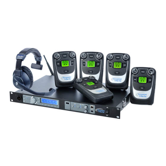
Clear-Com TEMPEST 2400 Reference Manual
Wireless intercom system
Hide thumbs
Also See for TEMPEST 2400:
- Reference manual (108 pages) ,
- User manual (16 pages) ,
- Quick start manual (4 pages)
Table of Contents
Advertisement
Quick Links
Advertisement
Table of Contents

Related Manuals for Clear-Com TEMPEST 2400


Summary of Contents for Clear-Com TEMPEST 2400
- Page 1 REFERENCE MANUAL ® TEMPEST 2400 WIRELESS INTERCOM SYSTEM...
- Page 2 No. 8 Yong An Dong Li Jian Guo Men Wai Ave Chao Yang District Beijing, P.R. China 100022 ® Clear-Com, CellCom/FreeSpeak and the Clear-Com Communication Systems logo are registered trademarks of The Vitec Group plc Website: www.clearcom.com Clear-Com Communication Systems...
-
Page 3: Table Of Contents
Table of Contents ............................. 3 Important Safety Instructions ......................... 8 A/C Power Warning ............................9 Thank you from Clear-Com .......................... 10 Thank you for choosing Tempest Wireless for your wireless intercom needs........10 Battery Safety ..............................11 Battery Transportation .......................... - Page 4 2- Talk Button and LED ..........................54 3- Call Button ............................54 4- Mic Kill Button ............................54 5- Local Headset Channel LEDs A-D ....................... 54 Clear-Com Communication Systems Page 4 of Tempest 2400 Wireless Intercom System...
- Page 5 Steps to Setup the Beltstations ........................ 66 Battery Selection and Installation ......................... 66 Charging the Lithium-Polymer Battery ......................67 Power Options ............................67 Beltstation Power On/Off .......................... 67 Clear-Com Communication Systems Page 5 of Tempest 2400 Wireless Intercom System...
- Page 6 Beltstation will not power up ........................81 Beltstation will not Pair with Base Station ....................81 Beltstation will not log into Base Station ....................81 Clear-Com Communication Systems Page 6 of Tempest 2400 Wireless Intercom System...
- Page 7 Tempest Remote Transceiver ........................82 Remote Transceiver RX or TX LEDs do not light ..................82 Tempest 2400 Wireless Intercom System Specifications ................84 Tempest 2400 Base Station Specifications ....................85 Tempest 2400 Beltstation Specifications ....................86 Tempest 2400 Remote Transceiver Specifications ..................
-
Page 8: Important Safety Instructions
Clear-Com Communication Systems Page 8 of 100 Tempest 2400 Wireless Intercom System... -
Page 9: A/C Power Warning
ALERT SYMBOL – Indicates important information. CAUTION SYMBOL – Indicates a potential to damage equipment. DANGER SYMBOL – indicates a potential safety hazard. Clear-Com Communication Systems Page 9 of 100 Tempest 2400 Wireless Intercom System... -
Page 10: Thank You From Clear-Com
Thank you from Clear-Com We at Clear-Com want to thank you for purchasing a Tempest 2400 Wireless Intercom System. We have made every effort to build a reliable, intuitive wireless intercom system that easily interfaces with your existing equipment, and provides the same functionality that you expect from your hard-wired intercom equipment. -
Page 11: Battery Safety
Your Tempest 2400 Wireless Intercom System includes rechargeable lithium-polymer batteries that power the beltstations. To insure that there is no violation of U.S or international laws, and to ensure your own safety, always: Transport rechargeable lithium batteries installed in the equipment they are intended to power. -
Page 12: Maintenance And Care
XLR connector on the bottom is not watertight. beltstations should not be submerged in liquids. Protect the battery compartment from water when changing batteries. The battery compartment offers a route to the electronic circuitry. Clear-Com Communication Systems Page 12 of 100 Tempest 2400 Wireless Intercom System... -
Page 13: Quick Start Guide
To power on the beltstation press and hold the power button for approximately 2 seconds. The display will indicate “None Selected”. Turn the power Off by holding the power button for four seconds. Clear-Com Communication Systems Page 13 of 100 Tempest 2400 Wireless Intercom System... -
Page 14: Pair Beltstations To The Base Station
Country limitation on 2.4GHz RF spectrum. See page 30 for details. • Adjusting the Network Number and Lockout Key on page 31. • Assigning names for equipment on page 32. • Charging batteries on page 67. Clear-Com Communication Systems Page 14 of 100 Tempest 2400 Wireless Intercom System... -
Page 15: General Description
General Description The Tempest 2400 Wireless Intercom System is a four-channel wireless intercom system that operates with up to five wireless beltstations per base station in full duplex simultaneous operation. Tempest operates in the non-licensed RF band at 2.4GHz. Tempest wireless systems will not interfere with traditional wireless microphone, IFB or in-ear monitor systems that operate in the UHF TV band. - Page 16 Tempest 2400 series base station comes standard with two RP-TNC RF antenna connectors and an RJ- 45 connector for remote RF transceiver operation. Antennas can be fixed directly to the back of the base station or remotely mounted using 50 ohm low loss RF cable from the RP-TNC connectors.
-
Page 17: Theory Of Operation
With 2xTX technology, each audio packet is transmitted twice, each on one of two consecutive hops. The loss of one packet transmission in a harsh RF environment is common. However, because of the quasi- Clear-Com Communication Systems Page 17 of 100 Tempest 2400 Wireless Intercom System... - Page 18 Tempest offers a host of features and technology to ensure that it performs well in almost all production environments virtually anywhere in the world with no licensing requirements or fees. Clear-Com Communication Systems Page 18 of 100 Tempest 2400 Wireless Intercom System...
-
Page 19: System Features
Battery Charger/Power Supply Remote Transceiver Remote Transceiver CAT-5 Cable for base station Connection - 15 Feet 2 X Whip Antenna ½ Wave Mounting Bracket Screws for Mounting Bracket (2) Clear-Com Communication Systems Page 19 of 100 Tempest 2400 Wireless Intercom System... -
Page 20: Other Items You May Need
3-PIN XLR cabling. This cabling is described under “2- Wire Wiring Schemes”. RJ-45 Connector Cable for 4-Wire If you plan to connect the Tempest base station to external Clear-Com 4-Wire intercom systems, you will need to provide the appropriate cabling. This is described under “4-Wire (Matrix) Intercom Interface”. -
Page 21: Stage Announce Xlr-3F Cable
3. Set Static or Dynamic Display – See page 32. 4. Name each base station and beltstation (optional, but encouraged) – See page 32. • Configure optional features Clear-Com Communication Systems Page 21 of 100 Tempest 2400 Wireless Intercom System... -
Page 22: Choose A Location
The Tempest base station should be in a location that has adequate ventilation and is not subject to extreme temperatures and humidity. Avoid areas subject to water or rain. Always use a stable and secure platform or rack mount system. Clear-Com Communication Systems Page 22 of 100 Tempest 2400 Wireless Intercom System... -
Page 23: Power Connections
MENU is pressed to escape or until the normal timeout is completed. The system will then display the main Operation screen and will be ready for normal use. Clear-Com Communication Systems Page 23 of 100 Tempest 2400 Wireless Intercom System... -
Page 24: Antenna Location
RF competition between systems and several other RF conditions. Judicious placement of antennas can help facilitate a large number of wireless beltstation users on a single system. Clear-Com Communication Systems Page 24 of 100 Tempest 2400 Wireless Intercom System... -
Page 25: Antenna Configuration
To remotely locate antennas always use high quality, low loss, 50 Ohm RF cable terminated with an RP- TNC connector for the base station side connection and the appropriate antenna mating connector on the Clear-Com Communication Systems Page 25 of 100 Tempest 2400 Wireless Intercom System... -
Page 26: Maximizing System Performance And Operational Range
Line-of-sight operation between the base station antennas and the beltstations will always produce the maximum system performance and operational range. Minimize obstructions between the base station antennas and the beltstations when possible. Clear-Com Communication Systems Page 26 of 100 Tempest 2400 Wireless Intercom System... - Page 27 RF signal into a smaller area. When the beltstation is located within this focused area of energy it will have a more powerful signal which will improve range. Only use approved antennas. Unauthorized antennas may be illegal. Clear-Com Communication Systems Page 27 of 100 Tempest 2400 Wireless Intercom System...
-
Page 28: Configure The Base Station
In Operational Mode a beltstation that is communicating with the base station will appear in a slot directly above a numbered button. Pressing one of the numbered buttons will advance directly to the “beltstation Settings” menu for that beltstation. Clear-Com Communication Systems Page 28 of 100 Tempest 2400 Wireless Intercom System... -
Page 29: Adjust Sidetone
There is a fraction of a second delay built into some functions of the buttons and knobs. It is possible to press buttons or turn knobs faster than they are permitted to react. Clear-Com Communication Systems Page 29 of 100 Tempest 2400 Wireless Intercom System... -
Page 30: Selecting A Frequency Band
Selecting a Frequency Band The Tempest 2400 Wireless Intercom System is approved for license free use in most countries. However, due to differences in radio spectrum regulations, some countries require that 2.4GHz equipment limit or adjust its RF spectrum operation. Always determine if there are country specific frequency restrictions that apply and select the required frequency band as described below. -
Page 31: Network Number And Lockout Key
Number”. Rotate the Volume control to adjust the value and press ENT to save. Press MENU to escape one level and select “Lockout Key”. Adjust the value and press ENT to save. Press MENU repeatedly to escape to the Operation screen. Clear-Com Communication Systems Page 31 of 100 Tempest 2400 Wireless Intercom System... -
Page 32: Set Display Mode To Static Or Dynamic
Press Enter to save the changes. beltstation names can be changed wirelessly from the base station’s menu or from T-Desk when the system is on a local area network. Clear-Com Communication Systems Page 32 of 100 Tempest 2400 Wireless Intercom System... -
Page 33: Base Station Headset Connection And Controls
This will help reduce unwanted echo in the system when that microphone is enabled. Clear-Com Communication Systems Page 33 of 100 Tempest 2400 Wireless Intercom System... -
Page 34: Front Panel Lock
On the beltstation a Call signal is sent only when the Talk button is enabled, and only on the channel(s) selected for Talk. Clear-Com Communication Systems Page 34 of 100 Tempest 2400 Wireless Intercom System... -
Page 35: Gpo Relay Contacts
Relay 2 Relay 2 Relay 3 Relay 3 Relay 4 Relay 4 Relay 5 Relay 5 Relay SA Relay SA Not Used Not Used Not Used Tempest DB-15 Connector Clear-Com Communication Systems Page 35 of 100 Tempest 2400 Wireless Intercom System... -
Page 36: Auxiliary Input/Output
Stage Announce screen. In addition the Stage button may be configured to also control an additional relay assigned to the users beltstation. See the GPO Relay section for more details. Clear-Com Communication Systems Page 36 of 100 Tempest 2400 Wireless Intercom System... -
Page 37: Reset Memory
Relay Key: Not selected Security: Disabled Select Relay: Not selected Frequency Band: 2400- SA: Disable 2480Mhz Display Slot Assignment: SA Relay: Enable Dynamic TCP/IP Mode: DHCP Security: Disabled Clear-Com Communication Systems Page 37 of 100 Tempest 2400 Wireless Intercom System... -
Page 38: Wired Intercom Interface To The Base Station
Channel A has been set for no wired intercom connection – the LEDs are off. • Channel B is set for Clear-Com 2-Wire intercom connection. The upper slide switch is in the middle position and the 2-Wire LED aligned with channel B is illuminated. -
Page 39: Controls
The two 2-Wire Intercom Type Select Switches determine the type of 2-Wire intercom that may be connected to the corresponding 2-Wire connectors on the rear panel of the base station. Clear-Com, RTS, or Balanced (AudioCom) can be selected. These switches only affect 2-Wire operation and do not control 4-Wire operation. The... -
Page 40: 4-Wire (Matrix) Intercom Interface
Tempest system. Tempest 4-Wire / RJ-45 Connection Pin # No Connection No Connection Audio Input (+) Audio Output (+) Audio Output(-) Audio Input (-) No Connection No Connection Clear-Com Communication Systems Page 40 of 100 Tempest 2400 Wireless Intercom System... -
Page 41: 2-Wire (Party-Line) Interface
• Null the system. For details see page 43. • Adjust IN/OUT volume levels between the Tempest 2400 Wireless Intercom System and the 2- Wire system. Always confirm that the 2-Wire intercom system is functioning properly before connecting the Tempest 2400 Wireless Intercom System. - Page 42 During Auto-Null, wired intercom users will hear the nulling tones and communication will be interrupted. It is recommended that this feature should be used only during setup and not during live events. Clear-Com Communication Systems Page 42 of 100 Tempest 2400 Wireless Intercom System...
-
Page 43: Auto-Null Procedure
Manual null requires each channel to be nulled individually. Return to the Null Screen and press SEL to advance to the next channel. Repeat for all channels. Clear-Com Communication Systems Page 43 of 100 Tempest 2400 Wireless Intercom System... -
Page 44: Other Causes Of Echo
If a user removes his headset, the Mic may detect and repeat the sound from the earpiece. Whenever a headset is removed, always turn off the Talk function. Clear-Com Communication Systems Page 44 of 100 Tempest 2400 Wireless Intercom System... -
Page 45: 2-Wire Wiring Schemes
4 intercom channels. The male and female connectors for each channel are loop-through connections and are the same point electrically. Each channel of a Clear-Com or Balanced 2-Wire system requires one separate cable for connection to one Tempest channel. -
Page 46: Connecting Multiple Base Stations
Configure each base station individually as described in 4-Wire (Matrix) Intercom Interface on page 40. The following information relates to multiple base station configurations without a matrix system. Clear-Com Communication Systems Page 46 of 100 Tempest 2400 Wireless Intercom System... -
Page 47: Steps To Configure A Multiple Base Station System
2-Wire intercom channel to be shared, to the base station that will use the intercom channel. Loop to other base stations as needed. Repeat for all channels to be shared. See the Wired Intercom Interface Clear-Com Communication Systems Page 47 of 100 Tempest 2400 Wireless Intercom System... - Page 48 When using an external 2-Wire hardwired connection, only channels that are connected to a wired intercom will be able to share audio between base stations. Clear-Com Communication Systems Page 48 of 100 Tempest 2400 Wireless Intercom System...
-
Page 49: Accu-Sync
The BaseSync cable is a DB-9F To DB-9M wired straight through on pins 1-5. Never connect Accu-Sync cables between 2.4GHZ and 900MHz Tempest models. BASESYNC IN Accu-Sync - DB-9 Connector Clear-Com Communication Systems Page 49 of 100 Tempest 2400 Wireless Intercom System... -
Page 50: Master Mode
If a slide switch is changed from Clear-Com to RTS or BAL, Master Mode will turn off, and it will be necessary to return to the “Multi-Base Setting”... -
Page 51: Special Rf Considerations With Multiple Base Stations
When two or more Tempest base stations are to be operated in the same location, connecting the base stations via the Accu-Sync connector on the back of the base station can significantly increase system performance and operational range. Clear-Com Communication Systems Page 51 of 100 Tempest 2400 Wireless Intercom System... -
Page 52: Multi-System Tempest Technology
FCC does not allow frequency hopping pattern synchronization as it would allow a single system or group of systems to monopolize the 2.4GHz ISM band. Clear-Com Communication Systems Page 52 of 100 Tempest 2400 Wireless Intercom System... - Page 53 The addition of one or more adverse conditions will limit the number, effectiveness and range of collocated systems in any given environment proportionally to the extent of the adverse condition(s). Clear-Com Communication Systems Page 53 of 100 Tempest 2400 Wireless Intercom System...
-
Page 54: Base Station Controls
Volume control while in Operational mode cycles the Channel LEDs in order from A thru D. 6- Peak LEDs The four Peak LEDs indicate when the mic audio from the local headset is reaching a peak level and is Clear-Com Communication Systems Page 54 of 100 Tempest 2400 Wireless Intercom System... -
Page 55: 7- Volume Control
WBP-1 and 2 are listening and talking on channel A, while also listening on channel D. • WBP-3 is utilizing the Stage Announce feature and has the Battery Alert turned off. • WBP-4 is listening on channels B and C. Clear-Com Communication Systems Page 55 of 100 Tempest 2400 Wireless Intercom System... -
Page 56: Front Panel Right
The two 2-Wire Intercom Type slide switches configure the base station for the type of intercom that will be connected to the corresponding 2-Wire connectors on the rear panel of the base station. Clear-Com, RTS, or Balanced (AudioCom) can be selected. This switch only affects 2-Wire operation and not 4-Wire operation. -
Page 57: 6- In Level Control
Always power cycle the beltstation after pairing. 10- Power ON/OFF Switch The ON/OFF switch is used to turn the base station power (AC or DC) on and off. Clear-Com Communication Systems Page 57 of 100 Tempest 2400 Wireless Intercom System... -
Page 58: Rear Panel Left
The RJ-45 4-Wire Intercom connectors (A/B/C/D) interface with 4-Wire intercom systems and devices including Clear-Com matrix systems. This is an intercom audio-only connector and does not support data transfer. The connector is balanced and transformer isolated. Nominal line level is -4 to +8 dBu. -
Page 59: 1- Sa (Stage Announce) Connector
The Tempest Remote Transceiver RJ-45 connector is used to connect the optional remote transceiver to the Tempest base station. The remote transceiver can be located up to 1,500 feet from the base station. Clear-Com Communication Systems Page 59 of 100 Tempest 2400 Wireless Intercom System... -
Page 60: Base Station Menu
Base Station Menu Clear-Com Communication Systems Page 60 of 100 Tempest 2400 Wireless Intercom System... - Page 61 Clear-Com Communication Systems Page 61 of 100 Tempest 2400 Wireless Intercom System...
-
Page 62: Remote Transceiver
Coaxial cable may be used to connect alternative antenna options. See the Antenna Configuration section on page 25. Pairs of Directional Antennas must be aimed to cover the same area Clear-Com Communication Systems Page 62 of 100 Tempest 2400 Wireless Intercom System... -
Page 63: Bottom View Of The Transceiver
Two Threaded Mounting Holes are provided on the back of the Remote Transceiver for use with the mounting bracket to mount the Transceiver in a convenient location. The mounting holes are #8-32 thread and accept a #8-32 x 3/8” pan head screw. Clear-Com Communication Systems Page 63 of 100 Tempest 2400 Wireless Intercom System... -
Page 64: Beltstation
Press MENU repeatedly to exit Menu Mode and return to Operational Mode. If no other items are selected Menu Mode will automatically exit after three minutes. Clear-Com Communication Systems Page 64 of 100 Tempest 2400 Wireless Intercom System... -
Page 65: Configure By The Pc Interface
60 of this manual. Configure by the PC Interface “T-Desk” software is available to manage your Tempest system. See the T-Desk Instruction manual for details. Clear-Com Communication Systems Page 65 of 100 Tempest 2400 Wireless Intercom System... -
Page 66: Beltstation Setup
Please be careful to insert alkaline AA batteries according to the marked polarity. All of the alkaline AA cells must be oriented the same direction. If the battery cover does not close properly, the battery may not be inserted correctly. Clear-Com Communication Systems Page 66 of 100 Tempest 2400 Wireless Intercom System... -
Page 67: Charging The Lithium-Polymer Battery
• Press and hold the Power ON/OFF button for 2 seconds to turn the beltstation on. • Press and hold for 4 seconds to turn the beltstation off. Clear-Com Communication Systems Page 67 of 100 Tempest 2400 Wireless Intercom System... -
Page 68: Pairing With A Base Station
In “Static” mode, if a beltstation is not turned on, or is logged out due to being out of range, the base station LCD will display a very obvious X, making it easy to see at a glance, which beltstations are Clear-Com Communication Systems Page 68 of 100 Tempest 2400 Wireless Intercom System... - Page 69 A Multiple base station system that uses iSelect Roaming must choose to use “Dynamic” slots to ensure that beltstations can move from base station to base station when roaming. Clear-Com Communication Systems Page 69 of 100 Tempest 2400 Wireless Intercom System...
-
Page 70: Name Equipment
A Call signal will be received by users who are listening on the channel that originates the Call signal. A call signal is sent only when the Talk button is enabled, only on the channel selected for Talk. Clear-Com Communication Systems Page 70 of 100 Tempest 2400 Wireless Intercom System... -
Page 71: Set Mic Gain
This will help reduce unwanted echo in the system when that microphone is enabled. Clear-Com Communication Systems Page 71 of 100 Tempest 2400 Wireless Intercom System... -
Page 72: Iselect Roaming - Selecting A Base Station
ENTER for the selected channel A or B. ENTER enables the headset mic regardless of the A/B Talk button. Wireless ISO only operates in Operational mode. It does not operate in Menu mode. Clear-Com Communication Systems Page 72 of 100 Tempest 2400 Wireless Intercom System... -
Page 73: Beltstation Overview
Talk enabled. The Call signal will be routed to intercom channels indicated by the user’s active Talk button(s). Clear-Com Communication Systems Page 73 of 100 Tempest 2400 Wireless Intercom System... -
Page 74: 1- Rubberized Access Cover
The 4-PIN XLR male headset connector mates with most Dynamic or Electret headsets that have 4-PIN XLR female connectors. This Headset connector allows a user to communicate on up to two of the four intercom channels. Clear-Com Communication Systems Page 74 of 100 Tempest 2400 Wireless Intercom System... -
Page 75: Talk Button A/B And C/D
Talk is enabled on that channel. The Channel Indicator LEDs will flash red when the microphone signal is reaching a peak level and is entering into limiting. Clear-Com Communication Systems Page 75 of 100 Tempest 2400 Wireless Intercom System... -
Page 76: Beltstation Menu
Beltstation Menu Clear-Com Communication Systems Page 76 of 100 Tempest 2400 Wireless Intercom System... -
Page 77: How Do I
To select, press ENT, or press the CH A/B knob. If no entry is made within a few seconds, the display will automatically return to the Operation Screen. Clear-Com Communication Systems Page 77 of 100 Tempest 2400 Wireless Intercom System... -
Page 78: Adjust Min/Max Beltstation Volume Levels
Stage Announce Relay is enabled, all three functions will operate simultaneously. If ENTER is selected to activate the relay, and if Wireless ISO is enabled, both functions will Clear-Com Communication Systems Page 78 of 100 Tempest 2400 Wireless Intercom System... -
Page 79: From The Base Station
Adjust the IN and OUT level for the appropriate intercom channel to achieve the desired audio levels. Ensure that all external 2-Wire or 4-Wire hardwired intercom connections have been properly made on Clear-Com Communication Systems Page 79 of 100 Tempest 2400 Wireless Intercom System... -
Page 80: Headset Microphone Sounds Distorted Or Cuts Off Parts Of Words
Select 2-Wire for the relevant channels. Set only one of the Tempest base stations to Master Mode. Audio can only be passed from one base station to another in the “Clear-Com mode” unless actually connected to another type of intercom system. -
Page 81: Beltstation
The button may have been reassigned wirelessly from the base station or by T- Desk. Confirm that the function is available for use. If the reassignment involves any GPO, confirm that menu selection, the connections, and the equipment functionality. Clear-Com Communication Systems Page 81 of 100 Tempest 2400 Wireless Intercom System... -
Page 82: Call Function
Beltstations can access all 4 intercom channels and “Dual-Listen” to 2 of the 4 channels Weather resistant beltstations Beltstations can send and receive “Call Alert” signal from wired intercom systems Clear-Com Communication Systems Page 82 of 100 Tempest 2400 Wireless Intercom System... - Page 83 Auxiliary audio input and output LAN control interface Electret or Dynamic Mic auto select Multiple Antenna connection options Compatible with Clear-Com®, RTS®, Telex®, and other 2-Wire and 4-Wire intercom systems Clear-Com Communication Systems Page 83 of 100 Tempest 2400 Wireless Intercom System...
-
Page 84: Tempest 2400 Wireless Intercom System Specifications
Tempest 2400 Wireless Intercom System Specifications RF Frequency 2400 to 2480 RF Scheme FHSS with TDMA Effective Radiated Power 100mW using 2dBi antenna 5 − Receiver Sensitivity -93 dBm for 10 Radio Certification FCC Part 15.247 and ETS 300.328 rules, license free... -
Page 85: Tempest 2400 Base Station Specifications
Tempest 2400 Base Station Specifications Intercom Audio Channels Full Duplex beltstations per base station Half-Duplex, Shared beltstations per base station Number of Antenna Ports per base station Antenna Connector Type RP-TNC Number of Synchronized base stations Base station/beltstation pairing Via supplied Mini-jack/cable... -
Page 86: Tempest 2400 Beltstation Specifications
° Operating Environment to 50° C (-4 to 122 10% to 90% Humidity Tempest 2400 Remote Transceiver Specifications Maximum Distance, Base to Transceiver 1,500 ft., powered from the base station Connection to base station CAT-5 standard wiring Base stations Supported per Transceiver... -
Page 87: Fcc Information
To ensure compliance with FCC exposure limits, no person must come closer than 26 cm (ten inches) from either the standard 4” Rubber Whip Antenna, the optional Directional Corner Reflector Antenna, or other approved antenna whichever is used with the Tempest base station. Clear-Com Communication Systems Page 87 of 100 Tempest 2400 Wireless Intercom System... -
Page 88: Tempest 2400 System Block Diagram
Tempest 2400 System Block Diagram Clear-Com Communication Systems Page 88 of 100 Tempest 2400 Wireless Intercom System... -
Page 89: Tempest Block Diagram Continued
Tempest Block Diagram Continued Clear-Com Communication Systems Page 89 of 100 Tempest 2400 Wireless Intercom System... -
Page 90: Tempest Part Numbers
RJ45 Ethernet cable 15 foot in length USB A to USB B cable 6 foot length 1/8" to 1/8" stereo mini pairing cable 6 foot in length Tempest® beltstation battery cover Clear-Com Communication Systems Page 90 of 100 Tempest 2400 Wireless Intercom System... -
Page 91: Glossary
IFB: Interrupted Feedback, or Interrupted Fold-Back - The IFB system connects control room personnel such as the director, or producer with the performers or “talent”. The performer wears a small earpiece that carries Clear-Com Communication Systems Page 91 of 100 Tempest 2400 Wireless Intercom System... - Page 92 Tempest Remote Transceiver: An accessory used with the Tempest base station to locate the antennas apart from the base station without RF signal loss or attenuation. USB-A: USB-B: USB mini-B: Clear-Com Communication Systems Page 92 of 100 Tempest 2400 Wireless Intercom System...
-
Page 93: Limited Warranty
(1) Cables, accessories, components & consumable items have a Limited Warranty of 90 days. (2) Any Clear-Com product that has been classified as obsolete at the time of sale has a Limited Warranty of 90 days from sales and will be replaced with the same product or a sales credit will be issued, at the sole discretion of Clear-Com. - Page 94 Clear-Com determines is not a result of failure in the Services provided by Clear-Com. Further Services excluded from this Agreement include: services required due to errors or omissions in Customer purchase orders;...
- Page 95 Agreement. Clear-Com Communication Systems Page 95 of 100 Tempest 2400 Wireless Intercom System...
-
Page 96: Technical Support & Repair Policy
Email: CustomerServicesAPAC@vitecgroup.com Email Technical Support is available for all Clear-Com branded products free of charge for the life of the product, or two years after a product has been classified as obsolete, whichever comes first. Support for Distributor and Dealer Sales Distributors and Dealers may utilize the Customer Service Centers once a system has been installed and commissioned. - Page 97 The Customer will be provided with an RMA number upon contacting Clear-Com Sales Support as instructed below. The RMA number must be obtained from Clear-Com via phone or email prior to returning product to the Service Center. Product received by the Service Center without a proper RMA number is subject to return to the Customer at the Customer’s expense.
- Page 98 Customers requesting a non-warranty repair will be provided an estimate of the total repair cost prior to the return of the equipment. In the event that Clear-Com is unable to estimate the cost of repair, the Customer may elect to return the product to the factory for an estimate. The Customer is responsible for shipping costs both to and from the factory in the event they choose not to accept the estimate.
- Page 99 Note: Clear-Com’s Limited Warranty does not cover normal wear and tear. The Customer will be charged the full cost of the repair if their equipment has been tampered with by non-approved personnel, or has been subject to damage through electrical failure, liquid damage or mishandling.
-
Page 100: Index
Stage ..............72 Stage Announce ........... 35, 58 Headset .............. 32 Talk ............... 53, 74 Headset Connector ..........53 HEADSETS ............20 Wireless ISO ............71 IN ..............56, 58 Clear-Com Communication Systems Page 100 of 100 Tempest 2400 Wireless Intercom System...
Need help?
Do you have a question about the TEMPEST 2400 and is the answer not in the manual?
Questions and answers