
Subscribe to Our Youtube Channel
Related Manuals for Clear-Com Eclipse HX-PiCo


Summary of Contents for Clear-Com Eclipse HX-PiCo
- Page 1 User Guide Eclipse ® HX-PiCo User Guide for the HX-PiCo matrix Part Number: 399G145 Rev B Date: 03/June/15...
- Page 2 Legal Disclaimers Copyright © 2015 HME Clear-Com Ltd. All rights reserved. Clear-Com and the Clear-Com logo are trademarks or registered trademarks of HM Electronics, Inc. The software described in this document is furnished under a license agreement and may be used only in accordance with the terms of the agreement.
-
Page 3: Table Of Contents
Level control ................14 Power supplies ..............14 Rear panel connectors (Ports) ..........14 Eclipse HX-PiCo front panel controls and lights ......15 4 Connecting to external devices ............. 19 4.1 Intelligent linking between Eclipse HX matrix frames (matrices) ..19 ... - Page 4 Adjusting audio levels ..............48 6.4 Creating audio routes ..............51 6.5 Selecting and activating a configuration map .........52 6.6 Setting the IP address for the Eclipse HX-PiCo ........53 6.7 Accessing system information ............55 6.8 Accessing system status .............56 6.9 Selecting a source of Identification Tone ........57 ...
- Page 5 User Guide | Eclipse HX-PiCo 8.8 Notice about Specifications ............68 8.9 Menu Map for the Eclipse HX-PiCo ..........69 9 Glossary ..................70 10 Compliance ................75 Page 5...
-
Page 6: Important Safety Instructions
User Guide | Eclipse HX-PiCo Important Safety Instructions Read these instructions. Keep these instructions. Heed all warnings. Follow all instructions. Do not use this apparatus near water. Clean only with dry cloth. Do not block any ventilation openings. Install in accordance with the manufacturer’s instructions. - Page 7 User Guide | Eclipse HX-PiCo fallen into the apparatus, the apparatus has been exposed to rain or moisture, does not operate normally, or has been dropped. Warning: To reduce the risk of fire or electric shock, do not expose this product to rain or moisture.
-
Page 8: Safety Symbols
User Guide | Eclipse HX-PiCo Safety symbols Familiarize yourself with the safety symbols in Figure 1. These symbols are displayed on the apparatus and warn you of the potential danger of electric shock if the system is used improperly. They also refer you to important operating and maintenance instructions in the product user manual. -
Page 9: Introduction
At the heart of the system is the central matrix, comprising a matrix frame and the highly intuitive EHX configuration software, run from an external PC. The Eclipse HX-PiCo User Guide describes how to use the most compact matrix frame in the Eclipse HX product range, the 1RU Eclipse HX-PiCo. -
Page 10: S Ummary Of Chapters
/ documentation for that device or software. Eclipse HX documentation is available from: Your product DVD-ROM. The Clear-Com website (http://www.clearcom.com/product/digital-matrix). For sales information, see your Clear-Com sales representative. For contact information, see Page 2 of this guide. Page 10... -
Page 11: Overview
User Guide | Eclipse HX-PiCo Overview This chapter provides an overview of the Eclipse HX-PiCo, including its applications, functionality, power supplies and connectors. Eclipse HX matrix frames There are four matrix frames in the HX product range: Matrix frame (matrix) -
Page 12: Eclipse Hx-Pico Matrix Frame
EHX configuration software. Chassis and assembly The Eclipse HX-PiCo matrix frame is 19 inches wide and one rack unit (1RU) high (26.9 cm x 48.3 cm). It installs to a standard Electronics Industry Association equipment rack. -
Page 13: Applications Of The Eclipse Hx-Pico
Frequency response of 30 Hz - 22 kHz, ± 3 dB. SNR (Signal-to-Noise Ratio) and crosstalk > -70 dB. Note: The Eclipse HX-PiCo matrix frame supports the same V-Series and i-Series user panels, interface cards and interface modules as its larger counterparts, the Eclipse HX-Omega and the Eclipse HX-Median matrices. -
Page 14: Level Control
User Guide | Eclipse HX-PiCo Level control You can connect the Eclipse HX-PiCo to a wide range of user panels and other intercom devices either directly or through the interface cards and modules (fitted to other system or interface frames). -
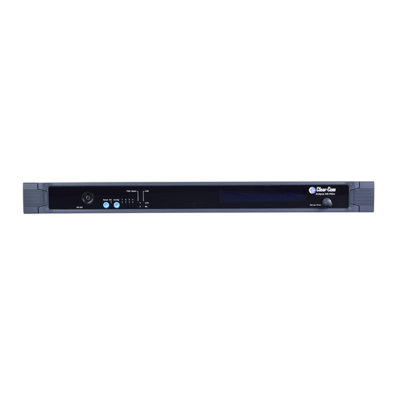
Page 15: Eclipse Hx-Pico Front Panel Controls And Lights
User Guide| Eclipse® HX-PiCo Eclipse HX-PiCo front panel controls and lights Figure 2: Front panel controls and lights Page 15... - Page 16 OK light (LED) When flashing once per second (1:1 1Hz), the OK light indicates that the Eclipse HX-PiCo matrix is running normally. Configuration ( CONFIG ) button The Eclipse HX-PiCo can hold four complete system configurations in its operational memory. Any one of the four configurations can be activated using the CONFIG button on the matrix front panel.
- Page 17 Power supply alarm lights (1 and 2) An Eclipse HX-PiCo matrix has two internal power supply units. One power supply unit can power an entire matrix; the second unit provides a backup in case of an equipment failure.
- Page 18 PiCo matrix, without recourse to the EHX configuration software (hosted on an external PC). For more information about using the Eclipse HX-PiCo menu system, see 6 Using the Eclipse HX-PiCo. Table 3: Key to Figure 2: Front Panel controls and lights...
-
Page 19: Connecting To External Devices
Intelligent linking between Eclipse HX matrix frames (matrices) You can use intelligent linking to connect an Eclipse HX-PiCo to an Eclipse HX- Median, Eclipse HX-Omega, Eclipse HX-Delta and other Eclipse HX-PiCo matrices. Up to 15 matrices may be connected. The linking between matrices is achieved using dedicated trunk lines between ports on the linked systems. -
Page 20: Linking To User Panels (V-Series And I-Series Panels)
To find out more about installing, using, maintaining and connecting user panels to the Eclipse HX-PiCo, see the appropriate product manual / guide. Linking to interface modules Interface modules convert the four-wire signals of a central matrix port to other types of signals that communicate with devices such as telephones, camera intercoms, two-way radios, and so on. -
Page 21: Ehx Configuration Software
The Eclipse HX configuration software (EHX) controls the operation of the connected devices (such as user panels, interface modules and interface frames) by sending signals to the CPU in the Eclipse HX-PiCo, which then relays the signals to the devices. -
Page 22: Installing The Eclipse Hx-Pico
User Guide | Eclipse HX-PiCo Installing the Eclipse HX-PiCo This chapter describes how to install the Eclipse HX-PiCo matrix frame to a standard 19” (48.26 cm) rack. It also shows you how to connect the matrix to the mains power supply and external devices, including other matrix frames (matrices) and user panels. -
Page 23: Powering The Eclipse Hx-Pico
(see section below). Note: The Eclipse HX-PiCo requires 100 - 240 VAC at 50 - 60 Hz. The maximum input power to each of the two power supplies is 60 watts. For the power supply specifications, see 8.7 Power supply unit. -
Page 24: Rear Panel Connectors
User Guide | Eclipse HX-PiCo Rear panel connectors Figure 3: Rear panel connectors Page 24... -
Page 25: Connecting User Panels And Interface Modules
Table 4: Key to Figure 4: Rear panel connectors Connecting user panels and interface modules An Eclipse HX-PiCo rear panel contains 36 RJ-45 sockets for connecting the matrix to remote user panels (V-Series and I-Series user panels), interface modules and other intercom devices. -
Page 26: Dual Tone Multi Frequency (Dtmf) Generation And Detection
DTMF generation and detection is only supported on 16 ports (ports 17 – 32) on the Eclipse HX-PiCo. When using a TEL-14 interface module with the Eclipse HX- PiCo, Clear-Com recommends that the TEL-14 is connected to one of these matrix ports for full functionality. -
Page 27: 2-Pair Analog
Figure 4: Connecting the matrix frame to an analog panel (4-Pair connection) 2-Pair analog Eclipse HX-PiCo uses a 2-pair analog wiring scheme between the matrix and four- wire equipment. Note: The wiring scheme shown in Figure 5 below is for four-wire equipment with an RJ- 45 connector. - Page 28 User Guide | Eclipse HX-PiCo Pair Description Pair 1 Pair 1 is not used. Pair 2 Transmits digital data from the four-wire device back to the matrix Pair 3 Transmits audio from the four-wire device to the matrix. Pair 4 Pair 4 is not used.
-
Page 29: Single-Pair Digital
Figure 6: Connecting the matrix frame to a digital panel (single-pair digital) Connections using general-purpose outputs (GPO’s) The male 25-pin D-type socket labeled GP OUT allows the Eclipse HX-PiCo matrix to be connected to eight general purpose outputs (GPOs). General-purpose outputs are single-pole double-throw relays with contact ratings of 30 VDC (volts direct current) at 1 Ampere. - Page 30 Each general-purpose output has a relay inside the Eclipse HX-PiCo matrix. When a general-purpose output is inactive, the associated common pin on the GP OUT connector will be shorted to the relevant normally closed pin.
- Page 31 User Guide | Eclipse HX-PiCo DB-25M connector Common Common Normally closed RELAY1 RELAY5 Normally closed Normally open Normally open Common Common Normally closed RELAY2 RELAY6 Normally closed Normally open Normally open Common Common Normally closed RELAY3 RELAY7 Normally closed Normally open Normally open Common Common Normally closed RELAY4 RELAY8 Normally closed Normally open Normally open Digital ground Figure 7: Pin configuration of the GPO connector (DB-25M)
-
Page 32: Connections Using General-Purpose Inputs (Gpi's)
User Guide | Eclipse HX-PiCo Pin 6 Normally open RELAY2 Pin 7 Common Pin 8 Normally closed RELAY3 Pin 9 Normally open Pin 10 Common Pin 11 Normally closed RELAY4 Pin 12 Normally open Pin 13 Digital ground Pin 14... - Page 33 To operate the Eclipse HX-PiCo matrix in opto-isolated mode If the Eclipse HX-PiCo unit is connected to AC power, disconnect it from AC power. Remove the top cover of the Eclipse HX-PiCo matrix by unscrewing the 12 M3 x 6 flat screws and lifting the cover upwards.
- Page 34 Figure 9: Opto-Isolated connection to Eclipse HX-PiCo GPI connector In this mode, a DC voltage of between 7 - 24 V is required at the EXTVIN+ pin with relation to the EXTVIN–...
- Page 35 User Guide | Eclipse HX-PiCo DB-25F connector Logic input 1 Logic input 5 Logic input 2 Logic input 6 Logic input 3 Logic input 7 Logic input 4 Logic input 8 Ground V IN + Ground V IN + Ground V IN - Ground V IN - Ground Figure 10: Pin connection General Purpose Inputs, DB-25F connector DB-25F Connector Description Pin 1 Logic input 1...
-
Page 36: Connecting To A Gpi/Rly Interface
Table 8: Pin connection General Purpose Inputs, DB-25F connector Connecting to a GPI/RLY Interface The RJ-45 connector labeled GPI/RLY Interface connects the Eclipse HX-PiCo matrix to a GPI-6 or RLY-6 interface card. The GPI-6 provides six general- purpose opto-isolated logic inputs. The RLY-6 module provides six single-pole, double-throw relay outputs. - Page 37 User Guide | Eclipse HX-PiCo To connect a RLY-6 interface that has been housed in an IMF-3 interface module frame to the matrix: 1. Connect one end of an RJ-45 cable (eight wires with no reversal) to the GPI/RLY INTERFACE connector on the back of the matrix.
- Page 38 User Guide | Eclipse HX-PiCo Figure 11: RLY-6/GPI-6Daisy Chain Connection Connecting external devices to the RLY-6 interface module To connect external devices to the RLY-6 interface module in an IMF-3 interface module frame, use the two DB-9M connectors on the rear cable assembly panel for the interface.
- Page 39 User Guide | Eclipse HX-PiCo In Figure 12: RLY-6 DB-9M connector pinout, the labels on the pins apply to either connector. For example, #1/4 COM refers to the wiper of relay 1 if it is connected to CH. A, and the wiper of relay 4 if it is connected to CH. B.
- Page 40 User Guide | Eclipse HX-PiCo #2/5 Normally closed #2/5 Normally open #3/6 COM Table 9: Key to Figure 13: RLY-6 DB-9M connector pinout RLY-6 interface module in an IMF-102 interface frame Connecting to a RLY-6 interface module in an IMF-102 interface frame is the same as connecting to a RLY-6 interface module in an IMF-3 interface frame.
- Page 41 User Guide | Eclipse HX-PiCo Connect the other end into the top RJ-45 (CH. A MATRIX) connector for the additional GPI-6. Additional GPI-6 interface modules are added in the same way, using daisy-chain wiring. If there are multiple GPI-6 modules, the inputs in the first interface are numbered 1 to 6 for GPI 1;...
- Page 42 User Guide | Eclipse HX-PiCo Key to Figure 13: GPI-6 DB-9M connector pinout Connector Description #1/4 Input A #2/5 Input A #3/6 Input A Ground Ground #1/4 Input B #2/5 Input B #3/6 Input B Power source Table 10: Key to Figure 13: GPI-6 DB-9M connector pinout...
- Page 43 User Guide | Eclipse HX-PiCo Figure 14 shows how to connect switches or contacts using the power source provided by the GPI-6 module or powering switches from external sources. Each input can be wired to be isolated from each other as a further variation.
-
Page 44: Connecting To Another Eclipse Hx-Pico (Pico-Link)
Pin 7 Table 11: CAT-5 crossover cable pinout To transfer data between two linked Eclipse HX-PiCo matrices using the PiCo-Link also requires that the Ethernet ports are connected with either a cross-over shielded CAT-5 cable or a hub or switch using conventional shielded CAT-5 cable. -
Page 45: Connecting To An External Pc Running Ehx
User Guide | Eclipse HX-PiCo Figure 15: Standard pin assignments for a LAN connector Note: If the LAN connector is used a ferrite core must be added to the socket end of each cable. A suitable ferrite is Würth Electronik part: 74271132. A shielded CAT-5 cable should be used. -
Page 46: Serial Connection To The Pc
User Guide | Eclipse HX-PiCo Serial connection to the PC A DB-9F connector is used at the PC, when wiring for an Eclipse HX-PiCo serial connection. The 3.5mm jack socket is labeled RS-232 on the front of an Eclipse HX-PiCo. Ensure that: ... -
Page 47: Using The Eclipse Hx-Pico
Note: For the location of the display screen and the Setup / enter rotary control, see Figure 2: Front panel controls and lights. The Eclipse HX-PiCo display dims when the unit has not been used for three minutes. Pressing any key causes the previously displayed screen to reappear. -
Page 48: Adjusting Audio Levels
Figure 18: System Ports menu display Note: A port connection represents one of the RJ-45 connectors on the rear panel of the Eclipse HX-PiCo to which remote panels and / or interfaces have been connected with shielded CAT-5 cable. When an external device is connected to a port, the rectangle for that port first... - Page 49 User Guide | Eclipse HX-PiCo Figure 19: Audio menu display From the Audio menu, select either: INPUTS. From the Input Level menu the incoming volume level to a port can be adjusted. OUTPUTS. From the Output Level menu the outgoing volume level from a port can be adjusted.
- Page 50 User Guide | Eclipse HX-PiCo Note: The audio level changes in real time as the setup/enter rotary control is rotated in the same way as adjusting the audio with a volume control. d) When the desired decibel level appears in the display, press the Setup/Enter rotary control to select and save it.
-
Page 51: Creating Audio Routes
Creating audio routes An audio route between a source and a destination can quickly and easily be created directly from the Eclipse HX-PiCo’s front panel. To create an audio route: From the Main menu, select Routing. The Routes menu is displayed. -
Page 52: Selecting And Activating A Configuration Map
2. To confirm the route, scroll to and select Yes. To back out from the changes select either No or Exit. Selecting and activating a configuration map Each Eclipse HX-PiCo matrix can store up to four complete configuration maps in its onboard memory. For more information about EHX, see also 4.2 EHX configuration software. -
Page 53: Setting The Ip Address For The Eclipse Hx-Pico
Apply Labels menu in EHX. For more information, see your EHX documentation. Setting the IP address for the Eclipse HX-PiCo The factory default for the Eclipse HX-PiCo IP address is DHCP enabled. When a DHCP server is located, and an IP address is allocated, then the Eclipse HX- PiCo’s IP address can be viewed using the menu system. - Page 54 User Guide | Eclipse HX-PiCo Note: If a DHCP server cannot be located on power up, then the Eclipse HX-PiCo uses the link local (system default) IP address (169.254.0.100). If the PC running the EHX software is also DHCP enabled, and is also unable to locate a DHCP server, then the matrix and the PC can communicate on the link local network address.
-
Page 55: Accessing System Information
Accessing system information Information about the system number and firmware version can be accessed directly from the front panel menus of the Eclipse HX-PiCo. To access the system number or firmware version: From the Main menu, select System. The System menu is displayed. -
Page 56: Accessing System Status
User Guide | Eclipse HX-PiCo Figure 24: System Information display System Number shows the system number for the Eclipse HX-PiCo (even if multiple Eclipse HX-PiCos are linked over a network). Firmware Version shows the currently active firmware version for the Eclipse HX- PiCo. -
Page 57: Selecting A Source Of Identification Tone
This field shows the status of any data download from a connected PC computer operating the EHX software. When data downloads to the Eclipse HX-PiCo matrix from a connected PC, either Serial Download or Ethernet Download is displayed to indicate the type of download. -
Page 58: 6.10 Resetting The System
6.10 Resetting the system Resetting the system restores the currently selected configuration map, while restoring active calls and activating any changes made from the Eclipse HX-PiCo’s front panel since the last reset. Another type of reset restores the currently selected configuration map, while clearing active calls and clearing any changes made from the Eclipse HX-PiCo’s... -
Page 59: Checking The Status Of General Purpose Inputs (Gpis)
(GPI’s) Once a GPI has been connected, you can check the on / off status of the GPI directly from the front panel of the Eclipse HX-PiCo. To check whether or not a general-purpose input is on: From the Main menu, select Status. The Status menu is displayed. -
Page 60: Checking The Status Of General Purpose Outputs (Gpos)
After a GPO has been connected it is possible to check whether or not a GPO is on directly from the front panel of the Eclipse HX-PiCo. A GPO can be toggled on or off directly from the Eclipse HX-PiCo front panel as well. - Page 61 User Guide | Eclipse HX-PiCo Figure 28: GPO Status menu display If a GPO is on an X appears in the checkbox next to that GPO number on the menu. An unchecked box indicates that a GPO is off. To toggle a GPO on, scroll to and select its associated checkbox. To toggle a GPO off, clear its associated checkbox.
-
Page 62: Maintaining The Eclipse Hx-Pico
Dual independent power supplies The Eclipse HX-PiCo matrix includes two internal power supply units. One power supply unit can power an entire matrix; the second unit provides a backup in case of an equipment failure. -
Page 63: Specifications
User Guide | Eclipse HX-PiCo Specifications General Note: 0 dBu is referenced to 0.775 Volts RMS. Specification Description / Value 44mm (1.75inches) (1RU) Height 482mm (19 inches) Width 300 mm (12 inches) Depth 5 kg max Weight 60 W Max per inlet... -
Page 64: Matrix Frame Performance
User Guide | Eclipse HX-PiCo Matrix frame performance Specification Description / Value 48 kHz Sample Rate 24 bit Resolution 30 Hz – 22 kHz ± 3 dBu Frequency Response @ 48 kHz sampling <–70 dBu Crosstalk (adjacent channel) 0 dBu... -
Page 65: Matrix Frame Interfaces
User Guide | Eclipse HX-PiCo Matrix frame interfaces Specification Description / Value 8 total, opto-isolated GPI inputs 8 total, isolated relay contacts GPI outputs 25-pin D-Type socket on rear panel GPI connector 25-pin D-Type socket on rear panel GPO connector... -
Page 66: Minimum Pc Requirements (For Ehx Software)
User Guide | Eclipse HX-PiCo Table 22: System resolution Minimum PC requirements (for EHX software) Specification Description / Value 1 GHz Processor 1GB RAM Memory 1GB minimum 32 bit, 2GB minimum 64 bit. Hard disk CD-ROM drive Input devices SVGA... -
Page 67: Recommended Pc Requirements (For Ehx Software)
User Guide | Eclipse HX-PiCo Recommended PC requirements (for EHX software) Specification Description / Value 2GHz or greater for a client. Processor As many cores as possible for a server. 2GB for client 32 bit. Memory 4GB for client 64 bit. -
Page 68: Notice About Specifications
Table 25: Recommended PC requirements Notice about Specifications While Clear-Com makes every attempt to maintain the accuracy of the information contained in its product manuals, that information is subject to change without notice. Performance specifications included in this manual are design-center specifications and are included for customer guidance and to facilitate system installation. -
Page 69: Menu Map For The Eclipse Hx-Pico
User Guide| Eclipse® HX-PiCo Menu Map for the Eclipse HX-PiCo Note: The following menu map does not include screens for confirmation and reboot, which are displayed automatically after some screens. Figure 29: Eclipse HX-PiCo menu map Page 69... -
Page 70: Glossary
User Guide| Eclipse® HX-PiCo Glossary Term Definition Any of the Eclipse HX matrix’s analog input/output RJ- 45 connectors that are used to connect cable from the Analog Port matrix to panels and interfaces. Each port connects to a separate audio channel in the matrix. - Page 71 User Guide | Eclipse® HX-PiCo Central matrix The term central matrix is used to differentiate the central hardware and software of the intercom system from the connected audio devices. The central matrix consists of: The metal housing for the circuit cards and power supplies.
- Page 72 User Guide | Eclipse® HX-PiCo Interruptible Foldback. The term foldback refers to sending program audio / feed, or some other audio mix, back to announcers while they are on the air. Doing so allows announcers to monitor themselves, other announcers, videotapes of commercials, or some mix of sources, while they on the air.
- Page 73 User Guide | Eclipse® HX-PiCo Label A label is an alphanumeric name of up to five characters that identifies a source, destination, or control function accessed by an intercom panel. Labels appear in the displays of the intercom panel. Labels can identify panels, ports interfaced to other external equipment, fixed groups, party lines, and special control functions.
- Page 74 User Guide | Eclipse® HX-PiCo Partyline A wired shared communication system based on a single screened pair of wires. See the Encore range. Matrix requires the CCI-22 to interface to it. Port Any of the input/output connections (RJ-45 connectors) on the back panel of the central matrix. These connectors and the attached cables connect the central matrix to remote intercom devices.
-
Page 75: Compliance
User Guide | Eclipse® HX-PiCo Compliance CE/FCC Conformity This document confirms that this product bearing the CE (Communauté Européenne) label meets all requirements in the EMC directive 2004/108/EG laid down by the Member States Council for adjustment of legal requirements. Furthermore the product complies with the rules and regulations of the low- voltage directive 2006/95/EG and the Restriction of Hazardous Substances Recast Directive 2011/65/EU (RoHS 2). - Page 76 User Guide | Eclipse® HX-PiCo Industry Canada Compliance Statement This Class B digital apparatus complies with Canadian ICES-003. Avis de conformité à la réglementation d'Industrie Canada Cet appareil numérique de la classe B est conforme à la norme NMB-003 du Canada.
Need help?
Do you have a question about the Eclipse HX-PiCo and is the answer not in the manual?
Questions and answers