
Subscribe to Our Youtube Channel
Related Manuals for HBM RM4220


Summary of Contents for HBM RM4220
- Page 1 Operating Manual Bedienungsanleitung S.G.‐Amplifier DMS‐Verstärker RM4220 A1091-4.0 en/de...
- Page 2 English ..........Seite 3 - 20 Deutsch .
-
Page 3: Table Of Contents
RM4220 Contents Page English Safety instructions .......... -
Page 4: Safety Instructions
The same applies to the use of accessories. The scope of supply and performance of the RM4220 covers only a small area of measurement technology. In addition, equipment planners, installers and operators should plan, implement and respond to the safety engineering con... - Page 5 The same applies to the use of accessories. General dangers of failing to follow the safety instructions The RM4220 amplifier corresponds to the state of the art and is failsafe. The device may give rise to residual dangers if it is inappropriately installed and operated by untrained personnel.
-
Page 6: Markings Used
CE mark The CE mark enables the manufacturer to guarantee that the product complies with the requirements of the relevant EC directives (the Declaration of Con formity can be found on the HBM website at www.hbm.com under Support -> HBMdoc). - Page 7 RM4220 The markings used in this document The marking below draws your attention to important information about the product or about handling the product. Important Important information A1091-4.0 en/de...
-
Page 8: Application
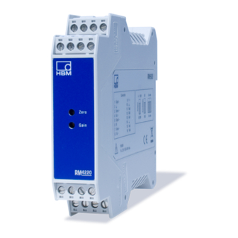
RM4220 Application The RM4220 module is an amplifier for sensors with strain gages. The ampli fier offers a very simple and practical setting of the zero point and the full scale with DIP switches and potentiometers. The bridge excitation voltage can be selected: 5 or 10 V. -
Page 9: Mounting/Dismounting
The support rail must be connected to grounded conductor potential . This means that the RM4220 ground connection ( ) is also connected to the groun ded conductor potential. The surrounding housing must also be grounded, i.e. connected to the grounded conductor potential. -
Page 10: Electrical Connection
The shielding must be connected extensively. With other connection tech niques, an EMC‐proof shield should be applied in the wire area and this shield should also be connected extensively (see also HBM Greenline Information, brochure i1577). The surrounding housing must be EMC‐proof. All cables that lead into this housing must be shielded and/or equipped with filters. - Page 11 GND, preferable for current output Connection with six‐wire configuration (see Section 5.2, Page 13) Terminal Function Color of transducer connection (HBM cable with six‐wire configuration) Signal -: Measurement signal (‐) RD (red) Cable shield / Drain wire Sense +: Sense lead (+) GN (green) Exc +: Excitation voltage (+) for trans...
-
Page 12: Configuration And Balancing (Adjustment)
RM4220 Configuration and balancing (adjustment) Requirements for setup: • The housing is open • The transducer is connected • The supply voltage is connected and switched on Important Switch the device on 15 minutes before adjustment to obtain a precise adjust... -
Page 13: Setting The Dip Switches
RM4220 ZERO GAIN Output voltage (0 … 10 V) Excitation voltage (10 V) Four‐wire or six‐wire configuration (four‐wire) Resistors for filter (SMD) Resistors for filter (conventional technology) Fig. 5.2: Motherboard and position of DIP switch with opened housing, factory set... -
Page 14: Set Amplification
RM4220 @ 1000 Bridge Null (mV V) + " 4 @ R Bridge 350 Ω and The table shows the adjustable misalignments for R Bridge 87 Ω. Bridge = 350 W = 87 W ZERO Zero for R Zero for R... -
Page 15: Setting The Filter
RM4220 5.5 Setting the filter The filter bandwidth can be modified with the resistors R28, 29 and 30 (SMD design) or R25, 26 and 27 (conventional configuration). R28, 29, 30 or R25, 26, 27 Bandwidth kΩ 3 (factory setting) 72.00 10.60... -
Page 16: Applications
RM4220 Applications 7.1 Example 1: Load cell with tensile/compressive loading Load cell • Resistance: 350 Ω • Full bridge: Six‐wire configuration • Sensitivity 3 mV/V Configuration (‐3 mV/V for ‐10 V (4 mA) and 3 mV/V for 10 V (20 mA)) •... -
Page 17: Example 2: Load Cell With Compressive Loading
RM4220 Sensitivity @ Supply voltage • Set ZERO switch to position 7 (zero = "4.0 mV/V). • Load the transducer with the required full scale and set the voltage full scale (current end scale I • Check that V = 5 V (I... - Page 18 RM4220 • Check the zero point adjustment again. • The measuring chain is now adjusted and ready for operation. Alternative setting For "10 V (4 … 20 mA) output: • Set OUTPUT switch to position +/-10 V. • Set 4 WIRE/6 WIRE switch to six‐wire configuration.
-
Page 19: Specifications
RM4220 Specifications Type RM4220 Accuracy class Zero adjustment Max. with transducer resistance 87 Ω " 2.00 mV/V Amplifier adjustment Maximum 8500 Minimum SG full bridge Bridge excitation voltage 5/10 Ω SG resistance, min. mV/V Input sensitivity 0.3 ... 12 Current input Ω... -
Page 20: Repair
RM4220 Repair Please include the following information when returning items to HBM: HBM order number, reason for return, failure cause if known. A1091-4.0 en/de... - Page 21 RM4220 Inhalt Seite Deutsch Sicherheitshinweise ..........
-
Page 22: Sicherheitshinweise
Steuerungsaufgaben im Rahmen der durch die technischen Daten spezifizierten Einsatzgrenzen verwendet werden. Jeder darüber hinausge hende Gebrauch gilt als nicht bestimmungsgemäß. Der Verstärker RM4220 ist für den Einbau in EMV‐feste Gehäuse vorgesehen (z.B. Schaltschrank). Zur Gewährleistung eines sicheren Betriebes darf das Gerät nur von qualifi... - Page 23 Verwendung von Zubehör. Allgemeine Gefahr bei Nichtbeachten der Sicherheitshinweise Der Verstärker RM4220 entspricht dem Stand der Technik und ist betriebssi cher. Von dem Gerät können Restgefahren ausgehen, wenn es von ungeschul tem Personal unsachgemäß eingesetzt und bedient wird. Jede Person, die mit Aufstellung, Inbetriebnahme, Wartung oder Reparatur des Gerätes beauftragt...
- Page 24 RM4220 Umweltschutz, Entsorgung Nicht mehr gebrauchsfähige Geräte sind gemäß den nationalen und örtlichen Vorschriften für Umweltschutz und Rohstoffrückgewinnung getrennt von regu lärem Hausmüll zu entsorgen. Falls Sie weitere Informationen zur Entsorgung benötigen, wenden Sie sich bitte an die örtlichen Behörden oder an den Händler, bei dem Sie das Produkt erworben haben.
-
Page 25: Verwendete Kennzeichnungen
32 V liegen muss. Symbol: Bedeutung: CE‐Kennzeichnung Mit der CE‐Kennzeichnung garantiert der Hersteller, dass sein Produkt den An forderungen der relevanten EG‐Richtlinien entspricht (die Konformitätserklä rung finden Sie auf der Website von HBM www.hbm.com unter Support -> HBMdoc). Symbol: Bedeutung: Gesetzlich vorgeschriebene Kennzeichnung zur Entsorgung Nicht mehr gebrauchsfähige Altgeräte sind gemäß... - Page 26 RM4220 In dieser Anleitung verwendete Kennzeichnungen Die folgende Kennzeichnung weist auf wichtige Informationen zum Produkt oder zur Handhabung des Produktes hin. Wichtig Wichtige Hinweise A1091-4.0 en/de...
-
Page 27: Anwendung
RM4220 Anwendung Das Modul RM4220 ist ein Verstärker für Sensoren mit Dehnungsmessstreifen. Der Verstärker bietet eine sehr einfache und praktische Einstellung des Null punktes und des Endwertes mit DIP‐Schaltern und Potentiometern. Die Brük kenspeisespannung ist wählbar 5 oder 10 V. Das Ausgangssignal kann 0 …... -
Page 28: Montage / Demontage
Gehäuse auszuhängen. Abb. 3.2: Demontage Wichtig Die Tragschiene muss auf Schutzleiterpotenzial liegen. Dadurch liegt auch der Masseanschluss ( ) des RM4220 auf Schutzleiterpotenzial. Das umge bende Gehäuse muss ebenfalls geerdet sein, d. h. auch auf Schutzleiterpoten zial liegen. A1091-4.0 en/de... -
Page 29: Elektrischer Anschluss
Anschlusstechniken ist im Litzenbereich eine EMVfeste Abschirmung vorzusehen, bei der ebenfalls die Schirmung flächig aufzulegen ist (siehe auch HBMGreenlineInformation, Druckschrift i1577). Das umgebende Gehäuse muss EMV‐fest sein und alle Leitungen, die in das Gehäuse führen, müssen geschirmt werden und/oder mit Filtern versehen werden. - Page 30 Stromausgang GND, vorzugsweise für Stromausgang Anschluss bei Sechsleiter‐Technik (siehe Abschnitt 5.2, Seite 32) Klemme Funktion Farbe des Aufnehmeranschlusses (HBM‐Kabel in Sechsleiter‐Technik) Signal -: Messsignal (‐) RD (rot) Kabelschirm / Beilauflitze Sense +: Fühlerleitung (+) GN (grün) Exc +: Speisespannung (+) für Aufnehmer...
-
Page 31: Konfiguration Und Abgleich (Justage)
RM4220 Konfiguration und Abgleich (Justage) Voraussetzungen für das Einstellen: • Das Gehäuse ist geöffnet • Der Aufnehmer ist angeschlossen • Die Versorgungsspannung ist angeschlossen und eingeschaltet Wichtig Schalten Sie das Gerät 15 Minuten vor dem Abgleich ein, um einen präzisen Abgleich zu erhalten. -
Page 32: Einstellen Der Dip-Schalter
RM4220 ZERO GAIN Ausgangsspannung (0 … 10 V) Speisespannung (10 V) Vierleiter‐ oder Sechsleiter- Technik (Vierleiter) Widerstände für Filter (SMD) Widerstände für Filter (konventionelle Technik) Abb. 6.2: Platine und Lage der DIP-Schalter bei geöffnetem Gehäuse, die Werks einstellung ist wie im Bild und in Klammern angegeben 5.2 Einstellen der DIP‐Schalter... -
Page 33: Verstärkung Einstellen
RM4220 @ 1000 Brücke Null (mV V) + " 4 @ R Brücke 350 Ω und Die Tabelle zeigt die einstellbaren Verstimmungen für R Brücke 87 Ω. Brücke = 350 W = 87 W ZERO Null für R Null für R ZERO Brücke... -
Page 34: Filter Einstellen
RM4220 GAIN = 5 V = 10 V 0,234 - 0,5 0,117 - 0,25 unbenutzt unbenutzt 5.5 Filter einstellen Die Filterbandbreite lässt sich mit den Widerständen R28, 29 und 30 (SMD- Bauform) oder R25, 26 und 27 (konventionelle Technik) modifizieren. -
Page 35: Anwendungen
RM4220 Anwendungen 7.1 Beispiel 1: Wägezelle mit Zug‐/Druckbelastung Wägezelle • Widerstand: 350 Ω • Vollbrücke: Sechsleiter‐Technik • Empfindlichkeit 3 mV/V Konfiguration (‐3 mV/V für ‐10 V (4 mA) und 3 mV/V für 10 V (20 mA)) • Schalter OUTPUT auf +/- 10 V einstellen. -
Page 36: Beispiel 2: Wägezelle Mit Druckbelastung
RM4220 • Schalter GAIN auf Position 2 stellen: Empfindlichkeit @ Speisespannung • Schalter ZERO auf Position 7 stellen (Null = "4,0 mV/V). • Belasten Sie den Aufnehmer mit dem gewünschten Endwert und stellen Sie den Spannungsendwert V (Stromendwert I ) ein. - Page 37 RM4220 • Belasten Sie den Aufnehmer mit dem gewünschtem Endwert. • Justieren Sie Gain auf der Front auf 10 V (20 mA) mit einem Voltmeter (Amperemeter). • Überprüfen Sie die Nullpunktjustierung nochmals. • Die Messkette ist nun justiert und betriebsbereit.
-
Page 38: Technische Daten
RM4220 Technische Daten RM4220 Genauigkeitsklasse Nullabgleich Max. bei Aufnehmerwiderstand 87 Ω " 2,00 mV/V Verstärkungsjustierung Maximum 8500 Minimum DMS-Vollbrücke Brückenspeisespannung 5/10 Ω DMS‐Widerstand, min. mV/V Eingangsempfindlichkeit 0,3 ... 12 Stromeingang Ω typ Eingangswiderstand Stromausgang 4/20 " 0,015 Maximale Nichtlinearität % FSO Ausgangswiderstand, typ. -
Page 39: Reparatur
RM4220 Reparatur Bitte fügen Sie folgende Informationen bei Rücksendungen an HBM bei: HBM- Auftragsnummer, Grund der Rücksendung, gegebenenfalls Ausfallursache. A1091-4.0 en/de... - Page 40 Form. Sie stellen keine Beschaffenheits- oder Haltbarkeits- garantie im Sinne des §443 BGB dar und begründen keine Haftung. Hottinger Baldwin Messtechnik GmbH Im Tiefen See 45 S 64293 Darmstadt S Germany Tel. +49 6151 803-0 S Fax: +49 6151 803-9100 Email: info@hbm.com www.hbm.com...
Need help?
Do you have a question about the RM4220 and is the answer not in the manual?
Questions and answers