
Subscribe to Our Youtube Channel
Related Manuals for HBM ME30


Summary of Contents for HBM ME30
- Page 1 Operating manual 600 Hz Measuring Amplifier for strain gauge transducers measuring frequency 0...60 Hz ME30 B 31.ME30.11 e...
-
Page 3: Table Of Contents
..........1 Measuring Amplifiers on Eurocards ME30 . -
Page 4: Safety Instructions
General dangers in the case of non-observance of the safety instruc- tions The ME30 complies with the state of the art and is operationally reliable. If the device is used and operated inappropriately by untrained personnel, residual dangers might develop. - Page 5 When cleaning, please ensure that no liquid finds its way into the device or onto the contacts. Residual dangers The ME30 scope of performance and supply covers part of the measuring- technology, only. The plant designer/constructor/operator must in addition de- sign, realise and take responsibility for the measuring-system’s safety such that potential residual dangers are minimized.
- Page 6 ME 30 CAUTION Symbol: Meaning: Dangerous situation Warns of a possibly dangerous situation in which failure to comply with safety requirements can cause damage to property or lead to some form of physical injury. NOTE Symbol: Means that important information about the product or its handling is being given.
- Page 7 Do only quit error messages if the reason for the error has been eliminated and there is no more danger. Reconstruction and modifications HBM’s express consent is required for modifications regarding the ME30 construction and safety. HBM does not take responsibility for damage result- ing from unauthorized modifications.
-
Page 8: Measuring Amplifiers On Eurocards Me30
ME 30 Measuring Amplifiers on Eurocards ME30 The Eurocards ME30 is a 600 Hz carrier frequency amplifiers for strain gauge transducers. An aluminium front panel (4 divs. wide) is delivered as standard. Aplasticcs handle can be mounted instead of it if ordered separately. -
Page 9: Electrical Connection
ME 30 Electrical Connection 2.1 Transducer Connection Strain gauge transducers are connected by means of 6-wire circuits. With transducers in 4-wire technology the sensing leads are not needed. In this case the contacts 32a+c and 28a+c on the connector must be linked. contact measuring signal (–) . -
Page 10: Supply Voltage
ME 30 2.2 Supply Voltage a) stabilized double-pole supply voltage +14.5...+15.5V (max.70mA) ... pin15a – –14.5...–15.5V (max.65mA) ... pin16a operating voltage zero ....pin19c The ripple on the supply voltage should not exceed 0.1V peak-to–peak. -
Page 11: Pin Assignment
ME 30 2.5 Pin Assignment 64-pin right angle plug housing not occupied not occupied not occupied not occupied output U =+14.5...+15.5V; <50mA add. MR1 external fine balance (R=5kOhm) MR1 external fine balance. tap MR1 external fine balance (R=5kOhm) 10c not occupied 11c Synchronization 12c not occupied 13c not occupied... -
Page 12: Putting Into Operation
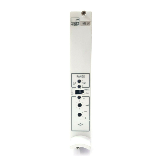
ME 30 Putting into Operation If the factory settings, such as the measuring range or zero balance are re- tained, the operation is limited to setting the zero point and the measuring ranges. 3.1 Select Measuring Range With the factory setting measuring range 1 ( 2mV/V) is always switched on. Measuring range 2 (calibration at 0.2mV/V) can be selected either internally via DIP switch 24/4 or externally by closing a single-pole change-over switch to pin 25c against operating voltage zero (see chapter 4.2). - Page 13 ME 30 ME30 Fig. 3.1: Front view ME30...
-
Page 14: Individual Settings
ME 30 Individual Settings Various ex-works settings on the measuring amplifier card can be altered. Adaptations, which are of no problem, can be carried out by means of the DIP switch on the board or also by externally wired switching elements. If re- quested with the order, they can be carried out by the manufacturer. -
Page 15: External Fine Balancing Of The Mr1
ME 30 = 5V MR1:S26 ; MR2:S27 ex-works sett. Meas. range (mV/V) 0.17 0.24 MR 2 0.2mV/V 0.22 0.32 0.30 0.42 0.39 0.55 0.52 0.73 0.68 0.97 0.90 1.28 1.18 1.69 1.56 2.23 MR 1 2mV/V 2.07 2.94 2.73 3.88 3.61 5.13 o = open, x = closed... -
Page 16: Bridge Fine Balancing
ME 30 4.4 Bridge Fine Balancing a) Coarse Balancing The 16-stage switch S22 is used for the coarse balancing carried out from the front panel; the polarity of the balancing direction can be chosen via switch S23. The overall balancing range is approximatly 2mV/V. -
Page 17: Measuring Frequency Range / Cut-Off Frequency Fco
= 2.5Hz (–3dB) 4.7 Synchronization When operating several ME30 amplifiers (in a common housing), one of them has to be switched as the master the carrier frequency of which supplies the clock pulses, the others are to be switched as slave. Pins 11c of all amplifiers have to be joined for synchronization. -
Page 18: Options
ME 30 Options 5.1 Stabilized Power Supply The module KM001 can be used if the amplifier is connected to a symmetri- cal unregulated supply voltage of 15.6...25.0V. The module supplies the two stabilized supply voltages internally to the amplifier.When installing the mod- ule KM001, attention should be paid to the marking (bridge 3 and bridge 4 on pin 1 and 2). -
Page 19: Current Output Module
SD01 are used conforming to the protection classes (EEx ib IIC) accord- ing to VDE0171, EN 50 014 and EN 50 020 (see data sheet). 5.5 Additional Units The following additional cards are available for the measuring amplifier ME30: – automatic zeroing unit NE02 – peak / last value memory SE03... -
Page 20: General Notes
Certain regulations concerning electrical installation have to be observed in plants with strongly disturbed supply mains systems. The most important points are listed up in the HBM leaflet ”Hints for connection/disturbances”. An extensive summary is given in the installation regulations VDI/VDE 3551. The... -
Page 21: Technical Data
ME 30 Technical Data Type ME30 Carrier frequency 600 0.5% Bridge excitation voltage 2.5 2% 5 0.2% Transducers which can be connected strain gauge transducers (full bridge) 60...4000 110...4000 maximum cable length Number of measuring ranges measuring ranges, adjustable in 12 steps mV/V 0.4...8... - Page 22 ME 30 Technical Data (Continuation) µV/V Noise, referred to input <0.2 (peak-to-peak); typ.0.1 Linearity deviation related to nominal voltage <0.02; typ. 0.01 Temperature influence per 10K in nominal temperature range on measuring sensitivity <0.1; typ. 0.05 on zero point at amplifier output in MR 2mV/V at U =5V (4x350Ω) <4, resp.
-
Page 23: Component Layout
ME 30 Component Layout... -
Page 24: Copy Of Declaration Of Conformity
ME 30 Copy of Declaration of Conformity... - Page 25 ME 30...
- Page 26 ME 30...
- Page 27 ME 30...
- Page 28 Modifications reserved. OTTINGER ALDWIN ESSTECHNIK All details describe our products in HBM Mess- und Systemtechnik GmbH general form only. Postfach 10 01 51, D-64201 Darmstadt They are not to be understood as express Im Tiefen See 45, D-64293 Darmstadt warranty and do not constitute any liability Tel.: +49/ 61 51/ 8 03-0;...
Need help?
Do you have a question about the ME30 and is the answer not in the manual?
Questions and answers