Table of Contents
Advertisement
Advertisement
Table of Contents

Related Manuals for HBM SCOUT55


Summary of Contents for HBM SCOUT55
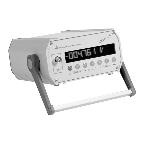
- Page 1 Operating manual Measuring amplifier in desktop housing SCOUT55 A0236-5.9 en...
-
Page 3: Table Of Contents
Scout 55 Contents Page Safety instructions ..........1 Introduction . - Page 4 Scout 55 3.4 Button functions in programming mode ..... . 3.4.1 Changing from “Measuring” mode to “Programming” mode ........3.4.2 Programming .
-
Page 5: Safety Instructions
Scout 55 Safety instructions SCOUT55 can be operated either at 230 VAC or 110 VAC, 48...60 Hz mains voltage. For adapting the device to the mains voltage, please see chapter 2.3.1 in the operating manual. Before connecting the device, make sure that the mains voltage and current... - Page 6 Protect the device from direct sunlight. Ensure sufficient ventilation. General dangers in the case of non-observance of the safety instructions The SCOUT55 complies with the state of the art and is operationally reliable. If the device is used and operated inappropriately by untrained personnel, residual dangers might develop.
- Page 7 Scout 55 In this manual, the following symbols are used to point out residual dangers: DANGER Symbol: Meaning: Maximum danger level Warns of an imminently dangerous situation in which failure to comply with safety requirements will result in death or serious bodily injury. WARNING Symbol: Meaning:...
- Page 8 Reconstruction and modifications HBM’s express consent is required for modifications regarding the SCOUT55’s construction and safety. HBM does not take responsibility for damage resulting from unauthorized modifications. In particular, repair and soldering works on the boards are prohibited. If complete componentry is replaced use original HBM components, only.
- Page 9 You are also authorized to activate, to ground and label circuits and equipment in accordance with safety engineering standards. Maintenance and cleaning SCOUT55 devices are maintenance-free. Please note the following points when cleaning the housing: − Withdraw the mains plug from the socket before carrying out any cleaning.
-
Page 10: Introduction
Scout 55 Introduction 1.1 Scope of supply D Device with mounting frame / carrying handle D 1 male cable connector DB-15P, order no.: 3.3312−0182 D 1 mains cable D 1 male terminal strip connector 3−pin (interface) D 2 male terminal strip connectors 9−pin (control inputs/outputs) D 1 Operating Manual Part1;... -
Page 11: General
Scout 55 1.2 General The SCOUT 55 measuring amplifier is suitable for recording and processing measured values from passive transducers. The essential features: D Transducers that can be connected: S.G. full and half bridges, inductive full and half bridges, piezoresistive and potentiometric transducers, LVDT D 10-digit alphanumeric display D Using the touch-sensitive keypad D 2 peak value stores for maximum and minimum values, as well as... -
Page 12: Connections
Scout 55 Connections Observe the safety instructions before commissioning the device. 2.1 Factory settings Before operating the device, check the parameters set at the factory and note that the elements for selecting the analogue output signal (current/voltage output) and for setting synchronisation, are located on the motherboard. The factory settings are given below: D Mains voltage: 230 V / 50...60 Hz or 115 V / 50..60 Hz, depending on order D Analogue output: output voltage "10 V... -
Page 13: Setting The Analogue Output Signal
Scout 55 2.2.1 Setting the analogue output signal Select the analogue output signal (voltage or current) by replugging jumpers ST11 (see Fig. 2.1). Choose between "20 mA or 4...20 mA in the control dialogue. 2.2.2 Choosing the operating mode for synchronisation To synchronise several devices, set one device as the Master. -
Page 14: Changing The Mains Voltage Selection/Replacing The Fuse
Scout 55 2.3.1 Changing the mains voltage selection/replacing the fuse window 230V cover replace fuse(s) fuse holder 230V 230 V: T63mA L 115 V: T125mA L cover open fuse holder Back of device: choosing mains voltage, replacing fuses Fig. 2.3: The mains voltage currently selected (e.g. -
Page 15: Device Mounting
Scout 55 Replacing the fuses: Switch off the device and take out the mains cable. 1 Lever off the cover and fold it forward 2 Take out the fuse holder 3 Replace the fuses − Fit the fuse holder, paying attention to the correct mains voltage (the chosen value can be seen in the “window”). - Page 16 Scout 55 BU 1 Transducer connection socket S.G. and inductive full bridges S.G. and inductive half bridges piezoresistive transducers Measurement signal (+) Measurement signal (+) Voltage (−) Voltage (−) Measurement signal (−) Voltage (+) Voltage (+) Sensor circuit (+) Sensor circuit (+) Sensor circuit (−) Sensor circuit (−) Cable shielding...
-
Page 17: Analogue Output
Transducer connection in four-wire technique Fig. 2.6: NOTE To connect the transducers, use HBM standard cable. If you use another shielded, low-capacitance measurement cables, connect the shielding of the transducer cable to the connector housing, in accordance with HBM Greenline information (see http://www.hbm.com/Greenline). This guarantees EMC protection. -
Page 18: Control Inputs / Outputs
Scout 55 Á Á Á Á Á Á Á Á Á Á Á Á Á Á Á Á Á Á Á Á Á Á Á Á Á Á Á Function Function Á Á Á Á Á Á Á Á Á Á Á Á Á Á Á... -
Page 19: Synchronisation
Scout 55 SCOUT 55 relay max. 0.5A max. 0.5A 24V* 24V* external supply voltage of the control outputs Output assignments Fig. 2.9: * The control inputs and outputs are available at the terminal strip socket (9−pin) and are potential-separated by optical couplers. The control outputs must be supplied with an external voltage (ground 24 V). -
Page 20: Connecting The Serial Interface
Scout 55 2.8 Connecting the serial interface On the back of the device, there is an RS232 serial interface for connecting a computer or a terminal. When connecting a printer, a simple line printer needing no more than 4 seconds to print a line is sufficient. The printout has 12 columns. - Page 21 Scout 55 NOTE If the error message CALERR. appears here, the following can be the causes: − no six-wire feedback connected − incorrect transducer/sensor connection − no transducer/sensor connected Remedy: Switch off the device. Connect the transducer properly. Switch the device back on.
- Page 22 Scout 55 Piezoresistive transducers: Adaptation: Transducer type: Half bridge Excitation: 2.5 V Input: 400 mV/V Calibration: Unit, nominal value/ decimal point: 30,000 BAR Measuring range: 200 mV/V Potentiometric transducers: Adaptation: Transducer type: Half bridge Excitation: Input: 1000 mV/V Calibration: Unit, nominal value/ decimal point 10,000 mm Measuring range:...
- Page 23 Scout 55 Key to symbols select number Group old setting Parameter new value change value MEAS. MODE press for 2 sec DIALOG LANGUAGE Language ENGLISH DEUTSCH press once ADAPTATION transducer adaptation Continued on next page A0236-5.9 en...
- Page 24 Scout 55 S.G. force Inductive Piezoresistive transducer Potentiometric transducer displacement transducer transducer (= factory settings) TRANSDUCER Transducer type LVDT HALF BRG. HALF BRG. HALF BRG. FULL BRG. Setting the excitation voltage EXCITATION 2.5 VOLT 1.0 VOLT 2.5 VOLT 1.0 VOLT Input signal INPUT 400mV/V...
- Page 25 Scout 55 S.G. force Inductive Piezoresistive Potentiometric transducer displacement transducer transducer transducer (= factory settings) UNIT Measured quantity unit ....NOM. VALUE Nominal value input ....20000 kN 20000 mm 30000 BAR 10000 mm Press four times (skip decimal point, digit step, zero value) dEc.P RANGE...
- Page 26 Scout 55 Switch to measuring mode Press for 2s SAVE The settings are saved in parameter set 1 and the device switches to measuring mode. You can now run an initial function test. NOTE The settings are only power fail safe once they have been saved under one of the parameter sets.
-
Page 27: Control Concept And Functional Overview
Scout 55 3.2 Control concept and functional overview The control concept makes a distinction between two types of button functions: − keys that are operative during measuring mode and − keys effective in programming mode. Measured value display, parameter presentation Button row Measuring mode Change... -
Page 28: Button Functions In Measuring Mode
Scout 55 3.3 Button functions in measuring mode Meaning Change from Measuring mode to Programming mode (and vice versa) by pressing for approx. 2s. Set the limit values LV1...4 (see from Page 41) The additional parameters of the limit switches such as hysteresis, direction etc., are unchanged. - Page 29 Scout 55 MEAS. MODE LV1 LEVEL (LIMITVAL.1) The current limit value is displayed. Fast run Apply input signal Numerical value entry for as limit value limit values (LV1 LEVEL) Keep pressed Save changes power Press for 2 sec, fail safe SAVE is displayed SAVE DONE is displayed LV1 to LV4 are saved power fail safe;...
-
Page 30: Button Functions In Programming Mode
Scout 55 3.4 Button functions in programming mode In this operating mode, you can make all the settings for using the amplifier in your application. The parameters are collected into groups. Meaning of the keys: Change mode (press for 2 sec), select group (e.g. CALIBR.) Parameter selection (e.g. -
Page 31: Programming
Scout 55 3.4.2 Programming Typical programming mode operations Entering a numerical value as Selecting the value/parame- Apply a signal produced by the a parameter (example CAL- ter from a given table (exam- transducer when a defined load- IBR./ ple DIALOG-LANGUAGE) ing occurs RANGE) DIALOG... -
Page 32: Switching From "Programming" Operating Mode To "Measuring" Operating Mode
Scout 55 3.4.3 Switching from “Programming” operating mode to “Measuring” operating mode When the parameters are changed, you will be asked whether the modified parameters are to be saved power fail safe. Press for 2s SAVE saved power fail safe SAVE DONE Saved power fail safe in current parameter set... -
Page 33: Overview Of All Groups And Parameters
3.5 Overview of all groups and parameters Groups DIALOG PARAM. SET ADAPTATION CALIBR. LIMITVAL.1...4 PV STORE IN/OUT ADD. FUNCT. LANGUAGE RECALL TRANSDUCER UNIT ENABLE ENABLE SOURCE UA PASSWORD SAVE ? EXCITATION NOM. VALUE SOURCE PVS1 MODE UA SERIAL No. BUTT. LVS DEC. -
Page 34: Setting All Parameters
3.5.1 Setting all parameters 2sec SCOUT 55 Password 00000 Groups adaptation PARAM. SET +0000 CODE DIALOG PARAM DEUTSCH PARAM Enter password PARASET 1 _ _ _ _ ENGLISH PARASET 2 press twice LANGUAGE FRANCAIS PARASET 3 RECALL ITALIANO PARASET 4 ESPANOL PARASET 5 PARASET 6... - Page 35 SCOUT 55 groups parameter set PV STORE CALIBR. ADAPTATION LIMIT VALUE 1...4 FULL BRG. PARAM HALF BRG. PARAM PARAM LVDT TRANSDUCER UNIT ENABLE 2.5 VOLT EXCITATION 1.0 VOLT GROSS.VALUE SOURCE NOM. VALUE 4 mV/V +010 000 V NET VALUE INPUT PVS1 MAX 40 mV/V PVS2 MIN...
- Page 36 SCOUT 55 Groups LIMITVAL.1...4 ADD. FUNCT. IN/OUT PV STORE PARAM PARAM PARAM GROSS.VALUE NET VALUE 9600 BAUD PVS1 MAX PVS OFF SOURCE UA 4800 BAUD ENABLE PVS2 MIN PVS ON SERIAL NO. 2400 BAUD PVS3 PP 1200 BAUD 600 BAUD BAUDRATE 10 VOLT 300 BAUD...
-
Page 37: Dialogue
Scout 55 3.5.2 Dialogue Select language (LANGUAGE) Factory settings: DEUTSCH You can choose the following languages: German (DEUTSCH), English (ENGLISH), French (FRANCAIS), Italian (ITALIANO), Spanish (ESPANOL) 3.5.3 Load/Save in parameter set (PARAM. SET) The current device amplifier settings can be saved power fail safe in eight parameter sets and later queried. - Page 38 Scout 55 EXCITATION: The excitation voltage for the transducer is selected. Selectable excitation voltages 2.5 V INPUT: Depending on which excitation voltage is chosen, the input range (approximate measuring range) can be selected for the transducer type. Input range UB = 2.5 V UB = 1 V "4 mV/V "10 mV/V...
- Page 39 Scout 55 FILTERS: Different low-pass filters (characteristics and cut-off frequencies) can be selected: Characteristics Bessel (BE) Sampling rate Butterworth (BU) Sampling rate (Hz) (measured (Hz) (measured values values per sec) per sec) 0.05 18.75 1200 37.5 1200 1200 1200 1.25 1200 1200 1200...
-
Page 40: Calibration (Calibr.)
Scout 55 Display Tolerance field (MOTION DIG) units (number of measurements Time within time interval t) Standstill Warning Effect of the motion count Fig. 3.1: 3.5.5 Calibration (CALIBR.) UNIT You can select the following units: Selectable unit ‰ M/SS KPAS HPAS mm/m INLB... -
Page 41: Limit Values 1
Scout 55 DEC. POINT Changes the position of the decimal point. Selectable positions .0000 0.000 00.00 000.0 0000 For above example a: .00 for above example b: .000 STEP You can choose the step or the digit step. Selectable steps 50 100 200 500 1000 ZERO VALUE The maximum zero balance range matches the particular maximum... -
Page 42: Set Peak Value Store (Pv Store)
Scout 55 ENABLE Disable individual limit switches Enable individual limit switches SOURCE Limit value evaluated. GROSS.VALUE Gross NET VALUE PVS1 MAX Store for maximum values PVS2 MIN Store for minimum values Store for peak-to-peak value PVS3 PP SWITCH DIR. Specify the switch direction or the working direction here (see Fig. 3.2). rising HIGHER Switch-on level greater than switch-off level for... - Page 43 Scout 55 Use key to display Max/Min values in measure mode. An additional value is determined arithmetically. PVS3 Store for peak-to-peak value Linking with PVS1 regarding control functions and envelope. Both can be operated as peak value stores or as instantaneous value stores. The choice of operating mode is made with the remotes (see Page 45).
-
Page 44: Inputs And Outputs (In/Out)
Scout 55 You can set the following parameters: ENABLE: You can enable or lock the peak value stores. Enable peak value store PVS ON peak-value memory/buffer/store locked PVS OFF PVS1 INPUT: Choice of input signal for peak value store PVS1. GROSS.VALUE NET VALUE PVS2 INPUT:... - Page 45 Scout 55 MODE UA: Depending on the analogue signal you select, the following options are possible: Display Meaning UA OFF − 0 TO 20mA Output "20 mA 4 TO 20MA Output +4.. 20 mA UA OFF − 10 VOLT Output +/− 10 V NOTE The current output or voltage output selection is made using jumpers on the amplifier motherboard.
- Page 46 Scout 55 Functions Level 0V Level 24V NO FUNCT. no function (factory setting) AUTOCAL Autocalibration ON Autocalibration OFF TARE For the transition 0V − 24 V, the tare value is adopted PVS1 INST Peak value operating mode for Instantaneous value operating mode for PV1 PVS1/HOLD Store contents PV1 and PV3 are...
-
Page 47: Additional Functions (Add. Funct)
In order to provide better support should you experience technical problems, the firmware status is indicated by this parameter. If you have any questions for our service department or HBM branch, giving the existing firmware version will enable us to provide effective support. - Page 48 Scout 55 PRINT MAX: Output the maximum value over the serial interface. OFF/ON PRINT MIN: Output the minimum value over the serial interface. OFF/ON PRINT PP: Output the MIN/MAX value over the serial interface. OFF/ON PRINT LVS: Output limit switch states over serial interface. OFF/ON PRINT OVERL Adjust repetition rate.
-
Page 49: Example
Scout 55 ZERO/TARE: Any change to the tare value or the zero value made by keys (green) or remotes, is automatically stored in the current parameter set. This protection can be switched on or off: SAVE OFF SAVE ON Example The following example uses a measurement task to show you the functionality of the device and the required settings. -
Page 50: Wiring Diagram
Scout 55 Wiring diagram: SCOUT 55 Power supply 0 / 24V Limit3 Emergency shutdown Limit1 press C9B/10kN Logical PVS1 evaluation of limit values 1 and 2 Limit2 START CONTACT 1 / PVS1 INST Serial interface for document printer, host computer, PLC, etc. Timing diagram: Limit3 Limit2... - Page 51 Scout 55 Using the PLC to evaluate the limit value message: Good Reject Limit1 Limit2 Choose the following settings: Limit1 Checks whether the lower force limit has been reached. The input signal is the output of the peak value store (maximum value).
- Page 52 Scout 55 Key to symbols select number Group old setting Parameter new value change value MEAS. MODE press for 2 sec Programming mode Dialogue LANGUAGE ENGLISH DEUTSCH A0236-5.9 en...
- Page 53 Scout 55 Change group press twice ADAPTATION _ _ _ _ Transducer TRANSDUCER 100Hz BE type LVDT Change group press once FULL BRG. Amplifier adjust- CALIBR. ment Setting the EXCITATION Measured excitation UNIT quantity unit voltage 2.5VOLT ..INPUT Input signal Nominal value input dEc.P 400mV/V...
- Page 54 Scout 55 dEc.P RANGE Range Decimal DEC. POINT point input Transducer signal in accordance ..with the desired 00,60000 mV/V display range 0000 Change group Set limit switches LIMITVAL.1 1...4 dEc.P STEP Digit step input Limit switch locked ENABLE 000000 or enabled 000005 ZERO VALUE...
-
Page 55: Scout
Scout 55 SWITCH DIR. Effective direction Remotes logic LOGIC LOWER HIGHER ACTIVE.LOW ACTIVE.HIGH LEVEL dEc.P Limit value 1 Limit switch LV BUTT button function 0100 +003500 N NET VALUE ENABLED Hysteresis dEc.P HYSTERESIS value input Set limit switches 2, 3 and 4 accordingly .. - Page 56 Scout 55 Change group Change group press once Adjusting peak PV STORE value stores IN/OUT I/Os Peak value store ENABLE Signal sources locked or enabled SOURCE UA selectable PVS OFF NET VALUE PVS ON GROSS.VALUE Input signal PVS 1 INPUT choice, store 1 Set output MODE UA...
- Page 57 Scout 55 INPUT SIGN. Input signals ZEROSIGNAL MEAS.SIGNAL Pin assignment of CONTACT 1 remotes 1...6 NO FUNCT. PVS1 INST press for 2 sec Query, whether changes SAVE are to be saved SAVE DONE Save changes press once Measuring mode A0236-5.9 en...
-
Page 58: Error Messages
Scout 55 Error messages Error message Cause Remedy The given value cannot be altered. Example: For unit V and mV/V, the nominal value setting is fixed at 10,000 OVFL B Gross value overflow OVFL N Net value overflow CAL.ERR incorrect transducer/ Connect the transducer properly. -
Page 59: Keyword Index
SCOUT 55 Keyword index adaptation, 37 gross, 28 aditional functions, 47 gross signal, 20 autocalibration, 38 , 46 gross value, 42 baud rate, 47 hysteresis, 41 , 42 BNC−connector (female), 18 inductive displacement transducer, 24 calibration, 40 inductive transducers, 15 control inputs−... - Page 60 SCOUT 55 net, 28 S.G. force transducer, 24 net value, 42 S.G. transducers, 15 serial interface, 20 SET, 28 setting parameters, 34 output logic of the remotes, 42 step, 41 output signal, 44 stop bit, 47 switch direction, 42 synchronisation, 13 , 19 parameter, save, 32 parameter set, 46 load/save, 37...
- Page 64 Hottinger Baldwin Messtechnik GmbH 7-2002.0674 Postfach 10 01 51, D-64201 Darmstadt Im Tiefen See 45, D-64293 Darmstadt Tel.: +49 6151 803-0 Fax: +49 6151 8039100 Email: support@hbm.com Internet: www.hbm.com A0236-5.9 en...
Need help?
Do you have a question about the SCOUT55 and is the answer not in the manual?
Questions and answers