Table of Contents
Advertisement
Advertisement
Table of Contents

Related Manuals for HBM MX840B


Summary of Contents for HBM MX840B
- Page 1 Operating Manual English Quantum...
- Page 2 Tel. +49 6151 803-0 Fax +49 6151 803-9100 info@hbm.com www.hbm.com Mat.: 7-2002.3031 DVS: I3031-14.0 HBM: public 09.2016 E Hottinger Baldwin Messtechnik GmbH. Subject to modifications. All product descriptions are for general information only. They are not to be understood as a guarantee of quality or...
-
Page 3: Table Of Contents
........6.4.5 Backplane with Ethernet connection ......Quantum I3031-14 .0 HBM: public... - Page 4 ......7.2.10 Output measurement signals to CAN bus (MX840B) ... .
- Page 5 8.2.2 MX840B status display ........
- Page 6 ........Quantum I3031-14 .0 HBM: public...
- Page 7 ....12.5 Accessories for MX840B, MX440B ......
-
Page 8: Safety Instructions
In the event of a fault, these precautions establish safe operating conditions. This can be done, for example, by mechanical interlocking, error signaling, limit value switches, etc. Quantum I3031-14 .0 HBM: public... - Page 9 After making settings and carrying out activities that are password-protected, you must make sure that any controls that may be connected remain in safe condition until the switching performance of the module has been tested. Quantum I3031-14 .0 HBM: public...
- Page 10 S When cleaning, ensure that no liquid gets into the module or connections. Outputs Particular attention must be paid to safety when using the digital, analog or CAN bus outputs of a module. Ensure Quantum I3031-14 .0 HBM: public...
- Page 11 Averting the danger S Warning sign: draws attention to the danger S Signal word: indicates the severity of the danger (see table below) S Type of danger: identifies the type or source of the danger Quantum I3031-14 .0 HBM: public...
- Page 12 The supply connection, as well as the signal and sensor leads, must be installed in such a way that electromagnetic interference does not adversely affect device functionality (HBM recommendation: "Greenline shielding design", downloadable from the Internet at http://www.hbm.com/Greenline). Automation equipment and devices must be covered over in such a way that adequate protection or locking against unintentional actuation is provided (e.g.
- Page 13 Qualified persons means persons entrusted with the installation, fitting, commissioning and operation of the product who possess the appropriate qualifications for their function. This module is only to be installed and Quantum I3031-14 .0 HBM: public...
- Page 14 It is also essential to comply with the legal and safety requirements for the application concerned during use. The same applies to the use of accessories. Quantum I3031-14 .0 HBM: public...
-
Page 15: Electro Magnetic Conformity
When used in residential or commercial environments, additional ar rangements may be required to limit electro-magnetic emissions. An example is voltage supply of the modules by battery. In this case please wrap the power supply cable Quantum I3031-14 .0 HBM: public... - Page 16 (KAB271-3) around the inductive coil included in the package four times. ODU plug When the NTX001 power supply from HBM is used, the system complies with Emissions: Class B without the necessity to carry out the meaasure described above. Quantum...
-
Page 17: Markings Used
Bold text in italics indicates inputs and input fields in the user interfaces. Emphasis Italics are used to emphasize and highlight text and See … identify references to sections, diagrams, or external documents and files. Quantum I3031-14 .0 HBM: public... -
Page 18: Symbols On The Device
CE marking enables the manufacturer to guarantee that the product complies with the requirements of the relevant EC directives (the Declaration of Conformity can be found on the HBM website (www.hbm.com) under HBMdoc). Statutory waste disposal mark In accordance with national and local environmental... -
Page 19: Introduction
These documents can be found S on the QuantumX system CD supplied with the device EtherCAT® is a registered brand and patented technology, licensed by Beckhoff Automation GmbH, Germany Quantum I3031-14 .0 HBM: public... -
Page 20: The Quantumx Family
The module has 8 universal inputs and supports more than 15 transducer technologies. S MX440B Universal amplifier Like the MX840B, but with 4 inputs (connections 5-8 of MX840B, without CAN). S MX410B Highly dynamic universal amplifier The module has 4 universal inputs and supports com... - Page 21 25 ppm. S MX460B Digital module (counter, frequency, timer) The module has 4 individually configurable inputs for connecting HBM torque measurement shafts (T12, T40, T10), rotational speed sensors, crankshaft sen sors with gap (TDC sensor), pulse width modulated...
- Page 22 The module has 8 scalable voltage outputs and 32 configurable digital inputs/outputs. Signals can also be calculated in real time. All modules have the following in common: S Supply voltage range 10 … 30 V DC (nominal rated voltage 24 V DC) Quantum I3031-14 .0 HBM: public...
- Page 23 S Configurable digital filter (Bessel, Butterworth) S configurable scaling Sensors assigned using the sensor database can be cal ibrated via the channel and written back into the sensor database. TEDS = Transducer Electronic Data Sheet Quantum I3031-14 .0 HBM: public...
-
Page 24: Module Overview/Transducer Technologies
Introduction Module overview/transducer technologies Quantum I3031-14 .0 HBM: public... -
Page 25: Digitalization And Signal Path
Digitalization and signal path Data rate QuantumX measurement modules with the suffix B, like the MX840B, for instance, have decimal data rates such as 600, 1200, ..19,200 S/sec available, in addition to classic data rates such as 500, 1000, ..100,000 S/sec. -
Page 26: Synchronization
Synchronization methods: Synchronisation via Ethernet IEEE1588:2008 (PTPv2) When modules, for example, MX840B are set to this syn chronization mode and z.B. untereinander mit einem PTP-fähigen Switch connected using a switch with PTP... - Page 27 PTPv2, and included in the synchronization (auto matic clock distribution). The converted modules must be restarted. The system as a whole therefore supports the classic HBM sample rates only. Converted modules need to be restarted. After restart, check the system LEDs at the module front green means synchronous.
- Page 28 Synchronization via an NTP server Each QuantumX module can synchronize its internal clock with an NTP server. The NTP time is distributed to the other modules via IEEE1394b FireWire. Quantum I3031-14 .0 HBM: public...
- Page 29 NTP master is being used. Modules located close together should be synchronized via IEEE1394b FireWire. If the synchronization source for a module is changed to NTP, the system must be restarted once. The HBM cat man®EASY software includes an NTP software pack age. Parameter: S IP address of the NTP server S Threshold in s below which the time deviation to...
- Page 30 (with recom mended PTPv2 switches up to 100 ns) Synchroniza Immediate Up to 20 s Up to 30 min Immediate Immediate tion settling (on initial during first time startup) start, up to 2 min during restart Quantum I3031-14 .0 HBM: public...
- Page 31 EtherCAT® IRIG-B FireWire (PTPv2) (NTP) Synchroniza Auto Auto oder External Syn External External tion 1 QuantumX Grandmas cMaster , SyncMaster IRIG-B master module ter‐ e.g. PC master Clock Voltage sup < 1.5 A, looped through Quantum I3031-14 .0 HBM: public...
- Page 32 (IEEE1394b FireWire to the modules) Auto Auto Auto Time base: NTP server Ethernet Synchronizing via Ethernet / NTP (without IEEE1394b FireWire) Time base: NTP server Ethernet switch CX27 or the module with the highest serial number Quantum I3031-14 .0 HBM: public...
- Page 33 No automatic runtime correction is carried out. The filter runtimes are shown in the data sheet. After booting and successful synchronization, the system LED is lit green. If synchronization is disturbed, or not yet estab lished, the system LED is lit orange. Quantum I3031-14 .0 HBM: public...
- Page 34 There are several synchronization methods to choose from (also see Fig. 4.1 page 33): S Synchronization via IEEE1394b FireWire S Synchronization via EtherCAT® (CX27) S Synchronization via NTP (Network Time Protocol) with IEEE1394b FireWire S Synchronization via NTP without IEEE1394b FireWire Quantum I3031-14 .0 HBM: public...
-
Page 35: Software
4 up to 20,000 channels - Drivers for LabVIEW, Visual Studio .NET, CANape, DIAdem, etc. - Windows device driver for IEEE1394b FireWire MX Assistant The HBM "QuantumX Assistant" software offers the fol lowing functions: System: S Create overview (modules, host PC) Modules:... - Page 36 PID con troller S Map signals to CAN messages (data types) and gene rate CANdb (*.dbc) Sensor database S Write sensor data sheets to TEDS S Add user-defined sensor data sheets, import CANdb (*.dbc) Quantum I3031-14 .0 HBM: public...
-
Page 37: Catman®Ap
Software catman®AP The HBM "catman®AP" software is optimally suited for the following tasks: S Setting the communication and measurement chan nels (integrated TEDS editor and extendable sensor database) S Configuration of measurement or test tasks (chan nels, sampling rates, triggers, comments, interactions) -
Page 38: Labview® Driver / Library
LabVIEW is a graphical programming system from Na “ tional Instruments. The acronym stands for Laboratory ” Virtual Instrumentation Engineering Workbench The main application areas for LabVIEW are in measure ment, control and automation technology. Quantum I3031-14 .0 HBM: public... -
Page 39: Other Drivers
The HBM LabVIEW driver is based on the HBM com mon.NET API. The installation includes some examples and extensive help. -
Page 40: Firmware Update Via Ethernet
S If you want to expand your system with new modules You can also determine the firmware status of your mod ules using the QuantumX Assistant: S Rightclick on the computer in the device overview *> Details *> System overview Quantum I3031-14 .0 HBM: public... -
Page 41: Mechanical
Protection against contact with No water protection fingers, protection against for eign substances with >12 Both housing types can be connected together with the aid of two lateral housing clips (1-CASECLIP, not in Quantum I3031-14 .0 HBM: public... -
Page 42: Mounting Case Clips On Modules
Case protection MX840 housing Cover Fig. 6.1 Amplifier MX840 with case protection The mounting of the housing clips shown in the following pictures must be implemented on both sides of the hous ing. Quantum I3031-14 .0 HBM: public... - Page 43 Mechanical 2.5 a.f. Fig. 6.2 Removing the case protection Cover Fig. 6.3 Removing the cover Quantum I3031-14 .0 HBM: public...
- Page 44 Mechanical Case clip 2.5 a.f. Fig. 6.4 Mounting the case clip CASECLIP 2.5 a.f. Fig. 6.5 Mounting the case protection CASEPROT Quantum I3031-14 .0 HBM: public...
-
Page 45: Connecting Housings
Mechanical Connecting housings The following pictures show the connection of two hous ings. Press Fig. 6.6 Unclip the case clip CASECLIP Lever Catch Fig. 6.7 Unclip the lever and catch Quantum I3031-14 .0 HBM: public... - Page 46 Mechanical Fig. 6.8 Close the lever Fig. 6.9 Connected housings Quantum I3031-14 .0 HBM: public...
-
Page 47: Mounting The Housing With Casefit
(RACK) allows up to 9 modules to be connected with hardly any wiring. The backplane also has two additional FireWire inter faces for integrating distributed modules or for direct con nection to a PC or data recorder. The IEEE1394b FireWire interfaces are actively interconnected. Quantum I3031-14 .0 HBM: public... - Page 48 The BPX002 backplane for rack mounting in a 19” enclosure. The BPX002 backplane is an extension of the BPX001. Slot 9 Slot 1 Fig. 6.11 Example of QuantumX backplane fitting Quantum I3031-14 .0 HBM: public...
-
Page 49: Connection
VG strip Module connection IEEE1394b FireWire X1 / X2 (PC, external modules) Fuses with control LEDs 4 x 4 A/T Supply voltage 18 V ... 30 V DC 5 A max. Grounding Fig. 6.12 BPX001 connections Quantum I3031-14 .0 HBM: public... -
Page 50: Backplane Bpx001
( 6.5 mm). We recommend using the outer 4 drill holes for wall mounting. Notice Only use countersunk screws for fastening. Otherwise the modules cannot be mounted correctly. 56.75 140.75 229.75 318.75 407.75 Fig. 6.13 BPX001 drilling pattern and dimensions Quantum I3031-14 .0 HBM: public... - Page 51 (vertical air flow) or cooling must be provided (the maximum total output on a backplane is approx. 150 watts) S The ventilation slots of the modules must not be covered (by cable ducts, etc.) Quantum I3031-14 .0 HBM: public...
-
Page 52: Backplane Bpx002
Mechanical 6.4.3 Backplane BPX002 214.5 482.6 448.5 Fig. 6.14 Rackmontage BPX002 6.4.4 Mounting the modules Tools We recommend a T-handle Allen wrench 4x150 (4 mm across flats, length 150 mm). Quantum I3031-14 .0 HBM: public... - Page 53 (the screws are secured against falling out!). 3. Position the module vertically on the backplane and push it in carefully on the lower guide rail back up to the stop. Quantum I3031-14 .0 HBM: public...
- Page 54 Mechanical Upper screwed clamping gland 4,0 a.f. Opening for con nection to Ethernet Guide rails Lower screwed clamping gland Fig. 6.16 Mounting the module Fig. 6.17 Centering above the connection plug Quantum I3031-14 .0 HBM: public...
- Page 55 Mechanical 4. Tighten the lower then the upper screwed clamping gland. Fig. 6.18 Tightening the screwed clamping glands, sequence Quantum I3031-14 .0 HBM: public...
-
Page 56: Backplane With Ethernet Connection
The individual modules can also be connected directly via Ethernet on the back, with maximum sampling rate. In this case, no gateway is required. BPX001 + CX27 Fig. 6.19 Connecting a backplane via Ethernet Quantum I3031-14 .0 HBM: public... -
Page 57: Backplane With Ieee1394B Firewire Connection
FireWire directly to a PC or data recorder. The second IEEE1394b FireWire socket on the back plane can be used to integrate distributed modules into the system. FireWire KAB293-5 BPX001 Fig. 6.20 Connecting a backplane via IEEE1394b FireWire Quantum I3031-14 .0 HBM: public... -
Page 58: System Layout With Several Backplanes
System layout with several backplanes Multiple BPX backplanes can be synchronized via CX27 gateway modules. Connection of CX27 to CX27 via KAB2722 or 5, via front IEEE1394b FireWire connec tion. Fig. 6.21 Synchronizing multiple backplanes Quantum I3031-14 .0 HBM: public... -
Page 59: Connecting Individual Quantumx Modules
We recommend installing an uninterruptible power supply (UPS) in vehicles with battery operation between battery and module to compensate for voltage drops during start procedures. Module Typical power consumption, including transducer excitation (watts) MX840B MX440B MX410B MX430B MX238B MX460B Quantum I3031-14 .0 HBM: public... - Page 60 The maximum permissible current on the IEEE1394b FireWire connection cable is 1.5 A. If the chain is longer, repeating the supply connection is mandatory. If several amplifiers are operated non-synchronously (see Fig. 7.3), they must be supplied separately. Quantum I3031-14 .0 HBM: public...
- Page 61 Connecting individual QuantumX modules NTX001 X104 1-Kab271-3 X101/X102 1-KAB272 FireWire Fig. 7.1 Connecting socket for supply voltage Quantum I3031-14 .0 HBM: public...
-
Page 62: Connection To Host Pc Or Data Recorder
X100 Fig. 7.2 Single Ethernet connection Notice You must use an Ethernet crossover cable with older computers. Newer PCs/laptops have Ethernet interfaces with autocrossing function. You can also use Ethernet patch cables for this purpose. Quantum I3031-14 .0 HBM: public... -
Page 63: Multiple Ethernet Connection With Ptp Synchronization
Modules can be connected to the PC via Ethernet PTPv2‐compliant switches. We recommend patch cables. Here are some examples: - EX23-R from HBM - Scalance XR324-12M from Siemens - RSP20 or MACH1000 from Hirschmann - Ha-VIS FTS 3100-PTP from Harting... -
Page 64: Multiple Ethernet Connection And Firewire Synchronization
Example of multiple connection via Ethernet with synchronization The supply voltage for the modules is looped through FireWire in the configuration shown above (max. 1.5 A through FireWire; for power consumption of the modules, see Chapter 7). Quantum I3031-14 .0 HBM: public... -
Page 65: Connecting One Or More Quantumx Modules To The Pc
S FireWire adapter addressing (e.g. expressCard/34 or PCIexpress) at the PC or data logger end uses a pre viously installed Windows device driver from HBM, and cannot be modified. The modules are automatic ally addressed (plugandplay and USB), and are available immediately. - Page 66 S An activated WiFi connection on your PC: Switch off this connection, if necessary, and restart the network search. S The relevant scan ports not being enabled in the fire wall settings of your PC. Quantum I3031-14 .0 HBM: public...
- Page 67 DHCP as well. S Manual configuration: Deactivate DHCP and enter the same subnet mask address as used with your PC. Change the IP address of your module so that it permits communication (see example below) Quantum I3031-14 .0 HBM: public...
- Page 68 255.255.248.0 Module after 172.21.108.1 255.255.248.0 The first three digit groups of the PC and module IP addresses should be the same. The subnet mask address digit groups must be identical in the module and PC! Quantum I3031-14 .0 HBM: public...
- Page 69 Connecting individual QuantumX modules Automatic configuration Module settings PC settings 172.21.108.1 Module settings 255.255.248.0 Manual configuration PC settings Fig. 7.5 Example of settings for a direct connection Quantum I3031-14 .0 HBM: public...
- Page 70 S Mark your LAN connection with a right-click and select “ ” Properties in the context menu. “ ” “ S Select the General tab and under This connection ” uses the following items mark Internet (TCP/IP). “ ” Click on the Properties button. Quantum I3031-14 .0 HBM: public...
- Page 71 ” address Subnet mask lines. Example: – Setting the IP address manually PC side Settings IP address Subnet mask Module before 169.1.1.22 255.255.255.0 PC / notebook before 172.21.108.51 255.255.248.0 PC / notebook after 169.1.1.1 255.255.255.0 Quantum I3031-14 .0 HBM: public...
- Page 72 ” S Activate the DHCP checkbox and click on . The following confirmation window then appears: “ ” S Confirm the settings with the button. The module will then be restarted with the current settings. Quantum I3031-14 .0 HBM: public...
-
Page 73: Firmware Update Via Ethernet
Firmware update via Ethernet We recommend that the firmware and software used to operate QuantumX are always kept up to date. S Download the latest firmware from the HBM website. ® If you do not work with catman , please download the QuantumX software package from the HBM website. -
Page 74: Connection Via Firewire (Ieee 1394B)
General information S Baud rate of 400 MBaud (approx. 50 MByte/s) S Asynchronous (all nodes) or isochronous (in real time) data transmission S Data synchronization S Supply voltage via FireWire connection cable (max. 1.5 A) Quantum I3031-14 .0 HBM: public... -
Page 75: Setting Up Firewire 1394B On The Pc
Setting up FireWire 1394b on the PC S Integrate the FireWire PC adapter into your computer. S Start the Wizard provided by HBM to install the PCFireWire driver. The Wizard is part of the Quan tumX system software package or catman. - Page 76 S The modules have not been properly registered. Click on the FireWire driver in the systray, check the driver after the modules and reinstall it if necessary (hbm1394.sys). S Check all connections between modules. Quantum I3031-14 .0 HBM: public...
-
Page 77: Multiple Firewire Connection
Example of multiple connection via FireWire with synchronization Data is transferred, modules are synchronized in timing and voltage is supplied via the FireWire connections. You can connect a maximum of 12 modules in series with each other. Quantum I3031-14 .0 HBM: public... -
Page 78: Layout With Data Recorder Cx22B‐W
Make certain that at least 10 V is still applied to the last module. 7.2.9 Layout with data recorder CX22B‐W 10 V ... 30 V DC (NTX001, etc.) Connection via Ethernet cable or wireless (WLAN) CX22B-W FireWire connection Fig. 7.8 Layout with CX22‐W Quantum I3031-14 .0 HBM: public... -
Page 79: Output Measurement Signals To Can Bus (Mx840B)
Connecting individual QuantumX modules 7.2.10 Output measurement signals to CAN bus (MX840B) The MX840B amplifier allows channels 28 to output to the CANbus (channel 1). This mode is configured entirely in the MX Assistant. Fig. 7.9 Output to CAN bus (MX840A, connection 1) 7.2.11 Output measurement signals to CAN bus... -
Page 80: Output Of Signals With Standardized Voltage In Real Time (Mx878B Or Mx879B)
These modules also allow onboard different input chan nel calculations, such as matrix calculation for compens ation of parasitic effects in multicomponent transducers, ADDMUL, PID controls or limit value switches. ® This mode is configured using the catman or MX As Quantum I3031-14 .0 HBM: public... - Page 81 Each source in a QuantumX system is distributed into two signals, to which different data rate and filtering para meters can be assigned. For example, the first signal of an input channel with a high data rate, e.g. acceleration sensor with 100 kS/sec Quantum I3031-14 .0 HBM: public...
-
Page 82: Quantumx In The Firewire Group
7.2.14 QuantumX in the FireWire group The number of modules connected in series (daisy chain) is limited to 12. If you want to connect more modules (maximum 24), you must use hubs. Hubs are devices Quantum I3031-14 .0 HBM: public... - Page 83 Total number of modules: 15 Total number of hops: 12 QuantumX module Data sink Longest chain to data sink (max. 12) P3 = Port 3 Fig. 7.13 Example of a star topology with two chains and one Quantum I3031-14 .0 HBM: public...
- Page 84 Connection to Port 1 and/or 2 - Port 4: 2 hops Fig. 7.14 Connection situation on the AVT 1394b hub Notice Always connect the chain with the most modules to Port 3 or Port 4. Quantum I3031-14 .0 HBM: public...
-
Page 85: Optical Firewire Connection
1 hop Max. 300 m Opto- Opto- Displayed: Total number of modules: 11 Total number of hops: 8 QuantumX module Longest chain to data sink Fig. 7.15 Example of the use of optohubs Quantum I3031-14 .0 HBM: public... - Page 86 Connecting individual QuantumX modules 10 V ... 30 V DC Fiber optical cable Max. length 300 m Optohub Optohub Fig. 7.16 FireWire 1394b optohubs and fiber optical cable from HBM partner Allied Vision Technologies Quantum I3031-14 .0 HBM: public...
-
Page 87: Modules And Transducers
(EMI) and the permissible electromag netic interference emissions (EME), has become increas ingly important over the years. The HBM Greenline shielding design The measuring chain is completely enclosed by a Faraday cage by appropriate routing of the cable shield. - Page 88 EMC-proof shield. Shield junc tions must represent a full contact, closed and low-im pedance connection. This is the case for original HBM plug connections. Ground connection and grounding...
-
Page 89: Active Transducer Connection
(or shielding) are designed to be physically separ ate in the HBM devices. The grounded supply connector or a separate ground potential lead should serve as the ground connection, as is the case for potential compens... - Page 90 Adjustable via software Hsg. = Housing CAUTION Check the correct voltage setting when connecting a sensor. Too high a voltage can destroy the sensor. The sensor supply is switched off in condition at the time of delivery. Quantum I3031-14 .0 HBM: public...
-
Page 91: Teds
S the unit of the electrical output signal (mV/V for bridge transducers, for example) S the linear characteristics as the relation between the measured quantity and the electrical signal Quantum I3031-14 .0 HBM: public... - Page 92 S Amplifiers with direct connection of IEPE transducers support TEDS Version 1.0. S A special TEDS module is integrated in some HBM transducers. It can transmit TEDS data via the feed back line of a sensor (patented "zero‐wire circuit").
- Page 93 It starts automatic read ing of the TEDS. ® HBM recommends the TEDSmodule (1Wire EEP ROM) DS24B33 from Dallas Maxim. HBM offers a pack age with 10 TEDS: order no. :1-TEDS-PAK Quantum I3031-14 .0 HBM: public...
-
Page 94: Background Calibration / Autoadjustment
Background calibration briefly interrupts measurement and - in place of the measured values from the trans ducer - sends signals from an internal calibration source to the AD converter (zero and reference signal). Quantum I3031-14 .0 HBM: public... - Page 95 Modules and transducers Background calibration is available for the following amplifiers: MX840B, MX440B, MX1615B, MX430B and MX238B. These amplifiers have a second measurement circuit in the full/half bridge measurement mode, which measures in parallel to the input circuit and implements a calibration cycle in a 30 second rhythm.
-
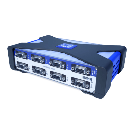
Page 96: Mx840/A/B Universal Amplifier
- Ethernet‐based synchronization via IEEE1588:2008 (PTPv2) - 40 kS/s sample rate per channel, 7.2 kHz band width The MX840B universal amplifier provides 8 channels. Every channel supports over 15 different transducer technologies. The pin assignment of the 15pin DSUB15HD connector with the respective transducer technology or function is identical for all amplifiers using DSUB15HD. - Page 97 Modules and transducers MX840B connectable transducers Transducer type Connection sockets See page SG full bridge 1 ... 8 SG quarter bridge via external ad 1 ... 8 apter Inductive full bridge 1 ... 8 Inductive half bridge 1 ... 8 LVDT 1 ...
-
Page 98: Mx840B Pin Assignment
1 ... 8 PT1000 Thermocouple 1 ... 8 Incremental encoder 5 ... 8 from 161 SSI protocol 5 ... 8 Torque/speed (HBM torque trans 5 ... 8 162, 170 ducer) Frequency measurement, pulse 5 ... 8 from 161 counting CAN bus 8.2.1... - Page 99 (+) signal differential, SSI data (+) Active sensor supply 5 ... 24 V (0 V) Active sensor supply 5 ... 24 V (+) Current input "30 mA (+) Voltage input 10 V (+), 60 V (+) Digital output Quantum I3031-14 .0 HBM: public...
-
Page 100: Mx840B Status Display
Modules and transducers 8.2.2 MX840B status display The front panel of the universal amplifier has a system LED and 8 connection LEDs. The system LED indicates the status of the device, the connection LEDs the states of the individual connections. -
Page 101: Mx440B Universal Amplifier
15-pin D-SUB-15HD device connectors. All measuring channels are electrically isolated from one another and from the power supply. Connectable transducer types and the status display are identical with the universal amplifier MX840A (without CAN) (see page 100). Quantum I3031-14 .0 HBM: public... - Page 102 Flashing orange (5 s), then Manual configuration ongoing (ignore TEDS) green No sensor connected Channel error (incorrectly parameterized, connection error, invalid TEDS data) General rule: Brief flashing TEDS identified (green: is used, orange: is not used). Quantum I3031-14 .0 HBM: public...
-
Page 103: Mx410B Highly Dynamic Universal Amplifier
1 ... 4 SG half bridge 1 ... 4 SG quarter bridge via adapter 1 ... 4 Inductive full bridge 1 ... 4 Inductive half bridge 1 ... 4 Electrical voltage 1 ... 4 150, 151 Quantum I3031-14 .0 HBM: public... -
Page 104: Mx410B Pin Assignment
Pin 4 and Pin 9 in the connector plug must be bridged! If this bridge is missing, no measurement values will be recorded at the connec tion! Bridge Fig. 8.5 Pin arrangement of connector plug, view from the solder side Quantum I3031-14 .0 HBM: public... - Page 105 Voltage input 10 V, IEPE (+) Digital output, for external charge amplifier, etc., 5 V/max. 10 mA The analog output can be tapped via BNC. For configura tion instructions see section 10 "Functions and outputs". Quantum I3031-14 .0 HBM: public...
-
Page 106: Mx410B Status Display
Firmware download active (system is not ready) orange Orange Connection newly assigned, transducer identification running (calibration) Green Error-free operation Flashing green (5s), TEDS data being read in then green Flashing orange (5 s), Manual configuration ongoing (ignore TEDS) then green Quantum I3031-14 .0 HBM: public... - Page 107 MX430B. The transducers are connected via 15-pin D-SUB-15HD device connectors. All measuring channels are electrically isolated from one another and from the power supply. MX430B connectable transducers Transducer type Connection sockets See page SG full bridge 1 ... 4 Quantum I3031-14 .0 HBM: public...
-
Page 108: Mx430B Pin Assignment
Bridge excitation voltage (+) Always connect with Pin 9! (Plug-in detection) Measurement signal (+) TEDS (-) Sense lead (-) Sense lead (+) Signal ground Measurement signal (-) Active sensor supply 5 ... 24 V , (-) Quantum I3031-14 .0 HBM: public... -
Page 109: Mx430B Status Display
System is not ready, boot procedure running Flashing orange Download active, system is not ready Error Connection LEDs All LEDs are orange Boot procedure running (system is not ready) All LEDs are flashing Firmware download active (system is not ready) orange Quantum I3031-14 .0 HBM: public... - Page 110 You can connect up to four transducers to the universal amplifier MX238B. The transducers are connected via 15-pin D-SUB-15HD device connectors. All measuring channels are electrically isolated from one another and from the power supply. Quantum I3031-14 .0 HBM: public...
-
Page 111: Mx238B Pin Assignment
Bridge Fig. 8.9 Pin arrangement of connector plug, view from the solder side Connector TEDS (+) Bridge excitation voltage (-) Bridge excitation voltage (+) Always connect with Pin 9! (Plug-in detection) Measurement signal (+) Quantum I3031-14 .0 HBM: public... -
Page 112: Mx238B Status Display
Active sensor supply 5 ... 24 V (+) Free Free Digital output 8.6.2 MX238B status display System LED Connection LED Fig. 8.10 MX238B front view System LED Green Error-free operation Orange System is not ready, boot procedure running Quantum I3031-14 .0 HBM: public... -
Page 113: Mx460B Frequency Amplifier
General rule: Brief flashing TEDS identified (green: is used, orange: is not used). MX460B frequency amplifier You can connect up to four transducers to the frequency measuring amplifier MX460B. The transducers are con nected via 15-pin D-SUB-15HD device connectors. All Quantum I3031-14 .0 HBM: public... -
Page 114: Mx460B Pin Assignment
So that insertion or removal of a transducer connection can be unmistakably identified, Pin 4 and Pin 9 in the connector plug must be bridged! If this bridge is missing, no measurement values will be recorded at the connec tion! Quantum I3031-14 .0 HBM: public... - Page 115 Active sensor supply 5 ... 24 V (-) Active sensor supply 5 ... 24 V (+) Not in use AC+ (for passive inductive transducers) Digital output, for example to activate a calibration signal for T10F(S) and T40, 5 V/max. 10 mA Quantum I3031-14 .0 HBM: public...
-
Page 116: Mx460B Status Display
Error-free operation Flashing green (5s), then TEDS data being read in green Flashing orange (5 s), then Manual configuration ongoing (ignore TEDS) green No sensor connected Channel error (incorrectly parameterized, connection error, invalid TEDS data) Quantum I3031-14 .0 HBM: public... -
Page 117: Mx1609Kb And Mx1609Tb Thermocouple Amplifier
Up to 16 type T thermocouples (Cu-CuNi) can be con nected to the module MX1609T/TB for measuring tem peratures. Connectable to MX1609 transducers Transducer type Connection sockets See page Thermocouple type K, type T 1 ... 16 Quantum I3031-14 .0 HBM: public... - Page 118 Thermocouple Type Thermocouple material 1 (+) Thermocouple material 2 (–) Nickel-chrome (color code green) Nickel-aluminum (color code white) Copper (color code brown) Copper-nickel (color code white) Connection of the thermocouple plug in the miniature design. Quantum I3031-14 .0 HBM: public...
-
Page 119: Thermocouple With Teds Functionality (Rfid)
C or K). Data is entered with the quired physical unit ( TEDS Editor provided by HBM. It is then written to the RFID chip via a corresponding RFID transponder in the amplifier. - Page 120 S Maximum distance chip to housing: 1 mm S For self-assembly: Check position of chip on plug Thermocouple plug with integrated RFID chip from RFID chip The chip for measuring point identification is already in tegrated in the HBM THERMO-MINI. Quantum I3031-14 .0 HBM: public...
-
Page 121: Mx1609 Status Display
Connection newly assigned, transducer identification run ning (calibration) Green Error-free operation ("Ignore TEDS" or "if available" set, channel is manually configured) Flashing green (5s), then Error-free operation ("Use TEDS" or "if available" set green and TEDS data valid) Quantum I3031-14 .0 HBM: public... -
Page 122: Mx471B Can Module
(e.g. rotational speed or engine temperature). The identifier also signifies the priority of the message. Message = identifier + signal + additional information Device connected to the bus = node Quantum I3031-14 .0 HBM: public... - Page 123 For decoding signals at a rate greater than 2000/s, please set up signal inputs 1 to 8 on the MX471. The sig nal buffers of these signal inputs have been expanded accordingly. Quantum I3031-14 .0 HBM: public...
-
Page 124: Mx471B Pin Assignment
Modules and transducers 8.9.2 MX471B pin assignment Fig. 8.14 Pin arrangement of connector plug, view from the solder side Connector No function CAN Low No function CAN Shield CAN High No function No function Quantum I3031-14 .0 HBM: public... -
Page 125: Leds Status Display
Bus is error-free and no activity on CAN Yellow flickering Intermittent bus errors (warning) and activity on CAN Constant yellow Intermittent bus errors (warning) and no activity on CAN Red on Bus error, CAN interface in "Bus-OFF" status Quantum I3031-14 .0 HBM: public... -
Page 126: Receiving Can Messages
Editors for this purpose are provided by different companies. Received CAN messages are instantly "time-stamped" in measurement mode. This enables directly acquired measured quantities and CAN messages to be acquired and analyzed in parallel and synchronously in the entire system. Quantum I3031-14 .0 HBM: public... -
Page 127: Mx1601B Amplifier
1952089)). All measuring channels are electrically isolated from one another and from the power supply. When using the ad justable transducer excitation, electrical isolation from the supply voltage of the amplifier is not required. Quantum I3031-14 .0 HBM: public... -
Page 128: Mx1601B Pin Assignment
So that insertion or removal of a transducer connection can be unmistakably identified, Pin 2 and Pin 5 in the connector plug must be bridged! If this bridge is missing, no measurement values will be recorded at the connec tion! Quantum I3031-14 .0 HBM: public... - Page 129 Voltage output 10 V (+), 100 mV (+), IEPE (+) Signal ground, TEDS (-) Current input 20 mA (+) TEDS (+) Always connect with Pin 2! (Plug-in detection) Active sensor supply (+) Active sensor supply (-) Housing (shield connection) Quantum I3031-14 .0 HBM: public...
-
Page 130: Mx1601B Status Display
The front panel of the universal amplifier has a system LED and 16 connection LEDs. The system LED indicates the status of the device, the connection LEDs the states of the individual connections. Connection LED System Connection LED Fig. 8.17 MX1601B front view Quantum I3031-14 .0 HBM: public... - Page 131 Amplifier overload, no sensor connected Channel error (incorrectly parameterized, connection error, invalid TEDS data) Flashing red Sensor supply overload General rule: Brief flashing TEDS identified (green: is used, orange: is not used). Quantum I3031-14 .0 HBM: public...
-
Page 132: Mx1615B Amplifier
When TEDS or T−ID is used, the measurement channel is automatically parameterized after connection. Extended functionality for MX1615B : S Potentiometer When TEDS or TID is used, the measurement channel is automatically parameterized after connection. Quantum I3031-14 .0 HBM: public... - Page 133 Potentiometer (only MX1615B) 1 ... 16 The transducers are connected via 8-pin plug terminal connectors (Phoenix Contact FMC 1.5/8-ST-3.5-RFBKBD1-8Q). The measurement channels are only electrically isolated from the power supply of the MX1615, not from each other. Quantum I3031-14 .0 HBM: public...
-
Page 134: Mx1615B Pin Assignment
This is automatically so for all bridge transducers. The bridge only needs to be completed for voltage measurements. If this bridge is missing, no measurement values will be recorded at the connection! Quantum I3031-14 .0 HBM: public... - Page 135 Sense lead (-) Measurement signal (+), voltage input 10 V / 30 V (+) Measurement signal (-), voltage input 0 V / 10 V (-), bridge excitation voltage (+) for quarter bridges Housing (shield connection) Quantum I3031-14 .0 HBM: public...
-
Page 136: Mx1615B Status Display
Connection LEDs All LEDs are orange Boot procedure running (system is not ready) All LEDs are flashing orange Firmware download active (system is not ready) Orange Connection newly assigned, transducer identification running (calibration) Green Error-free operation Quantum I3031-14 .0 HBM: public... - Page 137 Manual configuration ongoing (ignore TEDS) green Amplifier overload, no sensor connected Channel error (incorrectly parameterized, connection error, invalid TEDS data) Flashing red Sensor supply overload General rule: Brief flashing TEDS identified (green: is used, orange: is not used). Quantum I3031-14 .0 HBM: public...
-
Page 138: Transducer Connection
Transducer connection Transducer connection Full bridge, SG Supported by the following modules: MX840B, MX440A, MX410B, MX430B, MX238B, MX1615B MX1615B Push in Measurement signal (+) Excitation (-) Excitation (+) Measurement signal (-) Cable shield Hsg. Sense lead (+) Sense lead (-) -
Page 139: Full Bridge, Inductive
Transducer connection Full bridge, inductive Supported by the following modules: MX840B, MX440B, MX410B Measurement signal (+) Excitation (-) Excitation (+) Measurement signal (-) Cable shield Hsg. Sense lead (+) Sense lead (-) 2 Data 1 2 3 3 No function 1-wire EEPROM (optional) Hsg. -
Page 140: Full Bridge, Piezoresistive
Transducer connection Full bridge, piezoresistive Supported by the following modules: MX840B, MX440B, MX410B, MX1615B MX1615B Push in Measurement signal (+) Excitation (-) Excitation (+) Measurement signal (-) Cable shield Hsg. Sense lead (+) Sense lead (-) 2 Data 3 No function... -
Page 141: Half Bridge, Sg
Transducer connection Half bridge, SG Supported by the following modules: MX840B, MX440B, MX410B, MX1615B MX1615B Push in Measurement signal (+) Excitation (-) Excitation (+) Cable shield Hsg. Sense lead (+) Sense lead (-) 2 Data 1 2 3 3 No function... -
Page 142: Half Bridge, Inductive
Transducer connection Half bridge, inductive Supported by the following modules: MX840B, MX440B, MX410B Measurement signal (+) Excitation (-) Excitation (+) Cable shield Hsg. Sense lead (+) Sense lead (-) 2 Data 1 2 3 3 No function 1-wire EEPROM (optional) view from below Hsg. -
Page 143: Quarter Bridge, Sg
Quarter bridge, SG Amplifier with direct support of SG quarter bridges: MX1615B. Quarter bridges can be connected via an adapter to: MX840B, MX440B, MX430B and MX410B. For connect ing individual SGs to this adapter see the following page. MX1615B Push in... -
Page 144: Adapter Quarter Bridge, Sg
Adapter quarter bridge, SG For connecting single quarter-bridge strain gauges in three-wire configuration, an adapter can be plugged onto the following modules: MX840B, MX440B, MX430B, MX410B Available adapters SG with 120 ohms: order number: SCM-SG120 SG with 350 ohms: order number: SCM-SG350 1’... -
Page 145: Connecting Transducers With Double Shield Technique
Sense lead (-) RB / 2 (to transducer) Hsg. = Housing For amplifiers MX840B, MX440A and MX410B, we re commend this connection technique for very small meas urement ranges, particularly in environments subject to interference and when using long cables. -
Page 146: Potentiometric Transducers
Transducer connection Potentiometric transducers Supported by the following modules: MX840B, MX440A, MX1615B MX1615B Push in Measurement signal (+) Cable shield Hsg. 2 Data 3 No function 1 2 3 1-wire EEPROM (optional) (view from below) Quantum I3031-14 .0 HBM: public... -
Page 147: Lvdt Transducers
Transducer connection 9.10 LVDT transducers Supported by the following modules: MX840B, MX440A LVDT transducers Measurement signal (+) Excitation (-) Excitation (+) Measurement signal (-) Hsg. Cable shield Sense lead (+) Sense lead (-) 2 Data 1 2 3 3 No function... -
Page 148: Current-Fed Piezoelectric Transducer (Icp/Iepe)
IEPE is short for "Integrated Electronics Piezo Electric" ) is a registered trademark of "PCB Piezotronics". Supported by the following modules: MX410B, MX1601B MX840B, MX440B An adapter on SubHD15 (1SUBHD15BNC) is available for connecting IEPE transducers with a BNC connector. Quantum I3031-14 .0 HBM: public... - Page 149 Transducer connection MX1601B Push in BNC adapter option (1-SUBHD15-BNC) IEPE Cable shield Hsg. Hsg. = Housing Notice IEPE transducers with TEDS version 1.0 are supported. Quantum I3031-14 .0 HBM: public...
-
Page 150: Electrical Voltage 100 Mv
Transducer connection 9.12 Electrical voltage 100 mV Supported by the following modules: MX840B, MX440B, MX1601B Pin assignment for module MX1601 see section 8.10.1 MX1601B Maximum input voltage to housing and supply ground: Push in MX840B, MX440B: "60 V MX1601B: "40 V Hsg. -
Page 151: Dc Voltage Sources 10 V
Pin assignment for module MX1615B see section 8.11.1 MX1615B MX1601B Maximum input voltage to housing and Push in Push in supply ground: MX840B, MX440B, MX1601B: "60 V MX1615B: "15 V MX1601: "15 V Cable shield Hsg. 2 Data 3 No function... -
Page 152: Dc Voltage Sources 60 V
9.14 DC voltage sources 60 V The following amplifiers support a measuring range of "60 V: MX840B, MX440B, MX1601B Pin assignments for MX1601B see section 8.10.1 MX1601B Maximum input voltage to housing and... -
Page 153: Voltage Sources Up To 300 V (Cat Ii)
CAT II, and can be very easily connected to the SubHD connectors of MX840B, MX440B or MX410B amplifiers. SCMHV was developed in accordance with the most stringent safety requirements, with the focus on safe working. -
Page 154: Dc Current Sources 20 Ma
Transducer connection 9.16 DC current sources 20 mA Supported by the following modules: MX840B, MX440B, MX410B, MX1601B Pin assignment for MX1601B see section 8.10.1 MX1601B Push in Cable shield Hsg. 2 Data 1 2 3 3 No function 1-wire EEPROM (optional) Hsg. -
Page 155: Dc Current Sources 20 Ma - Voltage-Fed
Transducer connection 9.17 DC current sources 20 mA - voltage-fed Supported by the following modules: MX840B, MX440B, MX410B, MX1601B Pin assignment for MX1601B see section 8.10.1 MX1601B Push in TYPOs Cable shield Hsg. 2 Data 3 No function 1 2 3 1-wire EEPROM (optional) Hsg. -
Page 156: Ohmic Resistance (E.g. Ptc, Ntc, Kty, ...)
The sensor supply must be connected in series. However, this eliminates the electrical isolation from the module supply for the affected channel. 9.18 Ohmic resistance (e.g. PTC, NTC, KTY, …) Supported by the following modules: MX840B, MX440B, MX1615B MX1615B Push in Four-wire circuit Cable shield Hsg. -
Page 157: Resistance Thermometer Pt100, Pt1000
Supported by the following modules: PT100 / PT1000: MX840B, MX440BA PT100: MX1615B MX1615B Push in Four-wire circuit Cable shield Hsg. 2 Data 3 No function 1 2 3 1-wire EEPROM (optional) Hsg. = Housing view from below Quantum I3031-14 .0 HBM: public... -
Page 158: Thermocouples
121). In these modules, the required cold junction behind each socket is directly integrated in the module. In the MX840B and MX440B, a small plugin board (1THERMOMXBOARD) to act as a cold junction must be integrated into the SubHD plug (see next page). - Page 159 Nickel-silicone Rhodium-platinum (13%) Platinum Nicrosil When recording temperatures with thermocouples with amplifiers MX840B or MX440B, you must solder the "1-THERMO-MX BOARD" board into the connector plug. Position of board in plug PT1000 PINs to be soldered S Insert the 1-THERMO-MX BOARD in the correct posi...
- Page 160 S PIN 1 TEDS PIN 6 TEDS PIN 5 Thermocouple (+) PIN 10 Thermocouple (-) PIN 9 Signal ground PIN 7 PT1000 cold junction PIN 8 PT1000 cold junction PIN 2 Excitation (-) PIN 3 Excitation (+) Quantum I3031-14 .0 HBM: public...
-
Page 161: Frequency, Differential, Without Directional Signal
Transducer connection 9.21 Frequency, differential, without directional signal Supported by the following modules: MX840B, MX440B, MX460 NOTE Maximum input voltage: 5 V to ground Differential signal (RS 485); schematic diagram 200 mV HBM torque transducer: Signal level: TTL only Voltage supply: separate... -
Page 162: Frequency, Differential, With Directional Signal
Transducer connection 9.22 Frequency, differential, with directional signal Supported by the following modules: MX840B, MX440B, MX460B NOTE Maximum input voltage: 5 V to ground Differential signal (RS 485); schematic diagram 200 mV HBM torque transducer: Signal level: TTL only Voltage supply: separate... -
Page 163: Frequency, Single-Pole, With Directional Signal
Transducer connection 9.23 Frequency, single-pole, with directional signal Supported by the following modules: MX840B, MX440B, MX460B NOTE Maximum input voltage: 5 V to ground Signal single-pole, schematic diagram Thresholds 3.5 V Thresholds 1.5 V Industrial Hsg. pulse Cable shield encoder... -
Page 164: Encoder And Pulse Encoder, Differential
Transducer connection 9.24 Encoder and pulse encoder, differential Supported by the following modules: MX840B, MX440B, MX460B NOTE Maximum input voltage: 5 V to ground Differential signals (RS 485); schematic diagram 200 mV Zeroing pulse + Zeroing pulse - Industrial Hsg. -
Page 165: Encoder And Pulse Encoder, Single-Pole
Transducer connection 9.25 Encoder and pulse encoder, single-pole Supported by the following modules: MX840B, MX440B, MX460B NOTE Maximum input voltage: 5 V to ground Signal single-pole, schematic diagram Thresholds 3.5 V 1.5 V Thresholds Industrial pulse encoder Hsg. Cable shield... -
Page 166: Rotary Encoder And Pulse Generator, Single Pole With Static Directional Signal
Transducer connection 9.26 Rotary encoder and pulse generator, single pole with static directional signal Supported by the following modules: MX840B, MX440B, MX460B NOTE Maximum input voltage: 5 V to ground Signal single-pole, schematic diagram Clockwise 3,5 V 1,5 V Left... -
Page 167: Absolute Value Encoder With Ssi Protocol
They can include current tem perature values of the encoder or the electrical data of the servo motor on which the encoder is mounted (the "electronic rating plate") Supported by the following modules: MX840, MX840B, MX440B Quantum I3031-14 .0 HBM: public... - Page 168 = Data (-) 1 (-) = Data (+) 1 (+) = Shift clock (-) 2 (-) = Shift clock (+) 2 (+) Adjustable sensor supply: Pin12: 5 V ... 24 V Pin 11: Hsg. = Housing Quantum I3031-14 .0 HBM: public...
-
Page 169: Passive Inductive Encoder (Pickups, Crankshaft Sensor)
"60 V Cable shield Hsg. Ground Example for a crankshaft wheel with gap Crankshaft sensor / OT sensor 3 No function 2 Data 1 2 3 1-wire EEPROM (optional) view from below Hsg. = Housing Quantum I3031-14 .0 HBM: public... -
Page 170: Measurement Of Rotational Speed, Crankshaft Sensor (Digital, Ttl)
Transducer connection 9.29 Measurement of rotational speed, Crankshaft sensor (digital, TTL) Supported by the following modules: MX840B, MX440B, MX460B NOTE Maximum input voltage: 5 V to ground Signal single-pole, schematic diagram Thresholds 3.5 V Thresholds 1.5 V Hsg. Cable shield... -
Page 171: Pwm - Pulse Width, Pulse Duration, Period Duration
9.30 PWM - Pulse width, pulse duration, period duration Supported by the following modules: MX460B Transducer Hsg. Cable shield 2 Data 3 No function 1 2 3 Hsg. = housing Adjustable sensor supply: Pin12: 5 V ... 24 V Pin 11: Quantum I3031-14 .0 HBM: public... -
Page 172: Pwm - Pulse Width, Pulse Duration, Period Duration, Single-Pole
Supported by the following modules: MX460B Transducer Hsg. Cable shield 2 Data 3 No function 1 2 3 Hsg. = housing Adjustable sensor supply: Pin12: 5 V ... 24 V Pin 11: Quantum I3031-14 .0 HBM: public... -
Page 173: Can Bus
Transducer connection 9.32 CAN bus Receiving CAN signals: MX471B, MX840B (channel 1) Transmitting CAN signals: MX471B, MX840B (channel 1, measurement signals within the module only) Receiving CCP or XCPoverCAN signals: MX471B MX471B MX840B Channel 1 Sub-HD 15-pin Sub-D 9-pin CAN High... - Page 174 Transducer connection Notice Ensure correct termination with termination resistors is made, as shown in Fig. 9.1. The MX840B does not have any termination. The MX471B has internal termination that can be activated via software. Termination Termination resistance resistance 120 120...
-
Page 175: Functions And Outputs
“isochronous data transfer” (for example in the QuantumX Assistant software, ”Signals” tab). Notice The module configuration is immediately active after sys tem reboot (Auto Startup). No operating PC is required for configured signal outputs to run standalone. Quantum I3031-14 .0 HBM: public... - Page 176 Module wie z.B. MX410B oder MX430B bieten je einen Analogausgang pro Messkanal, der über BNC‐Buchse an der Frontseite abgreifbar ist. The outputs are directly assigned to the inputs located above them. Fig. 10.1 MX410B front view Quantum I3031-14 .0 HBM: public...
- Page 177 S These channels are always unfiltered. However, the input signal is filtered. S The peak value units do not accept other peak value units or RMS as input. Only the 4 analog inputs are allowed. Quantum I3031-14 .0 HBM: public...
- Page 178 Measurement Output signal Function Hold Operating mode Peak value Follow Function for Root Mean Square (RMS) calculation ’ RMS is computed from one of the module s 4 analog input channels according to the formula: Quantum I3031-14 .0 HBM: public...
-
Page 179: Mx460B
These channels are always unfiltered. However, the input signal is filtered. 10.2 MX460B The MX460B supports 4 special math channels for analy sis of rotational parts: Rotational vibration and angle dif ference. Fig. 10.2 MX460B front view Quantum I3031-14 .0 HBM: public... -
Page 180: Mx878B
Fig. 10.3 MX878B front view Two analog outputs each (1 and 2, 3 and 4, etc.) have the same ground potentials, for the others electrical isola tion applies between them and the voltage supply ground. Quantum I3031-14 .0 HBM: public... - Page 181 Providing the data via isochronous transfer may use up significant computing power on the module (in particular on the MX410B module and the MX460B high-speed module). Do not activate the isochronous data transfer unless it is actually needed! Quantum I3031-14 .0 HBM: public...
- Page 182 Fx = a1*Ufx + a2*Ufy + a3*Ufz + a4*Umx + a5*Umy + a6*Umz etc. for Fy, Fz, Mx, My, Mz ” ” Matrix computation function can be used for math ematical compensation of interdependencies (crosstalk) of multi-component transducers for force and torque measurement. Quantum I3031-14 .0 HBM: public...
- Page 183 S Filters set for the MX878B/879B do not apply to RMS channels. These channels are always unfiltered. How ever, the input signal is filtered. Quantum I3031-14 .0 HBM: public...
- Page 184 S FOLLOW: peak value detection disabled, i.e. the channel returns the original signal of the input channel The following combinations are possible: RUN MAX PEAK VALUE HOLD MAX PEAK VALUE FOLLOW HOLD MAX This also applies to minima. Quantum I3031-14 .0 HBM: public...
- Page 185 Providing the data via isochronous transfer may use up significant computing power on the module (in particular on the MX410B module and the MX460B high-speed module). Do not activate the isochronous data transfer unless it is actually needed! Quantum I3031-14 .0 HBM: public...
- Page 186 The PID controller function block allows setup of a con troller with proportional, integrating and differential share with limiting component and antiwindup. Signals can be assigned to measured or actual value as well as setpoint value. Quantum I3031-14 .0 HBM: public...
- Page 187 Rate time Td [seconds], D component Upper limit of the controller output ymax Lower limit of the controller output ymin Additional value input: as fix output value Default output: default is output when Enable input = Quantum I3031-14 .0 HBM: public...
-
Page 188: Mx879B Multi‐I/O Module
In addition, the rate for DAC is reduced to 96 kS/s through interpolation. The MX879B functions are similar to those of the MX878B. In addition, the MX879B offers a limit value monitoring function. Quantum I3031-14 .0 HBM: public... - Page 189 Switching on Hysteresis value Over limit Switch off Switch off Under limit Hysteresis value Switching on Switching level LV1 logic 1 24 V LV2 logic 1 24 V Fig. 10.5 Limit value functions and parameters Quantum I3031-14 .0 HBM: public...
- Page 190 Functions and outputs Examples of connections for MX879B Digital output 24 V (1) 24 V 24 V Ground 1 … 32 Digital output 5 V, internal (1) 24 V 1 … 32 Bridge Quantum I3031-14 .0 HBM: public...
- Page 191 24 V (optional) 24 V 1 … 32 Note: Each twin unit comes with one power supply. To supply all I/Os with power, bridging is required or each twin unit needs to be powered separately. Quantum I3031-14 .0 HBM: public...
- Page 192 3 or 7 4 or 8 Gnd 2 or Gnd 4 Note: GND 1: Terminals 1 and 2 GND 2: Terminals 3 and 4 GND 3: Terminals 5 and 6 GND 4: Terminals 7 and 8 Quantum I3031-14 .0 HBM: public...
- Page 193 The analog output sockets are coded. The push-in plugs need to be prepared accordingly. Coding of the analog output sockets: A tip needs to be cut off when preparing Analog output sockets are coded for plug connections for analog outputs protection. (coding). Quantum I3031-14 .0 HBM: public...
-
Page 194: Mx471B
Four CAN interfaces are available, all working indepen dently of each other. The measurement system can read in CANbus signals and also output them The “QuantumX CANbus” operating manual explicitly describes all matters concerning the bus and the modu les. Quantum I3031-14 .0 HBM: public... - Page 195 S Wireless network adapters (WLAN). These can, de pending on the configuration, take priority in operating the network and thereby disturb the wired network scan. If a WLAN adapter is present on the notebook or laptop, it must be deactivated. Quantum I3031-14 .0 HBM: public...
- Page 196 Windows Start > Search and start "cmd" and enter the following at the C:> prompt: ping xxx.xxx.xxx.xxx (ENTER) The xxx.xxx.xxx.xxx represents the IP address of your QuantumX device. If correctly connected, the device will reply positively. An example is shown in the following screenshot: Quantum I3031-14 .0 HBM: public...
- Page 197 S If you want to use the QuantumX module in a larger network, please contact your network administrator. There are a series of options in administrated net works to limit or completely prevent data transmission between individual subscribers. Administrative en abling may also be necessary here. Quantum I3031-14 .0 HBM: public...
- Page 198 PC and QuantumX module addresses lie in the same subnet, i.e. the IP address may only have different digit groups where a 0 is present in the subnet mask. Also refer to Changing the Ethernet interface para meters of the QuantumX Quantum I3031-14 .0 HBM: public...
-
Page 199: Accessories
QuantumX Backplane‐Rack for maximum 9 1-BPX002 modules in IP 20: - 19'' rack mounting with handles left and right; - Connection of external modules via FireWire possible; - Power supply: 24 V DC / max. 5 A (150 W) Quantum I3031-14 .0 HBM: public... - Page 200 (1-CASECLIP), lash see section 6.3, ing strap or cable ties. Basic fastening by 4 page 47 screws. Case protection for Case protection (X enclosure frame) for 1-CASEPROT QuantumX modules, QuantumX modules. see section 6.1, page 42 Quantum I3031-14 .0 HBM: public...
- Page 201 FireWire connection up to 50 m. Also required: 2x1‐KAB269‐x and industrial Ethernet cable (M12, CAT5e/6, up to 50 m). Connection via KAB270‐-3 not possible. Ethernet Ethernet Ethernet crossover cable, 2 m; CAT5e 1-KAB239-2 Quantum I3031-14 .0 HBM: public...
- Page 202 3wire configuration. DSubHD 15‐pin to BNCsockettoDSubHD15pinplug adap 1-SUBHD15- adapter BNC ter for connection of currentfed, piezoelec tric sensors (IEPE) or voltage ("10 V) with BNC to MX410B, MX840B or MX440B (length approx. 5 cm) Quantum I3031-14 .0 HBM: public...
- Page 203 Note: Do not connect these gold plugs to MX1601 or MX615 devices (risk of corro sion!). 1-wire EEPROM Package consisting of 10 units 1-wire EEP 1-TEDS-PAK DS24B33 ROM DS24B33 (for TEDS as per IEEE 1451.4.). Quantum I3031-14 .0 HBM: public...
- Page 204 Accessories Software and product packages Article Description Order no. 1−CATMAN−EASY Easytouse HBM software for data ac catman EASY quisition and analysis. Configuration of data acquisition system, channels and signals. Creation of indi vidual panels for signal visualization. Data storage in different formats (e.g.
- Page 205 Note: Mounting in D-Sub-HD 15-pin trans ducer plug. 1−KAB418 Adapter D-Sub-HD15 Adapter for connecting CAN devices on to D-Sub 9 (CAN) for MX840B, MX440B D-Sub-HD 15‐pin (plug) MX840B to D-Sub 9‐pin (socket); (length: approx. 30 cm). MX403B accessories Article Description Order no.
- Page 206 Internally uses 4 resistor wire connection to reduce inaccuracy caused by the currents running to the bur den resistor. Using banana input connectors and banana output pins. Directly compatible with GN610, GN611, GN610B and GN611B acquisition cards. Quantum I3031-14 .0 HBM: public...
- Page 207 QuantumX family; type T: Cu- CuNi, RFID integrated, brown, male. MX879B, MX1601B, 1615B accessories Article Description Order no. 1−CON−S1005 PushIn connector (8 10 PushIn connectors, Phoenix Contact, 8 pins) pins (modules: MX1601B, MX1615B, MX879B). Phönix Push-In-Connector with strain relief Quantum I3031-14 .0 HBM: public...
- Page 208 Kit comprising a total of 4 insulating caps 1-CON-A1018 lating cap (ISOCAP) to allow for self-assembly of Thermo Mini sockets of type K, J, T, B, E, N, R, S, C or copper thermocouples for measu ring voltages of ± 5 V. Quantum I3031-14 .0 HBM: public...
-
Page 209: System Accessories
Accessories 12.1 System accessories 12.1.1 BPX001 backplane 56.75 140.75 229.75 318.75 407.75 Quantum I3031-14 .0 HBM: public... - Page 210 Accessories 12.1.2 BPX002 backplane 214.5 482.6 448.5 Quantum I3031-14 .0 HBM: public...
-
Page 211: Housing Connection Elements
Covers for housings with protection class Case clip IP65 Case clip 12.2 Voltage supply 12.2.1 Power pack NTX001 Europe mains cable NTX001 Modules Mains UK mains cable USA mains cable Australia mains cable Order number: 1-NTX001 Quantum I3031-14 .0 HBM: public... -
Page 212: Supply Cable
Accessories 12.2.2 Supply cable Approx. 10-15 Twisted and tinned Plug ODU Medi‐Snap Cable LIYY 2x0.5 mm S11M08-P04MJGO-5280 black brown Supply voltage Order number: 1-Kab271-3 (length 3 m) Quantum I3031-14 .0 HBM: public... -
Page 213: Ieee1394B Firewire
12.3.1 IEEE1394b FireWire cable (module-to-module; IP67) L1=0,2 m; 2,0 m; 5,0 m Order numbers: 1-KAB272-0.2 (length 0.2 m) 1-KAB27-2 (length 2 m) 1-KAB272-5 (length 5 m) 12.3.2 Connection cable (PC to module) Order number: 1-KAB293-5 (length 5 m) Quantum I3031-14 .0 HBM: public... -
Page 214: Connection Cable (Pc To Hub)
Accessories 12.3.3 Connection cable (PC to hub) IEEE1394b FireWire B plug PC adapter socket Order number: 1-KAB276-3 (length 3 m) Quantum I3031-14 .0 HBM: public... -
Page 215: General Information
Order number: 1-SUBHD15-MALE 12.4.2 Port saver Sub-HD 15-pin Front Rear Order number: 1-SUBHD15-SAVE When frequently connecting and disconnecting trans ducers we recommend that you use port savers for pro tecting the transducer sockets of the QuantumX module. Quantum I3031-14 .0 HBM: public... -
Page 216: Adapter D-Sub-Hd 15-Pin To D-Sub 15-Pin
D‐SUB‐HD plug D‐SUB socket Wire bridge Order number: 1-KAB416 CAUTION This cable is only for transducers with full bridge and 6-wire circuits! If other transducers are connected, the universal amplifier can be damaged or even destroyed. Quantum I3031-14 .0 HBM: public... -
Page 217: Accessories For Mx840B, Mx440B
Accessories 12.5 Accessories for MX840B, MX440B 12.5.1 Cold junction for thermocouples Electronics for temperature compensation for measure ments with thermocouples. Board for installation in a 15-pin D-Sub-HD plug. View from above View from below PINs to be soldered Cold junction... -
Page 218: Subhd15 To Bnc Adapter
The adapter from D-Sub-HD plug male to BNC socket is used to connect current fed piezoelectric transducers (IEPE = Integrated Electronics Piezo Electric) or elec trical voltages with BNC connector cable to universal amplifier MX410B as well as MX840B or MX440B. Quantum I3031-14 .0 HBM: public... -
Page 219: Scm-Hv Accessories
Order number: 1-SCM-HV High-voltage signal conditioner for measuring differential voltages within the rated data indicated in the specifica tions together with a suitable QuantumX module. Connection to 15-pin sockets of QuantumX modules MX840B, MX440B or MX410B Quantum I3031-14 .0 HBM: public... -
Page 220: Scm-Sg120/350 Quarter Bridge Adapter
View from below Order number: 1-SCM-SG120/350 Bridge adapter SCM-SG120/350 is inserted into Quan tumX modules with SG full bridge input (D-Sub-HD15). This makes it possible to connect a SG in quarter bridge circuit in 3‐wire configuration. Quantum I3031-14 .0 HBM: public... -
Page 221: Mx1609/Kb/Tb Accessories
Connectors for thermocouple amplifiers: MX1609 / MX1609KB: type K Package unit: 10 mini connectors for thermocouples type K Order number: 1-THERMO-MINI MX1609T/TB: Type T Package unit: 10 mini connectors for thermocouples type T Order number: 1-THERMO-MINI-T Quantum I3031-14 .0 HBM: public... -
Page 222: Support
Im Tiefen See 45, 64293 Darmstadt, Germany Tel. +49 6151 8030, Fax +49 6151 8039100 E-mail: info@hbm.com www.hbm.com North and South America HBM, Inc., 19 Bartlett Street, Marlborough, MA 01752, Tel. +1-800-578-4260 / +1-508-624-4500, Fax +1-508-485-7480 E-mail: info@usa.hbm.com Asia Hottinger Baldwin Measurement (Suzhou) Co., Ltd. - Page 223 Support Quantum I3031-14 .0 HBM: public...
- Page 224 HBM Test and Measurement Tel. +49 6151 803-0 Fax +49 6151 803-9100 info@hbm.com measure and predict with confidence...
Need help?
Do you have a question about the MX840B and is the answer not in the manual?
Questions and answers
can I connect scm sg 120/350 with lvdt?
Yes, the HBM MX840B can connect with an SCM-SG120/350 adapter to support a strain gauge (SG) in a quarter bridge circuit using a 3-wire configuration. However, there is no information in the context confirming that the MX840B supports direct connection to an LVDT. Therefore, connection to an LVDT cannot be confirmed.
This answer is automatically generated