Table of Contents
Advertisement
Advertisement
Table of Contents

Subscribe to Our Youtube Channel
Related Manuals for HBM MVD2510


Summary of Contents for HBM MVD2510
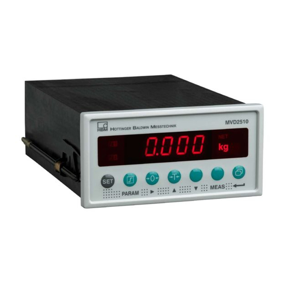
- Page 1 Operating manual Measurement amplifier for panel mounting MVD2510 A0125-4.0 en...
-
Page 3: Table Of Contents
MVD2510 Contents Page 1 Safety instructions ......... . - Page 4 MVD251 6.5.2 Load/Save in parameter set (PArA) ....6.5.3 Calibration (CAL) ........6.5.4 Limit values (Li1, Li2) .
-
Page 5: Safety Instructions
MVD2510 Safety instructions Appropriate use The MVD2510 with the connected transducers may be used for measurement and directly related control and regulation tasks, only. Any other use is not appropriate. To ensure safe operation, the transducer may only be used according to the specifications given in this manual. - Page 6 − The permissible relative humidity at 31 °C is 95 % (non condensing); linear reduction to 50 % at 40 °C. − It is safe to operate the MVD2510 system up to a height of 2000 m. − Mounting in an EMC-tested control cabinet with line filter (see page LEERER MERKER).
- Page 7 MVD2510 Product liability In the following cases, the protection provided for the device may be ad versely affected. Liability for device functionality then passes to the operator: − The device is not used in accordance with the operating manual. − The device is used outside the field of application described in this Chapter.
- Page 8 The CE mark is used by the manufacturer to declare that the product com plies with the requirements of the relevant EC directives (the Declaration of Conformity can be found at http://www.hbm.com/HBMdoc). On the module Meaning : Statutory waste disposal mark The electrical and electronic devices that bear this symbol are subject to the European Waste Electrical and Electronic Equipment Directive 2002/96/EC.
- Page 9 The supply connection, as well as the signal and sense leads, must be installed in such a way that electromagnetic interference does not adversely affect device functionality (HBM recommendation: ”Greenline shielding design”, downloadable from the Internet at http://www.hbm.com/Greenline Automation equipment and devices must be covered over in such a way that adequate protection or locking against unintentional actuation is provided (such as access checks, password protection, etc.).
- Page 10 MVD2510 Reconstruction and modifications HBM’s express consent is required for modifications regarding the MVD2510’s construction and safety. HBM does not take responsibility for damage resulting from unauthorized modifications. In particular, repair and soldering works on the boards are prohibited. If complete componentry is replaced use original HBM components, only.
-
Page 11: Scope Of Supply
1 terminal-strip plug (3 pins) for mains connection Introduction 3.1 General The MVD2510 amplifier for panel mounting (to DIN 43 700) enables measurements from strain-gauge transducers used for industrial weighing (not legal for trade) applications to be acquired and processed. -
Page 12: Block Diagram
Mounting 4.1 Read before mounting, factory setups Before installing the MVD2510 panel amplifier, check the parameters that have been adjusted at the factory, because the elements required for the selection of the analogue output signal (current/voltage output) are located on the board. -
Page 13: Change Factory Setups
MVD2510 4.2 Change factory setups Select analogue output signal To change the factory setup proceed as follows: 1 Slacken the four screws on the housing rear. 2 Carefully pull off to the back the housing rear and the board until the jumper arrangement is accessible. -
Page 14: Adjust Analogue Output Signal
4.2.2 Fuse replacement WARNING Disconnect the device from the mains supply before opening the MVD2510. To replace the fuse you have to take off the device rear as described above. Then, the fuse (230 V/100 mA; 115 V/200 mA) on the board will be accessible (lift off transparent cap). -
Page 15: Insert Unit Plug-In Strip
MVD2510 4.3 Insert unit plug-in strip The unit for display is defined by ready-made plug-in strips that are supplied with the device. 1 Remove the display’s plastics frame. 2 Insert the required strip into the appropriate cutout. 3 Re-install the plastics frame on the housing. -
Page 16: Install Amplifier On Control Cabinet
MVD2510 4.4 Install amplifier on control cabinet The MVD2510 has been designed for panel mounting according to DIN43 700. Install amplifier on panel: 1 Turn fastening bow downwards and remove it from housing. 2 Insert housing into panel cutout from the front. -
Page 17: Electrical Connection
MVD2510 Electrical connection 5.1 Connect voltage supply Compare the device’s mains voltage (specified on device rear) to the supply voltage. If they are not identical, contact your HBM representative. Transducer- Transducer- connection connection (15-pin D-plug) (15-pin D-plug) 9-pin terminal-strip socket 3-pin terminal-strip socket Fig. - Page 18 MVD2510 Mounting of the line filter: Make sure that the line filter is laid out flat on the inside of the control cab- inet and that the connecting cables are led directly to the filter’s input con- nectors. The filter is laid out flat on the control cabinet.
-
Page 19: Connect Transducers
MVD2510 5.2 Connect transducers The MVD2510 enables S/G full-bridge transducers to be connected via a 15-pin D-plug designated BU1 on the housing rear. See the below figures for the connection diagram. Six-wire connection BU 1 Transducer Meas. signal (+) connection-socket Bridge excitation voltage (−) - Page 20 MVD2510 Transducer 1 Route the two cable cores together as close as possible to the transducer Transducer 2 4 transducers maximum 80 ... 5000 Cable core colours: wh=white; bk=black; bu=blue; rd=red; ye=yellow; gn=green; gy=grey. Fig. 5.4: Connection of parallel−wired transducers...
-
Page 21: Analogue Output, Control Inputs/Outputs
MVD2510 5.3 Analogue output, Control inputs/outputs The analogue output signal is present at terminals 1 and 2 as voltage ("10 V) or current (0..."20 mA or +4...+20 mA). Use the plug bridges (jumpers) on the amplifier board to select current/voltage as described in chapter 3.2.1. -
Page 22: Adjustments And Operation
(panel amplifier and transducer) and to enable a first functional test for all components to be made. This section mainly describes the adaptation of the MVD2510 to the transducer type used. In addition, some errors are mentioned that typically occur during device start-up. - Page 23 MVD2510 D Connect the device to mains via an external switching device (mains switch). D The device makes a functional test and then enters measure mode. The factory setups are activated. Ex-works setting: The measurement range is set to a sensitivity of 2 mV/V and a display full−scale value of 10000 digits (see table on page 51).
-
Page 24: Device Operation And Survey Of Keyboard Functions
MVD2510 6.2 Device operation and survey of keyboard functions The operating concept differentiates between two types of key functions: − keys that are effective during the measurement mode and − keys that are effective in the programming mode. Each function key for Measure mode can be locked individually to prevent undesired key operation (see page 33). -
Page 25: Functions In Measure Mode
MVD2510 6.3 Functions in Measure mode If necessary, all keys/functions in Measure mode may be locked to prevent unauthorized manipulation. Meaning Permits to change from the Measure to the Programming mode (and vice versa) when pressed for about 2 sec. -
Page 26: Adjust Limit-Value Levels In The Measure Mode
MVD2510 6.3.1 Adjust limit-value levels in the Measure mode There are two possibilities for the selection of the limit-value level: a) Enter numerical value for limit-value levels (Li) Li1L (Limit value 1) The limit-value level entered last will be displayed. - Page 27 MVD2510 b) Accept signal present at the input as limit-value level Li1L (Limit value 1) The limit-value level entered last will be displayed. The signal present at the input will be MEAS displayed Confirm. The applied input signal is accepted as the limit level.
-
Page 28: Programming Mode
MVD2510 6.4 Programming mode In the Programming mode and 2 are flashing alternately. This Operating mode enables all amplifier setups required for your application to be made. The parameters are grouped and codes are used for the group names. Meaning of the keys: Change operating mode, select group (e.g. -
Page 29: Change From The "Measure" To The "Programming" Mode
MVD2510 6.4.1 Change from the ”Measure” to the ”Programming” mode D Press for approx. 2 s. The device changes from the ”Measure” to the ”Programming” mode if the password is 0000. This applies for the factory setup; dIAL will be dis- played. -
Page 30: Programming
MVD2510 6.4.2 Programming Operation in the Programming mode a) Select the value/parameter from a predefined table (Example dIAL-LAnG) D Use to select the group dIAL. D Use to select the parameter LAng D Press . The currently adjusted parameter will be displayed (e.g. -
Page 31: Change From The "Programming" To The "Measure" Mode
MVD2510 c) Accept transducer signal at defined load (Example CAL-rnGE) D Use to select CAL. D Use to select the parameter rnGE D Press . The measuring range in mV/V selected last will be displayed. MEAS D Press (display with the selected unit). -
Page 32: Information On Groups And Parameters
MVD2510 6.5 Information on groups and parameters Groups diAL Li.1 Li.2 I−O InFO PArA (Parameter (Calibra- (Limit (Addi- (Limit (Input/Out- (Dialog) tion) value 1) set) tional value 2) put) function) LAnG rEcA INdc FrEE A.SIG P_ _ Language Load Nominal... -
Page 33: Load/Save In Parameter Set (Para)
When changing from Measure to Program, the password is demanded (see page 29). The password guards against unauthorised MVD2510 operation. Parameters can only be changed when the valid password is entered. A change of pass- word is possible if the old password is known. -
Page 34: Calibration (Cal)
MVD2510 6.5.3 Calibration (CAL) Nominal value (INdc) The transducer’s full scale can be adjusted (Scale range "19999). A full scale value (e.g. 10.000 KN) is assigned to an input-signal range, e.g. 2 mV/V. Decimal point (dEc.P) The decimal-point position is changed. -
Page 35: Limit Values (Li1, Li2)
MVD2510 6.5.4 Limit values (Li1, Li2) The parameters for limit-value adjustment are grouped for each limit value. The limit values’ state is indicated on the display and transmitted via control outputs. The below figure illustrates the limit values’ function and the parameters:... - Page 36 MVD2510 Level (PEGL) The level is adjusted in display units (e.g. 2.000 kg). Hysteresis (HYSt) The hysteresis is entered to prevent a ”fluttering” of the limit-value switch when the switching threshold is reached. The hysteresis results from the differential between switch-on and switch-off threshold.
-
Page 37: Inputs And Outputs (I_O)
MVD2510 6.5.5 Inputs and outputs (I_O) This menu enables the setups required for the MVD2510 input signal, the analogue output and the control contacts to be made. Output signal(A.SIG) The output signal weighting: Gross value groS Net value Analogue signal (U_I) Note Use jumpers on the amplifier board to select current output or voltage output. -
Page 38: Additional Function (Info)
Control contact 1..2 (rE.1 /rE.2) You have contacts available on terminals 6 and 7 on the terminal strip socket (9−pole) for the control of some MVD2510 functions. The control contacts may be assigned as desired. The factory setup for the contacts is ”No func- tion”. -
Page 39: Example
MVD2510 Example The below example uses a measurement task to show the device functions and the required setups. Measurement task: Filling a container Containers are filled by weighing on a platform weighing machine. The plat- form is fitted with a load cell with a measurement range of 100 kg (corres- ponding to 2 mV/V). - Page 40 MVD2510 Explanation of symbols Select number Group old setting Parameter new value Change value Press 2 sec Password query (see page 29) Dialogue CodE Password 0000 1510 A0125-4.0 en...
- Page 41 MVD2510 b.ZEr Zero key FrEE LOCKED b.tAr Tare key LOCKED FrEE Changing group Parameter set Au.St Zero/Tare value A0125-4.0 en...
- Page 42 MVD2510 Changing group Calibration INdc Nominal value 10000 8000 dEc.P dEc.P Dec.point 0000 0000 00.00 dEc.P StEP Digit step 0100 0001 A0125-4.0 en...
- Page 43 MVD2510 nuLL Zero value Load removed from weighing machine 0.135 Zero value in mV/V (old) MEAS 00.00 Full scale value in kg (new) Zero value in mV/V (new) 0.200 Measuring range rnGE Weighing machine loaded with partial load of 50 kg Measuring range in mV/V (old) 2.000...
- Page 44 MVD2510 Filter dEc.P FILt 2.0Hz Changing group Vimit value 1 dEc.P FrEE Enable/Lock A0125-4.0 en...
- Page 45 MVD2510 qUEL Gross/Net GROSS Switching direction Limit value 1 Li.Le 10.00 52.00 A0125-4.0 en...
- Page 46 MVD2510 dEc.P dEc.P qUEL HYSt Hysteresis 0000 0.50 Control cantacts LoGc output logic Change via Lim key bu.Li LOCKED FrEE A0125-4.0 en...
- Page 47 MVD2510 Changing group Limit value 2 dEc.P FrEE Enable/Lock dEc.P dEc.P qUEL Sour Gross/Net GROSS Switching direction A0125-4.0 en...
- Page 48 MVD2510 PEGL Limit value 2 00.00 02.00 HYSt Hysteresis 0000 00.50 Control cantacts LoGc output logic A0125-4.0 en...
- Page 49 MVD2510 bu.Li Change via Lim key LOCKED FrEE Changing group Input/Output dEc.P A.SIG Outpit signal GROSS dEc.P NOTE Analog signal Use plug bridges on the amplifier board to select current output or voltage 0-20mA output. Refer to page 14 for a 4-20mA description of the procedure.
- Page 50 MVD2510 tESt Input signal CAL.S MES.S rE.1 Control contact 1 - - - - tArA Remote control Press 2 sec A0125-4.0 en...
-
Page 51: Displays And Ex-Works Settings
MVD2510 Displays and ex-works settings Display Meaning Factory setup dIAL Operating dialogue LanG Dialog-Language dEut CodE Password 0000 b.Li Limit value key FrEE b.ZEr Zero key FrEE b.tAr Tare key FrEE b.SIG Signal key FrEE PArA Parameter set rEcA Parameter set or factory setup... -
Page 52: Error Messages
MVD2510 Input/Output signals A.SIG Source of Output signal GROSS Analog signal 10 V tEST Input signals MES.S rE.1 Control contact 1, 2 Remote control InFO Additional functions Firmware Error messages Error message Reason Remedy LOCKED The specified value cannot Enable limit-value change be changed. -
Page 53: Keyword Index
MVD2510 Keyword index Error message, 23 Example for measurement, 39 Accept transducer signal, 31 Adaptation to transducer, 39 Additional function , 38 Factory seting, 51 Adjust limit−value levels, in the Measure mode, 26 Factory setup, 12, 22 load/save, 33 Analogue output, Current, Voltage, 14, 21... - Page 54 MVD2510 Programming mode, 29, 30, 31 Measure mode, 29, 31 Measure mode , 25 Remote control , 38 Net, 25, 37 S/G full bridges, Connect, 19 Net value, 35 Select language , 32 Nominal value , 34 Select parameters, 30 SET, 25, 28 Start−up , 22...
- Page 55 MVD2510 A0125-3.0 en...
- Page 56 All product descriptions are for general information only. They are not to be under stood as a guarantee of quality or durability. Hottinger Baldwin Messtechnik GmbH Im Tiefen See 45 S 64293 Darmstadt S Germany Tel. +49 6151 803−0 S Fax: +49 6151 803−9100 Email: info@hbm.com S www.hbm.com measure and predict with confidence...
Need help?
Do you have a question about the MVD2510 and is the answer not in the manual?
Questions and answers