Sign In
Upload
Download
Table of Contents
Contents
Add to my manuals
Delete from my manuals
Share
URL of this page:
HTML Link:
Bookmark this page
Add
Manual will be automatically added to "My Manuals"
Print this page
×
Bookmark added
×
Added to my manuals
Manuals
Brands
HBM Manuals
Amplifier
AE101
Operating manual
HBM AE101 Operating Manual
Clip electronic clip ig
Hide thumbs
1
Table Of Contents
2
3
4
5
6
7
8
9
10
11
12
13
14
15
16
17
18
19
20
21
22
23
24
25
26
27
28
29
30
31
32
33
34
35
36
37
38
39
40
41
42
43
44
45
46
47
48
49
50
page
of
50
Go
/
50
Contents
Table of Contents
Bookmarks
Table of Contents
Table of Contents
Safety Instructions
1 Application
2 Mounting / Dismounting
3 Connection
Measuring Amplifiers AE101, AE301, AE501
GR201, EM201, EM201K2, TS101 Additional Units
NT101A, NT102A Power Supply
4 Setup
AE101 Measuring Amplifiers
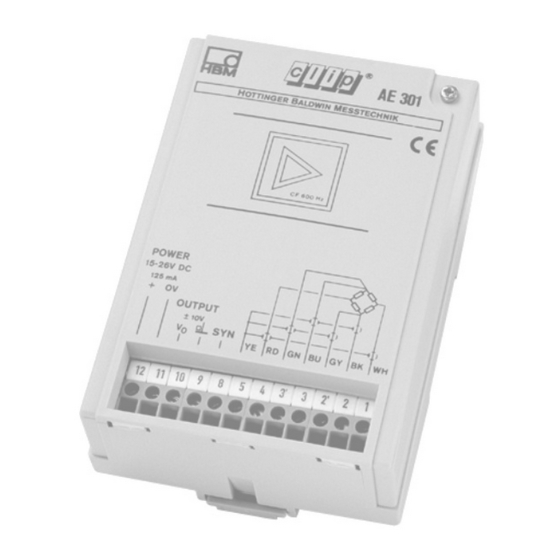
AE301 Measuring Amplifier
AE501 Measuring Amplifier
GR201 Double Limit-Value Switch
EM201 / EM201K2 Output Stage
5 TS101 Automatic Tare and Store Unit
General
Function
Taring
Store Unit
Connection
Voltage Supply
Inputs / Outputs
Control Inputs / Control Output
Adjustment
Factory Setup
Tare Unit Adjustment
Store Unit Adjustment
Zero-Point Balance
Component Position Diagram
6 Safety Barriers
7 Clip Ig
8 Dimensions
9 Specifications
10 Accessories
Advertisement
Quick Links
1
Application
2
Measuring Amplifiers Ae101, Ae301, Ae501
3
Ae101 Measuring Amplifiers
4
Ae301 Measuring Amplifier
5
Adjustment
Download this manual
Operating manual
Clip Electronic
Amplifier for installation
onto mounting rails
Clip IG
Industrial amplifier in
cast housing
A0114-6.3 en
Table of
Contents
Previous
Page
Next
Page
1
2
3
4
5
Advertisement
Table of Contents
Need help?
Do you have a question about the AE101 and is the answer not in the manual?
Ask a question
Questions and answers
Related Manuals for HBM AE101
Amplifier HBM AE301 Operating Manual
Clip electronic clip ig (50 pages)
Amplifier HBM AE501 Operating Manual
Clip electronic clip ig (50 pages)
Amplifier HBM SCOUT55 Operating Manual
Measuring amplifier in desktop housing (64 pages)
Amplifier HBM MP85 Operating Manual
Two-channel amplifier (56 pages)
Amplifier HBM ME50S6 Operating Manual
4.8 khz cf measuring amplifier (64 pages)
Amplifier HBM ME50S6 Operating Manual
4.8 khz cf measuring amplifier (28 pages)
Amplifier HBM RM4220 Operating Manual
S.g. (44 pages)
Amplifier HBM MP85A Operating Manual
Twin-channel-amplifiers (84 pages)
Amplifier HBM QuantumX MX1615B Operating Manual
(220 pages)
Amplifier HBM espressoDAQ DQ401 Operating Manual
Measuring amplifier (146 pages)
Amplifier HBM MVD2510 Operating Manual
Measurement amplifier for panel mounting (56 pages)
Amplifier HBM PAD4002A Operating Manual
Digital transducer electronics (102 pages)
Amplifier HBM MVD2555 Operating Manual
Measuring amplifier for instrument panel mounting (68 pages)
Amplifier HBM MVD2555 Operating Manual
Measuring amplifier for instrument panel mounting (69 pages)
Amplifier HBM MX840B Operating Manual
Quantum x family (224 pages)
Amplifier HBM MGC Operating Manual
With ab12 (288 pages)
This manual is also suitable for:
Ae301
Ae501
Table of Contents
Print
Rename the bookmark
Delete bookmark?
Delete from my manuals?
Login
Sign In
OR
Sign in with Facebook
Sign in with Google
Upload manual
Upload from disk
Upload from URL


Need help?
Do you have a question about the AE101 and is the answer not in the manual?
Questions and answers