Table of Contents
Advertisement
Advertisement
Table of Contents

Related Manuals for HBM MP85


Summary of Contents for HBM MP85
- Page 1 Operating manual Two−channel Amplifier Module MP85 A0897-3.4 en...
-
Page 3: Table Of Contents
..........1.3 Valuable information about PME MP85 documentation . - Page 4 PME-MP85 6 Communication with the control system ..... . 6.1 Timing of the test operations .......
-
Page 5: Safety Instructions
18 to 30 V. General dangers of failing to follow the safety instructions The MP85/MP85DP module corresponds to the state of the art and is fail−safe. The device may give rise to further dangers if it is inappropriately installed and operated by untrained personnel. - Page 6 PME-MP85 Any risk of residual dangers when working with the MP85/MP85DP is pointed out in this introduction by means of the following symbols: WARNING Symbol: Meaning: Dangerous situation Warns of a potentially dangerous situation in which failure to comply with safety requirements can result in death or serious physical injury.
- Page 7 Conversions and modifications The MP85/MP85DP module must not be modified from the design or safety engineering point of view except with our express agreement. Any modification shall exclude all liability on our part for any resulting damage.
-
Page 8: Introduction
D standard ribbon cable, 10−pin, grid 1.27 mm 1.2 General The MP85/MP85DP module from the PME product line is a two−channel measuring amplifier suitable for connecting the transducers of a great variety of technologies. In the case of the MP85DP, there is also a Profibus interface available for CAN-Interface. -
Page 9: Valuable Information About Pme Mp85 Documentation
The PME Assistant is the sole means of parameterizing and setting up the MP85/MP85DP module (described in the Online Help). To do this you need an LPT → CAN or USB → CAN interface converter, that has to be ordered separately (1−PMESETUP; 1−PMESETUP-USB). -
Page 10: Commissioning
To prepare the MP85 measurement system for a measurement task, the following conditions must be met or the relevant steps taken: • You need a PME module MP85 or MP85DP and the PME Assistant, including software • The hardware must be configured (transducer, device, PC with the software) (from Page 16) •... -
Page 11: Philosophy Of Operation
PME-MP85 2.1 Philosophy of operation 2.1.1 Settings on the device The display of the MP85/85DP shows you the measured value and status information. The device is actually set up by means of the “PME Assistant” software (described in Online Help). - Page 12 OK • Started a process has been started and not yet finished 3. Status of the digital inputs and outputs The MP85 has 5 inputs and 8 outputs. The MP85DP has 1 input and 4 outputs. • Input set, not set •...
- Page 13 PME-MP85 5. MMC-DisplayState (MMCState) Display Explanation notinuse No data storage on MMC with any other display: data storage on MMC no MMC There is no MMC in the device Init... The MMC is initialized automatically after insertion SET ³ STOP MMC ready for storing.
-
Page 14: Overview Of All Groups And Parameters
MMC using the PME Assistant. MAINGRP Address PrgVers − OutpR. ms SrNo Down MAINGRP HW vers Load MMC MAINGRP We recommend to format the MMC from time to time for optimizing MMC access times. with back to Group MAINGRP A0897−3.4 en HBM... -
Page 15: Configuring Parameters On The Device
0 − 39 ↓ ↑ OutpR. ms back Parameter values back MAINGRP MAINGRP Select Parameters − ↓ ↑ Flashes if the parameter value can be edited Print Confirm your Input +/- = − 2sec Back to measuring mode: A0897−3.4 en HBM... -
Page 16: Configuring The Hardware
PME-MP85 2.2 Configuring the hardware 2.2.1 Voltage supply / Transducer • Connect the power supply cable and the transducer to the module (Chapters 5.3 and 5.4). CAUTION Be sure to comply with the safety instructions! • Activate the power supply. -
Page 17: Connecting The Can Adapter (Lpt And Usb)
Alternatively you can attach this power supply cable between the keyboard connector and the relevant PC socket. • Attach the CAN connector cable to the MP85 to the adapter. • Activate the PC. Connecting USB to CAN First install the PME Assistant. -
Page 18: Installing The Pme Assistant Software
PME-MP85 2.3 Installing the PME Assistant software 2.3.1 System requirements To operate the PME Assistant software you need a PC with the following prerequisites: − min. processor requirement, Intel Pentium 400 MHz or equivalent − Windows 95 or higher, Windows NT Version 4.0 or later, Service Pack 3, Windows 2000 −... -
Page 19: Starting The Software And Setting Up
PME-MP85 2.4 Starting the software and setting up Interface mode The factory settings of the interface CAN bus scan for connected PME modules Opens the Setup window Fig. 2.1: Startup window 2.4.1 Using the LPT interface • Start the PME Assistant program and in the startup window, enter the interface details. - Page 20 <CAN−ID> dropdown list box in the Devices area. 6. Select a module and click on <SET>. This opens the Setup window (see Online Help). You can now use the PME Assistant software to set up the MP85. This is described in the Online Help. A0897−3.4 en...
-
Page 21: Using The Usb Interface
<CAN-ID> dropdown list box in the Devices area. 6. Select a module and click on <SET>. This opens the Setup window (see Online Help). You can now use the PME Assistant software to set up the MP85. This is described in the Online Help. A0897−3.4 en... -
Page 22: Switch Settings / Replacing The Battery
PME-MP85 Switch settings / Replacing the battery Modifying the supply voltage for active encoders Use switch S1 to toggle the supply voltage for active encoders between the internal 5V supply and the external 24V supply. This is the only changeover that the housing has to be open for. - Page 23 PME-MP85 Replacing the battery The MP85 has a realtime clock which is fed by a type CR2032 lithium battery. This can be removed from the battery holder and replaced at the point shown in Fig. 3.3. The battery should be replaced approx. every 5 years.
-
Page 24: Mp85/Mp85Dp Mounting/Disassembly (Schematic Diagrams)
PME-MP85 MP85/MP85DP mounting/disassembly (schematic diagrams) Fig. 4.1: Mounting on a support rail Fig. 4.2: Disassembly CAUTION The support rail must lie on protective-conductor potential A0897−3.4 en... -
Page 25: Linking Several Modules
Fig. 4.3: Connecting the ribbon cable Up to four MP85/MP85DP modules can be linked via a ribbon cable. This cable ensures local connection of the supply voltage, the CAN bus and synchronization of the carrier frequency between modules. -
Page 26: Connections
PME-MP85 Connections WARNING Before starting the device, read the safety instructions. 5.1 MP85 functional overview Local connection of CAN bus, supply voltage and synchronization between modules Screw terminal 1: Voltage supply and CAN bus, synchronization LED 1 Screw terminal 2: (same assignment as... -
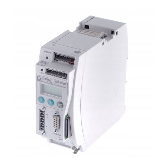
Page 27: Mp85Dp Functional Overview
PME-MP85 5.2 MP85DP functional overview Local connection of CAN bus, supply voltage and synchronization between modules Screw terminal 1: Voltage supply and CAN bus, synchronization LED 1 Screw terminal 2: (same assignment as screw terminal 1) LED 2 CAN adapter for PC/laptop connection,... -
Page 28: Supply Voltage And Control Inputs/Outputs
PME-MP85 5.3 Supply voltage and control inputs/outputs Four (MP85) or three (MP85DP) connectable screw terminals are available for connecting the supply and the control inputs/outputs. Connecting the voltage supply: WARNING The MP85/MP85DP module must be connected to an external supply voltage of 18−30 V (24 V D The wire ends of the voltage supply must be provided with end sleeves for strands. -
Page 29: External Supply Voltage For Control Outputs
• at screw terminal 3: control outputs 1 − 4 • at screw terminal 4: control outputs 5 − 8 (MP85 only) Control outputs must be supplied with an external voltage (ground and 24V) via screw terminal 3. -
Page 30: Transducer
PME-MP85 5.4 Transducer 2 transducers can be independently connected at screw terminals 5 and 6. 5.4.1 Transducers with carrier frequency excitation In “carrier frequency amplifier” mode, the following transducer types can be connected: MP85 MP85DP Screw terminals 5 and 6... - Page 31 Cable core colors: WH= white; BK= black; BU= blue; RD= red; YE= yellow; GN= green; GY= gray Fig. 5.4: Transducer connection in four-wire technology NOTE To connect the transducers, use standard cable from HBM or another shielded, low-capacitance measurement cable. Connect the shield of each transducer cable via the shortest possible lead (t5 cm) and a blade connector (4.8 mm;...
- Page 32 PME-MP85 Synchronization: Synchronization is advisable for carrier-frequency fed transducers if D the transducer cables of several devices are installed side by side D the measuring points are close together and unshielded Synchronisation prevents carrier frequency differences leading to disturbing superpositions.
-
Page 33: Active Encoders
PME-MP85 5.4.2 Active encoders In “incremental encoder, SSI transducer or direct voltage encoder” mode, the following transducer types can be connected: MP85 MP85DP Pulse counter, incremental transducer (symmetric signals) Ground Ground Measurement signal F1 (+), 0° f1, 0 f1, 0 Measurement signal F1 (−), 0°... - Page 34 Switch S1 is used to toggle between an internal and an external supply. The device has to be opened to do this. (see Chapter 3). • Transducer supplied from the MP85/MP85DP: Transducer supply voltage 5V "10 %, 150 mA max. (for both channels together).
-
Page 35: Can Interface
PME-MP85 5.5 CAN interface The CAN bus is connected via screw terminal 1. A maximum of 32 CAN nodes can be connected in one bus segment (under CANopen specification). The CAN bus needs a terminating resistance of 120 Ω in the first and last bus nodes. -
Page 36: Profibus Interface (Mp85Dp Only)
PME-MP85 5.6 Profibus interface (MP85DP only) On the front panel of the MP30DP is a 9-pin D-sub connection socket for the Profibus connection. RS485-RTS RS485-A RS485-B Vcc (5V) Profibus connection socket Fig. 5.9: Profibus connection in accordance with standard Installation: •... -
Page 37: Communication With The Control System
PME-MP85 Communication with the control system All the diagrams relate to a positive logic. 6.1 Timing of the test operations a.) Storing curves and results without data loss The below diagrams apply, if you choose the “without data loss” storage me- thod and want to save curves and/or results on the MMC or externally via CAN. - Page 38 PME-MP85 b.) Process optimized storage of curves and results The below diagrams apply, if you choose the “Process optimized storage” sto- rage method and want to save curves and/or results on the MMC or externally via CAN. In contrast to the “Storing without data loss” method, the READY si- gnal can be reset to 1 even if the device is not yet ready to save new data.
-
Page 39: Transducer Test
PME-MP85 6.2 Transducer test Transducer test timing diagram min. 5 ms Input Transducer test Output transducer test result typically 10 ms 6.3 Zero balance Zero balance timing diagram min. 5 ms Inputs Zeroing Input START Settling time e.g. for 100 Hz filter: 20 ms... -
Page 40: Parameter Set Switching
PME-MP85 6.4 Parameter set switching Inputs Switchover occurs when the level changes Load parameter set bit 0 − bit 4 Output Busy typically 500 ms Bit 4 Bit 3 Bit 2 Bit 1 Bit 0 Active parameter set Factory settings... -
Page 41: Error Messages/Operating Status (Led
This can be a one-off read error, the Flash EOROM. please repeat the operation. If the error occurs again, please contact HBM Service. An error occurred at the CAN bus Check whether there are termi- CAN bus error nating resistances or whether a channel is faulty. - Page 42 The LEDs show the operating status (ready to take measurements, overflow etc.) of the device. With the MP85DP, however, the Profibus status is displayed instead of the CAN status (as is the case with the MP85). LED 1 LED 2...
-
Page 43: Specifications
24; Potential separation from measuring system (typically 500 V Permitted supply voltage range 18...30 Power consumption MP85, typically MP85DP, typically MP85 / MP85DP, max. Backing battery for realtime clock Years (CR2032), typical lifetime Operating modes, independently adjustable for both channels Carrier-frequency amplifier Carrier frequency 4.8 "1 %... - Page 44 PME-MP85 Nomin Phase Rise Over- −1dB −3dB (rated) delay time shoot (Hz) (Hz) value (ms) (ms) fc (Hz) 1200 0.450 0.290 1000 1400 0.550 0.260 0.860 0.510 1.11 Measurement frequency range, Measurement frequency range, 2.13 adjustable adjustable 4.24 Low pass 4th order with Bessel Low pass 4th order with Bessel 8.36...
- Page 45 PME-MP85 Incremental encoder Attachable process quantity transducer Incremental encoder (up/down counter with zero index signal) Voltage supply 5 V, max. 150 mA or 24 V max. 300 mA Dual-channel mode Time division multiplex method Inputs (F1 ("), F2 ("), Ix ("))
- Page 46 1 ... 100 Adjustment accuracy Digit Response time, typically (fc=1000 Hz) Control outputs Number 4 (MP85DP) / 8 (MP85) Nominal voltage, external power supply Permitted supply voltage range 10 − 30 Maximum output current per output Short-circuit current, typically . = 24 V, R t 0.1 Ohm)
- Page 47 PME-MP85 Multimedia card (memory card on Flash base) Usable types 8, 16, 32, 64 bytes Data transmission rate, typically K-byte File system Display Type Two line, 8 character alphanumeric, LCD Keyboard Touch-sensitive keypad with three keys Temperature range Nominal temperature range 0 −...
- Page 48 PME-MP85 Specifications for analysis unit Max. number of data triples 4000 (auto. data reduction) (channel x); (channel y); (time) Sampling rate, max. 2400 Analysis Max. number of analysis windows Type of window Oblique or straight Analysis methods per window Plot analysis...
-
Page 49: Declaration Of Conformity
PME-MP85 Declaration of conformity A0897−3.4 en... - Page 50 PME-MP85 A0897−3.4 en...
-
Page 51: Keyword Index
PME-MP85 Keyword index active encoders, 22 , 33 DC voltage source, 33 active parameter set, 40 declaration of conformity, 49 digital input, 28 digital inputs, 12 digital output, 28 CAN bus, 15 , 26 , 27 , 35 connecting, 26 , 27... - Page 52 PME-MP85 screw terminal assignment, 28 self−test, 16 parameters, 14 supply voltage, 28 configuring, 15 synchronization, 26 , 27 , 32 PLC connection, 29 PME Assistant, 18 power failure, 28 process status, 12 terminating resistance, 22 , 35 Profibus interface, 36...
- Page 53 PME-MP85 A0897−3.4 en...
- Page 54 PME-MP85 A0897−3.4 en...
- Page 56 Hottinger Baldwin Messtechnik GmbH Postfach 10 01 51, D-64201 Darmstadt Im Tiefen See 45, D-64293 Darmstadt Tel.: +49/61 51/ 8 03-0; Fax: +49/61 51/ 8039100 E−mail: support@hbm.com www.hbm.com A0897−3.4 en...
Need help?
Do you have a question about the MP85 and is the answer not in the manual?
Questions and answers