
Subscribe to Our Youtube Channel
Related Manuals for HBM MVD2555


Summary of Contents for HBM MVD2555
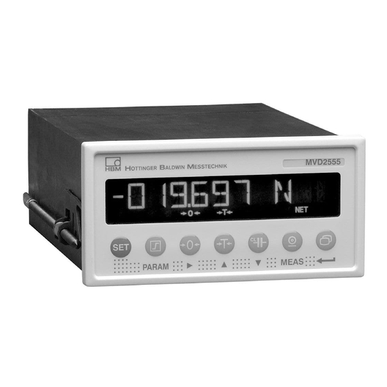
- Page 1 Operating manual Measuring amplifier for instrument panel mounting MVD2555 A0104−6.0 en...
-
Page 3: Table Of Contents
MVD2555 Contents Page Contents Safety instructions ......... . . - Page 4 MVD2555 5.5.5 Calibration (CALIBR.) ....... 5.5.6 Limit switches 1 ... 4 (LIMITVAL.1 ... 4) .
-
Page 5: Safety Instructions
MVD2555 Safety instructions Appropriate use The MVD2555 with the connected transducers may be used for measurement and directly related control and regulation tasks, only. Any other use is not appropriate. To ensure safe operation, the transducer may only be used according to the specifications given in this manual. - Page 6 − The permissible relative humidity at 31 °C is 95 % (non condensing); linear reduction to 50 % at 40 °C. − It is safe to operate the MVD2555 system up to a height of 2000 m. − Mounting in an EMC-tested control cabinet with line filter (see page 16).
- Page 7 MVD2555 In the following cases, the protection provided for the device may be ad versely affected. Liability for device functionality then passes to the operator: − The device is not used in accordance with the operating manual. − The device is used outside the field of application described in this Chapter.
- Page 8 The CE mark is used by the manufacturer to declare that the product com plies with the requirements of the relevant EC directives (the Declaration of Conformity can be found at http://www.hbm.com/HBMdoc). On the module Meaning : Statutory waste disposal mark The electrical and electronic devices that bear this symbol are subject to the European Waste Electrical and Electronic Equipment Directive 2002/96/EC.
- Page 9 The supply connection, as well as the signal and sense leads, must be installed in such a way that electromagnetic interference does not adversely affect device functionality (HBM recommendation: ”Greenline shielding design”, downloadable from the Internet at http://www.hbm.com/Greenline Automation equipment and devices must be covered over in such a way that adequate protection or locking against unintentional actuation is provided (such as access checks, password protection, etc.).
- Page 10 MVD2555 HBM’s express consent is required for modifications regarding the MVD2555’s construction and safety. HBM does not take responsibility for damage resulting from unauthorized modifications. In particular, repair and soldering works on the boards are prohibited. If complete componentry is replaced use original HBM components, only.
-
Page 11: Introduction
MVD2555s (at a common RS485 bus) All the commands needed for device setup over the serial interface and for querying the measured values are listed and described in a separate Operating Manual document “Operating the MVD2555 by Computer” . A0104−6.0 en... -
Page 12: Block Diagram
MVD2555 2.3 Block diagram Measure Zero Cal. Parameter memory Data set 1...8 Control signals 127,533 KN Optical coupler LVDT RS-232 or 5 outputs/ RS-485 6 inputs Fig. 2.1 MVD2555 block diagram A0104−6.0 en... -
Page 13: Mounting
MVD2555 Mounting 3.1 Pre-installation notes, factory settings Before installing the device, check the parameters set at the factory, as the elements for selecting the analogue output signal (current/voltage output) and for setting synchronization, are located on the motherboard. Important The device must be mounted in an EMC-tested control cabinet with line filter (see page 16). -
Page 14: Changing The Factory Settings
(230 V/T63mA L; 115 V/T125mA L) will then be accessible on the motherboard (see Fig. 3.1). 3.3 Installing the amplifier in a panel−frame The MVD2555 is designed to be installed in panel−frames, in accordance with DIN43700. Installation steps: D Remove the fastening strap. - Page 15 MVD2555 D Hang up the fastening strap on both sides and fasten it to the cutout with the two threaded rods. D Then connect the supply voltage and the transducer, as shown in chapter 3. partial section, front panel +0.7...
-
Page 16: Connections
4.1 Connecting the voltage supply Check that the mains voltage of the device (details on the back of the device) matches the supply voltage. If this is not the case, please contact the appro- priate HBM branch or HBM representative. interface port RS485... - Page 17 MVD2555 Mounting of the line filter: Make sure that the line filter is laid out flat on the inside of the control cab- inet and that the connecting cables are led directly to the filter’s input con- nectors. The filter is laid out flat on the control cabinet.
-
Page 18: Connecting Transducers
MVD2555 4.2 Connecting transducers The following transducer types can be connected to the device: D S.G. full and half bridge transducers D Inductive full and half bridge transducers D Potentiometric and piezoresistive transducers D LVDT (Linear Variable Differential Transformer) The connection is made using a 15−pin D−Sub connector on the back panel of the housing, labelled BU1 (cable end connector: DB-15P, Order No. -
Page 19: Analogue Output
Note Use HBM standard cable for transducer connection. When using other screened, low‐capacitance cable types connect the transducer cable screen to the plug housing according to the HBM Greenline information, thus ensuring optimum EMC protection. 4.3 Analogue output The analogue output signal is available as voltage ("10 V) or as current ("20 mA or 4 ... -
Page 20: Control Inputs / Outputs
MVD2555 Á Á Á Á Á Á Á Á Á Á Á Á Á Á Á Á Á Á Á Á Á Á Á Function Function Á Á Á Á Á Á Á Á Á Á Á Á Á Á Á Á... -
Page 21: Synchronization
MVD2555 MVD2555 Relay max. 0.5 A max. 0.5 A 24 V* 24 V* 0 V* 0 V* Fig. 4.6: Output assignments WARNING The control inputs and outputs on the terminal‐strip socket (9 pins) are elec trically isolated by optocouplers. The control outputs must be supplied with an external DC voltage (ground and 24 V) and must have protective separation from the mains (safety extra low voltage as per EN 61140 and IEC 61140 re... -
Page 22: Setting The Reading Angle Of The Display
Chapter 4.4.11. When connecting a computer, it is possible to enter into dialogue with the MVD2555. You can use control commands to make all the device settings and query the measured values. An overview of the interface commands has been compiled in another part of the Operating Manual “Operating the MVD2555... -
Page 23: Setting Up And Operation
(panel−frame amplifier and transducer) are listed below, so that you can carry out an initial function test of all components. The description basically covers adapting the MVD2555 to the transducer type to be used. We also warn about certain errors which can typically occur during commissioning. - Page 24 MVD2555 D To get from measuring mode to device setup mode, press for about 2 s. ”DIALOG” will appear in the display. D Follow the examples given below to adjust the device to the connected transducer type. Transducer types: S.G. force transducer:...
- Page 25 MVD2555 Key to symbols select number Group old setting Parameter new value change value MEAS. MODE Press for 2 sec Programming mode DIALOG Language Language ENGL DEUTSCH Press twice ADAPTION transducer adaption continued on next page A0104−6.0 en...
- Page 26 MVD2555 S.G. Inductive Piezoresistive Potentiometric force transducer displacement transducer transducer transducer (= factory settings) TRANSD. TYPE Transducer type LVDT FULL BRG. HALF BRG. HALF BRG. HALF BRG. EXCITATION Setting the excitation voltage 2.5 VOLT 1.0 VOLT 2.5 VOLT 1.0 VOLT...
- Page 27 MVD2555 S.G. Inductive Piezoresistive Potentiometric force transducer displacement transducer transducer transducer (= factory settings) Measured quantity unit UNIT ....NOM. VALUE Nominal value input ....20000 kN 20000 mm 30000 bar 10000 mm press four times (Skip decimal point, digit step and zero value) dEc.P...
- Page 28 MVD2555 Switch to measuring mode Press for 2 s SAVE The settings are saved in parameter set 1 and the device switches to measuring mode. You can now run an initial function test. CAUTION The settings are only saved buffered against mains failure when they have been saved under one of the parameter sets.
-
Page 29: Control Concept And Functional Overview
MVD2555 5.2 Control concept and functional overview The control concept makes a distinction between two types of button functions: − Buttons that are operative during measuring mode and − Buttons needed for programming. Measured value display, parameter presentation Button Measuring mode... -
Page 30: Button Functions In Measuring Mode
MVD2555 5.3 Button functions in measuring mode Meaning Switch from measuring operating mode to programming (and vice versa) by pressing for approx. 2 s. Set the limit values LV1 ... 4 (see from Page 31) The additional parameters of the limit switches such as hysteresis, direction etc., are unchanged. -
Page 31: Querying And Setting Limit Values In Measuring Mode
MVD2555 5.3.1 Querying and setting limit values in measuring mode You have several options available when choosing the limit values (in measuring mode): a: Numerical value entry for limit values b: Apply input signal as limit value c: Fast search (keep arrow keys pressed for several seconds) MEAS. -
Page 32: Button Functions In Programming Mode
MVD2555 5.4 Button functions in programming mode In this operating mode, you can make all the settings for using the amplifier in your application. The parameters are collected into groups. Significance of the buttons: Change operating mode, select group (e.g. CALIBR.) Parameter selection (e.g. -
Page 33: Changing From "Measuring" Operating Mode To "Programming
MVD2555 5.4.1 Changing from ”Measuring” operating mode to ”Programming” If the password is 0000 (factory setting), the device changes the operating mode. Press for 2 s If a password has already been entered (and is not DIALOG 0000), CODE appears, that is, the password has to be entered if you wish to continue ”Programming”. -
Page 34: Programming
MVD2555 5.4.2 Programming Typical programming mode operations Select the value/ Enter a numerical value as a Apply a signal produced by the parameter from a given table parameter transducer when a defined load- (example DIALOGUE LAN- (example CALIBR./ ing occurs. -
Page 35: Switching From "Programming" Mode To "Measuring
MVD2555 5.4.3 Switching from ”Programming” mode to ”Measuring” When the parameters are changed, you are asked whether the modified parameters are to be saved power fail safe. Press for 2 s SAVE Not saved power fail safe SAVE DONE Saved power fail safe in... -
Page 36: Overview Of All Groups And Parameters
5.5 Overview of all groups and parameters Groups DIALOG PARAM. SET ADAPTATION CALIBR. LIMITVAL.1 ... 4 PV STORE IN/OUT ADD. FUNCT. LANGUAGE RECALL TRANSDUCER UNIT ENABLE ENABLE SOURCE UA PASSWORD SAVE ? EXCITATION NOM. VALUE SOURCE PVS1 MODE UA SERIAL NO. DEC. -
Page 37: Setting All Parameters
5.5.1 Setting all parameters 2sec Password Meas. Value 00000 Groups adaptation PARAM. SET +0000 CODE DIALOG PARAM DEUTSCH PARAM Enter password PARASET 1 _ _ _ _ ENGLISH PARASET 2 press twice LANGUAGE FRANCAIS PARASET 3 RECALL ITALIANO PARASET 4 ESPANOL PARASET 5 PARASET 6... - Page 38 groups Parameter set PV STORE CALIBR. ADAPTATION LIMIT VALUE 1...4 FULL BRG. PARAM HALF BRG. PARAM PARAM LVDT TRANSDUCER 2.5 VOLT UNIT ENABLE EXCITATION 1.0 VOLT 4 mV/V GROSS.VALUE INPUT NOM. VALUE SOURCE 40 mV/V +010 000 V NET VALUE 400 mV/V PVS1 MAX PVS2 MIN...
- Page 39 Groups LIMITVAL.1...4 PV STORE IN/OUT ADD. FUNCT. PARAM PARAM PARAM GROSS.VALUE NET VALUE 9600 BAUD PVS1 MAX SOURCE UA PVS OFF 4800 BAUD ENABLE PVS2 MIN PVS ON SERIAL NO. 2400 BAUD PVS3 PP 1200 BAUD 600 BAUD 10 VOLT BAUDRATE MODE UA 300 BAUD...
-
Page 40: Dialogue
When switching from Measuring to Programming, you are asked for a password (see Page 33). The password prevents unauthorized operation of the MVD2555. Parameters can only be changed if the valid password is entered. The password can only be changed if the old password is known. -
Page 41: Load/Save In Parameter Set (Param. Set)
MVD2555 5.5.3 Load/Save in parameter set (PARAM. SET) The current device amplifier settings can be saved power fail safe in eight parameter sets and later queried. When switching from the programming operating mode to measuring mode, you will be asked whether or not the change is to be saved. This is described in Chapter 5.4.3 . - Page 42 MVD2555 AUTOCAL: Depending on the application and on the stability requirement, you can start an autocalibration cycle. This lets you correct zero point and full scale value drift and the long−term constancy of the measuring amplifier. Possible settings: Autocalibration switched on...
- Page 43 MVD2555 MOTION CNT (Motion count) To activate the motion count, you must set the number of measurements. During these measurements, the measured value must fall within the given tolerance for ”standstill” to be reported. (for sampling rate, see table on Page 42).
-
Page 44: Calibration (Calibr.)
MVD2555 5.5.5 Calibration (CALIBR.) UNIT You can select the following units: Selectable unit m M/SS KPAS HPAS m/m INLB FTLB mBAR mV/V INCH −−−− NOM. VALUE You can adjust the nominal value. Specify the nominal value including the desired decimal places. -
Page 45: Limit Switches 1 ... 4 (Limitval.1 ... 4)
MVD2555 ZERO VALUE The maximum zero balance range matches the particular maximum measuring range in the following table. RANGE: Sets a full scale value (unit mV/V). If this value lies outside the input range, the minimum or maximum possible value is accepted. - Page 46 MVD2555 SOURCE Limit switch evaluated: GROSS.VALUE Gross NET VALUE PVS1 MAX Store for maximum values PVS2 MIN Store for minimum values PVS3 PP Store for peak−to−peak value SWITCH DIR. Specify here the switch direction or the working direction (see Fig. 4.2.).
-
Page 47: Set Peak Value Store (Pv Store)
MVD2555 5.5.7 Set peak value store (PV STORE) Two peak value stores are available to you for monitoring processes. The following allocation has been made: PVS1 Store for maximum values PVS2 Store for minimum values key to display the Min/Max values in Measure mode. - Page 48 MVD2555 If the stores are operated as peak value stores, it is possible to display an envelope by setting a discharge rate. This discharge rate affects all peak value stores. Discharge rate: good Discharge rate: too low Discharge rate: too high Envelope function Fig.
-
Page 49: Inputs And Outputs (In/Out)
MVD2555 5.5.8 Inputs and outputs (IN/OUT) In this menu, you can make the required settings for the MVD2555 input signal, the analogue output and the remotes. SOURCE UA: The following signals can be specified as the source of the analogue signal: Gross GROSS.VALUE... - Page 50 MVD2555 CONTACT 1 ... 6: Remotes are available on the connector strip for controlling MVD2555 functions. The pin assignment or allocation of the remotes is freely configurable. Functions Level 0 V Level 24 V NO FUNCT. No function (factory setting)
-
Page 51: Additional Functions (Add. Funct)
In order to provide better support should you experience technical problems, the firmware status is indicated by this parameter. If you have any questions for our service department or HBM branch, giving the existing firmware version will enable us to provide effective support. - Page 52 MVD2555 PRINT GROSS: Output the gross value over the serial interface: OFF/ON Print NET: Output the net value over the serial interface: OFF/ON Print MAX: Output the maximum value over the serial interface: OFF/ON Print MIN: Output the minimum value over the serial interface:...
- Page 53 MVD2555 Note The chosen print functions (apart from PRINT PAR) are run in measuring mode (by pressing or by remote contact). ZERO/TARE: A change to the tare value or zero value by using the buttons automatically stored in the current parameter set (EEPROM) power fail safe.
-
Page 54: Example
A PLC takes over the control of the process. As well as the control commands for the press, it gives the MVD2555 a start signal to begin the pressing cycle and once the process has finished, logically links the limit switch outputs to the ”Good/Bad evaluation”. -
Page 55: Wiring Diagram
MVD2555 Wiring diagram: MVD2555 Supply 0 / 24 V Emergency shutdown press C9B/10 kN Logical PVS1 evaluation of limit switches 1 and 2 START CONTACT 1 / PVS1 INST Serial interface for document printer, host computer, PLC, etc. Time chart:... - Page 56 MVD2555 Evaluation of limit value message by the PLC: Good Reject Choose the following settings: Checks whether the lower force limit has been reached. The input signal is the output of the peak value store (maximum value). If limit LV1 is exceeded, a High signal is generated.
- Page 57 MVD2555 Key to symbols select number Group old setting Parameters new value change value MEAS. MODE press for 2 sec Programming mode Dialogue MEAS. MODE LANGUAGE ENGLISH DEUTSCH PASSWORD Password query (see Page 33) 0000 1510 A0104−6.0 en...
- Page 58 MVD2555 Change group press twice ADAPTATION _ _ _ _ Transducer TRANSDUCER 100 Hz BE type Change LVDT press once group FULL BRG. CALIBR. Amplifier adjustment Setting the EXCITATION Measured excitation UNIT quantity unit voltage 2.5 VOLT ..INPUT Input signal...
- Page 59 MVD2555 dEc.P RANGE Range Decimal point input DEC. POINT Transducer signal in accordance with the ..desired display range 00.60000 mV/V 0000 Change group Set limit switches LIMITVAL.1 1 ... 4 Digit step input dEc.P STEP Limit switch locked or...
- Page 60 MVD2555 SWITCH DIR. Effective direction LOGIC Remotes logic LOWER HIGHER ACTIVE.LOW ACTIVE.HIGH LEVEL dEc.P Limit value 1 Limit switch LV BUTT button function 0100 +003500 N NET VALUE ENABLED Hysteresis value HYSTERESIS dEc.P input Set limit switches 2, 3 and 4 accordingly ..
- Page 61 MVD2555 Change group Change press once group Adjusting peak PV STORE value stores IN/OUT I/Os Peak value store ENABLE Signal sources locked or enabled SOURCE UA selectable PVS OFF NET VALUE PVS ON GROSS.VALUE Input signal choice, PVS 1 INPUT...
- Page 62 MVD2555 INPUT SIGN. Input signals ZEROSIGNAL MEAS.SIGNAL Pin assignment of remotes 1 ... 6 CONTACT 1 NO FUNCT. PVS1 INST press for 2 sec SAVE Query, whether changes are to be saved Save changes SAVE DONE press once Measuring mode...
-
Page 63: Error Messages
MVD2555 Error messages Error message Cause Remedy The given value cannot be altered. Example: For unit V and mV/V, the nominal value setting is fixed at 10,000 OVFL B Gross value overflow OVFL N Net value overflow CAL.ERR Incorrect transducer/sensor... -
Page 65: Index
Index Index gross signal, 23 gross value, 46 adaptation, 41 adapting to transducer, 41 additional functions, 51 hysteresis, 45, 46 autocalibration, 42, 50 inductive displacement transducer, 26 calibration, 44 input signal, 49 input signal for peak value store, 48 inputs/outputs, 49 interface, RS232, RS485, 30 decimal point, 44 device address, 51... - Page 66 Index motion count, 42 RS485, 11 tolerance field, status, 43 RS485 interface, 16, 22 net, 30 S.G. force transducer, 26 net value, 46 serial interface, 22 setting parameters, 37 step, 44 stop bit, 51 output logic of the remotes, 46 switch direction, 46 output signal, 49 synchronisation, 14, 21...
- Page 67 Index A0104−6.0 en...
- Page 69 All product descriptions are for general information only. They are not to be understood as a guarantee of quality or durability. Hottinger Baldwin Messtechnik GmbH Im Tiefen See 45 S 64293 Darmstadt S Germany Tel. +49 6151 803−0 S Fax: +49 6151 803−9100 Email: info@hbm.com www.hbm.com measure and predict with confidence...
Need help?
Do you have a question about the MVD2555 and is the answer not in the manual?
Questions and answers