Table of Contents
Advertisement
Available languages
Available languages
Advertisement
Table of Contents

Related Manuals for HBM ClipX


Summary of Contents for HBM ClipX
- Page 1 Operating Manual | Bedienungsanleitung English Deutsch ClipX...
- Page 2 Tel. +49 6151 803-0 Fax +49 6151 803-9100 info@hbm.com www.hbm.com Mat.: 7-2001.4643 DVS: a4643-1.0 HBM: public 03.2018 © Hottinger Baldwin Messtechnik GmbH. Subject to modifications. All product descriptions are for general information only. They are not to be understood as a guarantee of quality or durability.
- Page 3 Operating Manual | Bedienungsanleitung English Deutsch ClipX...
-
Page 4: Table Of Contents
Overview ..........11 ClipX device types, scope of supply......13 Device types . -
Page 5: Table Of Contents
Starting up the ClipX ........ - Page 6 ClipX a4643-1.0 HBM: public...
-
Page 7: Safety Instructions
The permissible relative humidity at 31°C is 95% (non condensing); linear reduction up to 50% at 40°C. • It is safe to operate the ClipX up to an altitude of 2000 meters. Conversions and modifications The device must not be modified from the design or safety engineering point of view except with our express agreement. - Page 8 Residual dangers The ClipX system is a state-of-the art unit and as such is reliable. The scope of supply and performance of the ClipX system covers only a small area of mea- surement technology however. In addition, equipment planners, installers and...
- Page 9 Safety instructions Safety notice used in this document Note This symbol draws your attention to a situation in which failure to comply with safety requirements may result in damage to property. ClipX a4643-1.0 HBM: public...
- Page 10 Safety instructions ClipX a4643-1.0 HBM: public...
-
Page 11: Symbols On The Instrument
CE mark The CE mark enables the manufacturer to guarantee that the product complies with the requirements of the relevant EC directives. The decla- ration of conformity can be found on the HBM website https://www.hbm.com under HBMdoc. Read and note the information given in this manual. - Page 12 Symbols on the instrument ClipX a4643-1.0 HBM: public...
-
Page 13: Overview
By buying a ClipX measuring amplifier, you have chosen a high-quality HBM measurement system that is compact, powerful and variable. You can connect the ClipX via the standard Ethernet port to a PC, and parameterize and control the device via its internal web server. You can connect to an automation system via the digital and analog inputs/outputs and/or via one of the fieldbus interfaces ®... - Page 14 See also Safety instructions. Important: This symbol indicates an important detail or a special fea- ture. Paragraphs with this symbol provide a tip or explain an interesting fea- ture. Paragraphs marked by this symbol contain additional information. ClipX a4643-1.0 HBM: public...
-
Page 15: Clipx Device Types, Scope Of Supply
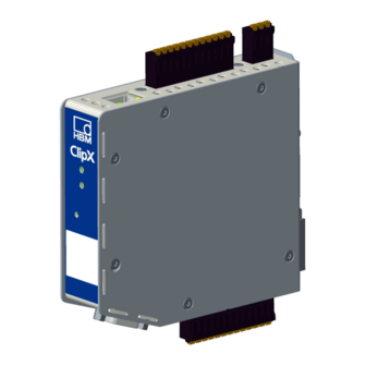
ClipX device types, scope of supply ClipX device types, scope of supply The ClipX is mounted directly on a support rail, though other mounting methods are also possible. The ClipX is supplied as standard with easy-fit push-in type plug terminals. You can also use screw-type plug terminals from Phoenix Con- tact –... -
Page 16: Scope Of Supply
ClipX device types, scope of supply Fig. 1: The ClipX device types from left to right: BM40, BM40PB and BM40IE To aid the design process, pre-compiled ePLAN macros (license- free) and 3D-STEP files are available free of charge at https://www.hbm.com/ClipX. - Page 17 ClipX with mounted support rail holder. • Bag containing three plug terminals, ordering number 1-CON-S1019 for sensor connection (13-pin), supply, digital I/O and ClipX bus (12-pin) as well as the analog output (3-pin). You can also order this plug terminal set sepa- rately.
-
Page 18: Dimensions
132.6 118.6 Fig. 2: ClipX dimensions when mounted on support rail (DIN rail 35mm to DIN EN 60715) with 16mm depth, all measures in mm To aid the design process, pre-compiled ePLAN macros (license- free) and 3D-STEP files are available free of charge at https://www.hbm.com/ClipX. -
Page 19: Mounting
Mounting on a support rail 1. Hang the ClipX from the top edge of the support rail. 2. Push the ClipX onto the support rail in the direction of the arrow as shown in the picture. The clip at the bottom secures the ClipX by a spring. -
Page 20: Dismounting From A Support Rail
1. Push the ClipX up. The spring mechanism allows you to release it from the top locator on the support rail. 2. Tilt the ClipX forward, rotating it as you do so. 3. Detach the ClipX downwards. ClipX a4643-1.0 HBM: public... -
Page 21: Other Mounting Options
Mounting Other mounting options Instead of using a support rail, you can mount the ClipX on a wall, for example, using an appropriate bracket. To do so, make a mounting bracket to fit on the back of the ClipX. Important: The vents on the back must not be covered over. The min- imum clearance between the back of the device and a wall in the area of the vents is 8mm. - Page 22 4. Fix your mount either using the original screws or using M3 screws pene- trating a maximum of 5mm into the housing. Fasten the screws only hand- tight. Important: You must ground the ClipX housing, such as by way of the mount. ClipX...
-
Page 23: Electrical Connections, Leds
The ClipX features IP20 protection in accordance with EN 60529 (protection against touch by fingers; protection against foreign bodies of Ø > 12mm). The ClipX is supplied as standard with easy-fit push-in terminals. But you can also obtain screw-type terminals from Phoenix Contact (https://www.phoenixcontact.com) (BK = black variant), e.g.:... - Page 24 • DI, GND (Ground) Digital-In: Reference potential for DI1 and DI2. • X, GND ClipX bus: Reference potential for ClipX bus (CxA, CxB) and Sync; on the BM40PB PROFIBUS-GND is also connected by this. • AI, GND Analog-In: Reference potential for U-In and I-In; the adjacent mea- surement inputs for voltage and current.
-
Page 25: Shielding And Grounding Design
(HBM recommendation: “Greenline shielding design” – see http://www.hbm.com/Greenline). Always connect the cable shield by the shortest possible length to the plug terminals and, as far as possible, lay the shield flat at the control cabinet inlet with shield connection terminal blocks, e.g. -
Page 26: Available Connections And Leds
Grounding Important: You must ground the support rail on which you mount the ClipX. If you want to mount the ClipX in a different way, such as on a wall, you must ground the housing by way of the mount. - Page 27 • DI, GND (Ground) Digital-In: Reference potential for DI1 and DI2. • X, GND ClipX bus: Reference potential for ClipX bus (CxA, CxB) and Sync; on the BM40PB PROFIBUS-GND is also connected by this. • AI, GND Analog-In: Reference potential for U-In and I-In; the adjacent mea- surement inputs for voltage and current.
-
Page 28: Health Monitoring, Leds
The BM40 only has the system LED. The following tables list the states indicated by the LEDs. The LEDs flash about once a second in flash mode, and about five times a second in rapid-flash mode. ClipX a4643-1.0 HBM: public... - Page 29 Electrical connections, LEDs System LED (SYS) Status Meaning No supply voltage, or ClipX defective. The ClipX has fully booted up, and is ready. Green Flashing Manual device detection (via the browser) has been started. Yellow Error on ClipX bus: – One or more of the expected devices is not transmitting, or not responding –...
-
Page 30: Led Status
Electrical connections, LEDs Status Meaning The ClipX is booting up (initializing everything) The parameter set is being changed One or more of the following measured values is invalid: – Raw value of A/D converter – Filtered value of A/D converter –... - Page 31 (2.5Hz) Possible cause: A change specified by the master is not possible. Single flash Local error: The ClipX has autonomously changed the EtherCAT status. Possible causes: – A host watchdog timeout has occurred, – synchronization error. In this case the device switches automatically to the SAFE-OPERATIONAL state.
- Page 32 Watchdog timeout. There is a system error, or a channel, generic or extended diagnosis. Status Meaning (bus error LED) No error. Flashing No data exchange. (2Hz) Error: No configuration, slow physical connection or no con- nection. ClipX a4643-1.0 HBM: public...
- Page 33 The ClipX is not on, or has no IP address. Flashing No network connection. But the ClipX has been assigned an IP address. (1Hz) Green The ClipX is connected to a network device, e.g. a switch. Flashing The ClipX is running a self-test. (1Hz) Red/ green ClipX a4643-1.0 HBM: public...
- Page 34 Meaning Flashing Connection timeout. (1Hz) One or more connections to this ClipX are in timeout. This status will only be terminated when all connections have been restored or you reset the ClipX. Duplicate IP address. The ClipX has detected that the IP address assigned to it (and set) is already being used in the network.
-
Page 35: Connecting The Supply Voltage
Supply 10 … 30 V Fig. 10: Supply voltage at plug terminal X2 For each ClipX you must provide a power output of 5W plus the power required for analog and digital outputs. Use an appropriately dimensioned cable for the supply voltage, so as to avoid an excessive voltage drop when operating mul- tiple devices. -
Page 36: Connecting Transducers
LEDs) and cable shielding (Shielding and grounding design). The signals of the connected sensor or signal are digitized by the ClipX at 19.2kHz. You can view various signal processing data values in your browser: • the field value, i.e. the input signal, •... - Page 37 Sense lead + Bridge excitation voltage + Outer cable shield Cable wire colors (HBM transducer): bu = blue; gn = green; gr = gray; rd = red; bk = black; wh = white; Fig. 11: Plug terminal X4, 6-wire pin assignment, TEDS optional ClipX a4643-1.0 HBM: public...
- Page 38 Sense lead + Bridge excitation voltage + Outer cable shield Cable wire colors (HBM transducer): bu = blue; gn = green; gr = gray; rd = red; bk = black; wh = white; Fig. 12: Plug terminal X4, 6-wire pin assignment, TEDS optional ClipX a4643-1.0 HBM: public...
- Page 39 Sense lead + Bridge excitation voltage + Outer cable shield Cable wire colors (HBM transducer): bu = blue; gn = green; gr = gray; rd = red; bk = black; wh = white; Fig. 13: Plug terminal X4, 6-wire pin assignment, TEDS optional ClipX a4643-1.0 HBM: public...
- Page 40 Bridge excitation voltage - Fühlerleitung + Bridge excitation voltage + Outer cable shield Cable wire colors (HBM transducer): bu = blue; gn = green; gr = gray; bk = black; wh = white; Fig. 14: Plug terminal X4, 6-wire pin assignment, TEDS optional ClipX a4643-1.0 HBM: public...
- Page 41 Bridge excitation voltage + Cable shield Feedback bridges for 4-wire circuitry Cable wire colors (HBM transducer): bu = blue; gn = green; gr = gray; rd = red; bk = black; wh = white; Fig. 15: Plug terminal X4, 4-wire pin assignment; pin 4 is not used for half bridge...
-
Page 42: Explosive Atmospheres
It is not possible to use transducers with TEDS when using Zener bar- riers. Use cable KAB 7.5/00-2/2/2 and safety barriers 1-SD01A from HBM to connect transducers in areas with potentially explosive atmospheres to the ClipX. The connection resistance of the sensor (or of multiple parallel configured sensors) must be between 80 and 350Ohms. -
Page 43: Potentiometric Transducer
(2 at 2' and 3 at 3') if you are not using a 6-wire configuration (with 5 wires assigned). Otherwise a sensor er- ror will be signaled, and you will not be able to measure (invalid mea- sured value). ClipX a4643-1.0 HBM: public... -
Page 44: Temperature Measurement By Pt100
The use of TEDS is not yet supported by the current firmware version. It will be in one of the future versions however. With the ClipX, temperatures can be measured in degrees Celsius, Kelvin or Fahrenheit using a Pt100 resistor. The cable resistance is adjusted by way of the sense line. -
Page 45: Voltage Source (±10V)
Measurement signal + Sense lead - Bridge excitation voltage - Sense lead + Bridge excitation voltage + Cable shield Analog GND Current input Voltage input Fig. 19: Plug terminal X4, pin assignment for electrical voltage source ClipX a4643-1.0 HBM: public... -
Page 46: Current Source (±20Ma Or 4 ... 20Ma)
Measurement signal - Measurement signal + Sense lead - Bridge excitation voltage - Sense lead + Bridge excitation voltage + Cable shield Analog GND Current input Voltage input Fig. 20: Plug terminal X4, pin assignment for current source ClipX a4643-1.0 HBM: public... -
Page 47: Current Drain (4 ... 20Ma)
Measurement signal + Sense lead - Bridge excitation voltage - Sense lead + Bridge excitation voltage + Cable shield Analog GND Current input Voltage input Fig. 21: Plug terminals X2 and X4, pin assignment for current drain ClipX a4643-1.0 HBM: public... -
Page 48: Connecting The Digital Inputs And Outputs
See also Available connections and LEDs. Digital inputs Housing, cable shield optional ClipX bus ClipX bus GND ClipX bus Sync Synchronization Digital In GND LOW: 0 V … 5 V Digital In 2 HIGH: 10 V … 30 V... -
Page 49: Digital Outputs
Fig. 23: Plug terminal X2, pin assignment of digital outputs Start-up behavior of the digital outputs On starting up the ClipX (power on), each output initially has a high output resis- tance. After initializing, the status of the settings is determined in the Start parameter set. -
Page 50: Connecting The Analog Output
Fig. 24: Plug terminal X2, pin assignment for analog output Start-up behavior On starting up the ClipX (power on), the analog output initially has a high output resistance. After initializing, the status of the settings is determined by the Boot parameter set. -
Page 51: Using Multiple Clipx Devices, Clipx Bus
You can transfer one measured value with status from each of up to six other ClipX devices over the ClipX bus to a ClipX and then capture them simultane- ously with the values of that device. The connections use line topology. The maximum cable length between two devices is 30cm. - Page 52 1000 values per second are transmitted per device (including CRC check). If you set Own Address for a device to 0, the ClipX bus will be deac- tivated for that device, meaning no other devices are visible, and no own signal can be transmitted.
-
Page 53: Synchronizing Multiple Clipx Cf Amplifiers
Lay the lines from the first device to the second, from the second to the third device, etc. (line topology). The cable must have twisted-pair wires, and be shielded. The ClipX bus GND and Sync lines must be twisted and shielded. - Page 54 Sensor Type menu items. Synchronization is only possi- ble for sensor types with carrier frequency (CF), not for DC. No synchronization of the time base or the A/D converters takes place. Housing, cable shields ClipX bus ClipX bus GND ClipX bus Sync Sync Synchronization...
-
Page 55: Signal Propagation Times Within The Clipx And Over The Clipx Bus
6.11 Signal propagation times within the ClipX and over the ClipX bus The various modules in the ClipX are combined into a number of groups, each with fixed cycle times. This makes it easier to calculate the total propagation time of a signal. The following diagrams indicate the propagation times of the various groups as well as any potential additions you might need to allow for the hardware of inputs/outputs. - Page 56 The digital outputs have an additional response time of max. 0.25 ms. Asynchronous transfer of the values on the ClipX bus is complete after max. 1 ms, i.e on the next cycle.
- Page 57 2 and can be outputted directly at the digital output for example. So the total propagation time is 940 … 1992µs. Example 3 Propagation time of a value from the ClipX bus via a limit value switch to a dig- ital output. •...
- Page 58 Electrical connections, LEDs Group 4: Data from ClipX to fieldbus master 1 ms approx. 250 μs 0.25 … 1 ms 250 μs Update rate EtherCAT/ PROFINET Period duration ClipX of frame rate fieldbus controller of fieldbus Update rate EtherNet/IP/ PROFIBUS At 4 kHz frame rate.
-
Page 59: Starting Up The Clipx
Power-up and operating behavior When the ClipX is powered up, all the inputs and output remain at 0 or 0.0V as appropriate. The start parameter set is loaded and activated first (= initializa- tion). -
Page 60: Connecting Via Ethernet
You have two options for connecting to the ClipX: 1. Make a direct 1:1 connection. Connect your PC and the ClipX by an Ethernet cable. In rare cases, you will need an Ethernet cross cable for this. Normally the PC will adapt automati- cally to the cable. - Page 61 Important: Do not use https; only http. If you have already changed the device name, you must enter the new name in place of ClipX. If you have forgotten the name, try one of the alternative options. Click on in the header and the SYS LED on the ClipX you are using will flash red/green.
-
Page 62: No Device Found
The apps use different connection methods – see also No device found? Under Linux you can also type one of the following lines to call up a list of ClipX devices and their IP addresses or MAC addresses respectively and enter them... - Page 63 For communication with the device via a browser, TCP ports 80 and 8081 are required. • Different ports are required to locate the ClipX depending on the variant. For UPnP TCP 80 and UDP-Multicast at IP address 239.255.255.250 (sending and receiving) with port 1900, for NetBIOS UDP 137, for Avahi or Zeroconf (similar to Bonjour) UDP-Multicast is required at IP address 224.0.0.251 (sending and receiving) with port 5353.
-
Page 64: Possible Cases And Their Effects When Connected Via Ethernet
When using Windows XP or higher, temporary addresses are automatically assigned by the PC (APIPA), the ClipX connection can be made. 2. No server in network, PC has no setting or is using DHCP, the ClipX has a fixed address No connection can be established with this combination. -
Page 65: Set Ethernet Address Of Pc
4. Select Internet protocol version 4 (TCP/IPv4) and click on Properties. 5. Activate Use the following IP address and enter an address with which the first three groups of numbers match the groups of numbers of the HBM device and only the last group of numbers contains a different number between 1 and 254. - Page 66 4. Select Internet protocol version 4 (TCP/IPv4) and click on Properties. 5. Activate Use the following IP address and enter an address with which the first three groups of numbers match the groups of numbers of the HBM device and only the last group of numbers contains a different number between 1 and 254.
- Page 67 5. Then click OK to close all open dialogs. You may have to restart the PC to activate the setting. Example The IP address of the ClipX is 192.168.169.80, the subnet mask is 255.255.255.0. Enter 192.168.169.123 as the IP address and 255.255.255.0 as the subnet mask on the PC.
-
Page 68: Resetting Ethernet Network Settings
3. Wait for the system LED to start flashing green before releasing the button. The ClipX will perform a restart automatically. 4. Wait until after the restart is finished before connecting to the device. -
Page 69: Setting The Clipx Using A Web Browser
The Ethernet API (Application Programming Interface) is a programming inter- face by which you can send data via the Ethernet port to the ClipX. The data are then displayed in the browser, and can be polled over the fieldbuses. You can program an Ethernet API yourself for example. - Page 70 You can save, load and activate parameter sets via the web browser or the fieldbus interface, or activate them only via the digital inputs. Processing parameter sets On a new ClipX all the parameter sets contain the factory setting. You can reset to those defaults at any time by clicking on FACTORY SETTINGS in the browser while a parameter set is active.
-
Page 71: Operation Via Fieldbus
You will find the device description files for cyclic data traffic between the PLC and ClipX on the HBM website: https://www.hbm.com/ClipX. Connecting the fieldbus The ClipX operates on all fieldbuses as a slave; it cannot be operated as a master. See also Available connections and LEDs. - Page 72 Important: The connections are not equivalent. Pay attention to the specified direction IN/OUT. Pin assignment for BM40IE, EtherNet/IP™ Port 1 EtherNet/IP™ master or EtherNet/IP™ slaves or switch Port 2 Fig. 36: X6, X7: Pin assignment for EtherNet/IP™ ClipX a4643-1.0 HBM: public...
-
Page 73: Data Types Used By The Clipx
Data types used by the ClipX. The following table sets out the data and the speed at which the data are down- loaded by the ClipX in the event of a change. The speed (cycle in ms) is not syn- ClipX a4643-1.0 HBM: public... - Page 74 Operation via fieldbus chronized with the fieldbus, or with PROFINET IRT or EtherCAT Distributed Clocks. The inputs and outputs of the ClipX are processed out of sync with the fieldbus. The synchronous modes of the ClipX with these fieldbus systems pro- vide only synchronized data transfer, not processing of the data.
- Page 75 Parameter set number. number Switches the ClipX to the parameter set with this number. The ClipX only reacts to a change in this value. The start value is 0. If you want to switch to parameter set 0 after the bus starts up, you must first change the value to unequal to 0.
- Page 76 The control word comprises 32 bits; the bits not listed here are reserved for later upgrades. The control word is acknowledged by ClipX – see Data transfer from the ClipX to the controller.
- Page 77 Reset limit value switch 3 Reset limit value switch 4 Reset maximum, minimum and peak-to-peak value Hold maximum, minimum and peak-to-peak value (as long as this bit is set) Filter fast-track. The filter output jumps to the input value. ClipX a4643-1.0 HBM: public...
-
Page 78: Data Transfer From The Clipx To The Controller
The following table sets out the data and the speed at which the data are updated by the ClipX in the event of a change. The speed (cycle in ms) is not synchronized with the fieldbus, or with PROFINET IRT or EtherCAT Distributed Clocks. - Page 79 Control word The echo of the control word – see section headed Data transfer to the ClipX. The UDINT desired function has been triggered when the received control word is equal to the one sent. Parameter Event- The number of the active parameter set.
-
Page 80: Settings For The Fieldbuses
The following sections set out the minimum settings you need to make in your web browser for the respective fieldbuses. See also Connecting via Ethernet, Setting the ClipX using a web browser. 8.5.1 Settings for PROFINET In your browser, specify the device name (Name of station). The name must be unique within the network. -
Page 81: Settings For Ethercat
Settings for EtherCAT You can specify all the settings via your EtherCAT configuration tool. To configure the ClipX, the EtherCAT master can either use the ESI file or – without an ESI file – download the object dictionary via the EtherCAT connection (device scan). -
Page 82: Settings For Profibus
FIBUS controller does not take this value from the GSD file, you must set it manually. The DPV1 objects are addressed by way of Slot and Index. Whether a module has been configured in a ClipX PROFIBUS slot (and if so, which one) is irrele- ClipX a4643-1.0 HBM: public... - Page 83 CiA404-compliant objects are located in slot 4. DPV1 objects R/W: RO = read only, RW = read and write, WO = write only. UINT = unsigned integer. The ClipX object directory index and subindex is stated for information purposes only. ClipX object DPV1...
- Page 84 Operation via fieldbus ClipX object DPV1 directory No of Data Description bytes type Sub- Slot Index Index index FLOAT External ClipX 2 0x44f0 value FLOAT External ClipX 3 0x44f0 value FLOAT External ClipX 4 0x44f0 value FLOAT External ClipX 5 0x44f0 value...
- Page 85 Operation via fieldbus ClipX object DPV1 directory No of Data Description bytes type Sub- Slot Index Index index FLOAT Analog output elec- 0x44f0 trical value UINT32 All measval statuses 0x44f4 FLOAT Discharge rate Min / 0x4021 second FLOAT Discharge rate Max /...
- Page 86 Operation via fieldbus ClipX object DPV1 directory No of Data Description bytes type Sub- Slot Index Index index UINT8 Hold Min/Max flags 0x4027 invert Clear Min/Max com- 0x4028 mand UINT8 Hold Min/Max 0x4029 0:normal evaluation 1:hold active UINT8 Captured value 1...
- Page 87 Operation via fieldbus ClipX object DPV1 directory No of Data Description bytes type Sub- Slot Index Index index UINT8 Captured value 1 0x4035 invert trigger UINT8 Captured value 2 0x4035 invert trigger UINT32 Captured value 1 0x4036 clear mask low...
- Page 88 Operation via fieldbus ClipX object DPV1 directory No of Data Description bytes type Sub- Slot Index Index index Command 0x403b TRIGGER captured value 2 UINT8 All statuses limit 0x4600 switches UINT8 Limit switch 1 status 0x4601 UINT8 Limit switch 2 status...
- Page 89 Operation via fieldbus ClipX object DPV1 directory No of Data Description bytes type Sub- Slot Index Index index FLOAT Limit switch 0x4604 threshold 3 FLOAT Limit switch 0x4604 threshold 4 FLOAT Limit switch 0x4605 hysteresis 1 FLOAT Limit switch 0x4605...
- Page 90 Operation via fieldbus ClipX object DPV1 directory No of Data Description bytes type Sub- Slot Index Index index UINT32 Limit switch reset 0x4608 mask low 4 UINT32 Limit switch reset 0x4609 mask high 1 UINT32 Limit switch reset 0x4609 mask high 2...
- Page 91 Operation via fieldbus ClipX object DPV1 directory No of Data Description bytes type Sub- Slot Index Index index FLOAT Analog output scal- 0x4500 ing electr. value 2 FLOAT Analog output scal- 0x4500 ing electr. offset FLOAT Analog output electr. 0x4500...
- Page 92 0 … 6 UINT8 ClipX bus, highest 0x4380 address 0 … 6 UINT8 ClipX bus, value 0x4380 index to send 0 … UINT16 ClipX bus, cycles per 0x4380 second UINT16 ClipX bus, restart 0x4380 counter UINT8 TEDS, select zero / 0x4300...
- Page 93 Operation via fieldbus ClipX object DPV1 directory No of Data Description bytes type Sub- Slot Index Index index UINT8 TEDS usage 0x4300 0: ignore 1: if available 2: force UINT8 TEDS search during 0x4300 paraset change 0: no 1: yes UINT16 Get active param.
- Page 94 Operation via fieldbus ClipX object DPV1 directory No of Data Description bytes type Sub- Slot Index Index index STRING Name of param. set 0x4271 STRING Name of param. set 0x4271 UINT32 All system status bits 0x4200 STRING Name of param. set...
- Page 95 Operation via fieldbus ClipX object DPV1 directory No of Data Description bytes type Sub- Slot Index Index index UINT32 CRC of a param. set 0x4272 0 in RAM cache UINT32 CRC of a param. set 0x4272 1 in RAM cache UINT32 CRC of a param.
- Page 96 Operation via fieldbus ClipX object DPV1 directory No of Data Description bytes type Sub- Slot Index Index index FLOAT Field value 0x6100 UINT8 Scale 1 FV count 0x6120 FLOAT Scale 1 FV 0x6120 UINT8 Scale 1 PV count 0x6121 FLOAT...
- Page 97 Operation via fieldbus ClipX object DPV1 directory No of Data Description bytes type Sub- Slot Index Index index UINT8 Status count 0x6150 UINT8 Status 0x6150 UINT8 Filter type count 0x61a0 UINT8 Filter type 0x61a0 UINT8 Filter frequency 0x61a2 count FLOAT...
- Page 98 Operation via fieldbus ClipX object DPV1 directory No of Data Description bytes type Sub- Slot Index Index index STRING Protocol date 0x4800 STRING FW revision 0x4900 UINT32 Revision counter 0x4900 UINT32 HW revision 0x4900 STRING IM function tag 0x4900 STRING...
-
Page 99: Flags And Status Bits
Operation via fieldbus ClipX object DPV1 directory No of Data Description bytes type Sub- Slot Index Index index FLOAT User signal 4 0x5003 FLOAT User signal 5 0x5003 FLOAT User signal 6 0x5003 FLOAT User signal 7 0x5003 FLOAT User signal 8... - Page 100 Captured value 1. Captured value 2 Captured value 2. ClipX bus value 1 Value on the device's ClipX bus with address 1. ClipX bus value 2 Value on the device's ClipX bus with address 2. ClipX bus value 3 Value on the device's ClipX bus with address 3.
-
Page 101: System Status: List Of Status Bits
The following table sets out the bits in the system status (32bits) if the status in question is set. Status/error Explanation for bit set Device ready The ClipX is switched on, initialized, and the Ethernet connection is live. Sync master The device is configured as the master for CF synchro- nization. - Page 102 The ClipX bus is not working correctly. Check the wir- ing of the bus system. Error external RAM Error in the RAM of the ClipX (not in the RAM of the CPU). Make a note of the error type and contact Tech- nical support at HBM.
-
Page 103: Flags: List Of Possible I/O Flags (I/O Status)
Flags 1 to 8 of the calculated channels. 20 … 29 Not in use. Always 0. Always 1. 32 … 47 Flags 1 to 16 of the fieldbus. I/O status high 48 … 63 Flags 1 to 16 of the Ethernet API. ClipX a4643-1.0 HBM: public... -
Page 104: The Control Word
The control word comprises 32 bits; the bits not listed here are reserved for later upgrades. The control word is acknowledged by ClipX – see Data transfer from the ClipX to the controller. -
Page 105: Calibration Certificates
Calibration certificates Calibration certificates In production of the ClipX, HBM draws up a declaration of compliance with the order 2.1 in accordance with EN 10204 or a manufacturer's certificate O in accordance with DIN 55350 part 18. The working standard calibration certificate for your ClipX is available to down- load from the HBM website at https://www.hbm.com/en/6871/support-download-... - Page 106 Calibration certificates ClipX a4643-1.0 HBM: public...
-
Page 107: Diagnostics And Error Rectification, Faqs
Diagnostics and error rectification, FAQs Diagnostics and error rectification, FAQs 10.1 Possible errors For the ClipX to be ready, the LEDs must light in the relevant colors – see Health monitoring, LEDs. You can identify by this whether the device has (has been assigned) an IP address, whether the device itself was initialized without error, or whether the fieldbus of the BM40IE or BM40PB is working correctly. - Page 108 Measuring range of full -2.5 mV/V bridge CF 2.5mV/V Measuring range of full mV/V bridge CF 5mV/V Measuring range of potentiometer Measuring range of 18.52 390.48 ohms Pt100 Analog output 10V Analog output 4 ... 20mA ClipX a4643-1.0 HBM: public...
-
Page 109: Faqs
– see Connecting via Ethernet. Can I reset the Ethernet network settings (IP address) to their factory defaults? Yes. Use the push button on the front of the ClipX to do so – see Resetting Ethernet network settings. ClipX... - Page 110 You can interconnect up to six devices over the ClipX bus. Each device can transmit a signal on the bus, so up to five signals from other ClipX devices are available on each device. The measured values are transferred automatically.
- Page 111 Yes. The value transmitted over the ClipX bus of a ClipX can be processed, i.e in calculations or functions such as peak value, captured values, etc. Note that the values from the ClipX bus might have a delay of up to 1ms relative to your own values.
- Page 112 You can download the current version of the firmware from https://www.hbm.com/ClipX. Where can I find the current device description files? You can download the current files for your fieldbus (if available) from the ClipX using your web browser – see Connecting via...
-
Page 113: Technical Support
Technical support Technical support If problems occur when working with the ClipX, you can use the following ser- vices: E-mail support info@hbm.com Telephone support Telephone support is available on all working days from 09:00 to 5:00 PM (CET): +49 6151 803-0... - Page 114 Technical support Asia Hottinger Baldwin Measurement (Suzhou) Co., Ltd. 106 Heng Shan Road, Suzhou 215009, Jiangsu, China Tel. +86 512-68247776, Fax +86 512-68259343 E-mail: hbmchina@hbm.com.cn ClipX a4643-1.0 HBM: public...
-
Page 115: Maintenance
Maintenance Maintenance The ClipX system is maintenance-free. Important: You must not open the device. Cleaning • Before cleaning, cut all connections, i.e disconnect the (push-in or screw- type) plug terminals. • Clean the housing with a soft, slightly damp (not wet!) cloth. You should never use solvents, since these could damage the labeling. - Page 116 Maintenance ClipX a4643-1.0 HBM: public...
-
Page 117: Disposal
European waste electrical and electronic equipment directive 2002/96/EC. The symbol indicates that the device must not be disposed of as household gar- bage. As waste disposal regulations differ from country to country, please contact your local authority or HBM representative as necessary. ClipX a4643-1.0 HBM: public... - Page 118 Disposal ClipX a4643-1.0 HBM: public...
-
Page 119: Index
6-wire configuration with Zener barrier single-shielded 23 Connecting transducers 34 Connecting via Ethernet 58 About ClipX 11 Connections 24 Accuracy of the ClipX 109 Electrical isolation 22 Analog output 48 Connector options 107 Areas with potentially explosive atmo- Control word 74... - Page 120 61 Mounting Firmware on a support rail 17 Download current 110 Other options 19 Grounding 24 No device found? 60 Grounding design 23 Operating behavior 57 HBM Sales worldwide 111 Operating software 108 HBM Support 111 ClipX a4643-1.0 HBM: public...
- Page 121 Safety instructions 5 Sampling rates 109 Using multiple ClipX devices 49 Scope of supply 14 Using parameter sets 67 scope of supply 13 Setting the ClipX using a web browser Voltage source 43 Setup software 108 ClipX a4643-1.0 HBM: public...
- Page 122 Index Web browser Setting the ClipX 67 Windows 10 Changing the IP address of the PC Windows 7 Changing the IP address of the PC Windows 8 Changing the IP address of the PC Windows XP Change IP address of PC 64...
- Page 123 Operating Manual | Bedienungsanleitung English Deutsch ClipX...
- Page 124 Überblick ..........11 ClipX-Gerätetypen, Lieferumfang ......13 Gerätetypen .
- Page 125 Inhaltsverzeichnis ClipX in Betrieb nehmen ....... . . 57 Einschalt- und Betriebsverhalten ......57 Über Ethernet verbinden.
- Page 126 Inhaltsverzeichnis ClipX a4643-1.0 HBM: public...
- Page 127 Beachten Sie die in den technischen Daten angegebenen maximal zuläs- sigen Umgebungstemperaturen. • Die zulässige relative Luftfeuchte bei 31°C beträgt 95% (nicht kondensie- rend); lineare Reduzierung bis 50% bei 40°C. • Das ClipX kann bis zu einer Höhe von 2000m sicher betrieben werden. ClipX a4643-1.0 HBM: public...
- Page 128 Normen der Sicherheitstechnik in Betrieb zu nehmen, zu erden und zu kennzeichnen. Restgefahren Das ClipX-System entspricht dem Stand der Technik und ist betriebssicher. Der Leistungs- und Lieferumfang des ClipX-Systems deckt allerdings nur einen Teil- bereich der Messtechnik ab. Sicherheitstechnische Belange der Messtechnik sind zusätzlich vom Anlagenplaner/Ausrüster/Betreiber so zu planen, zu reali-...
- Page 129 Zuständen oder Datenverlust in der Automatisierungseinrichtung führen. In dieser Anleitung verwendeter Sicherheitshinweis HINWEIS Dieses Symbol weist auf eine Situation hin, die – wenn die Sicherheitsbestim- mungen nicht beachtet werden – Sachschäden zur Folge haben kann. ClipX a4643-1.0 HBM: public...
- Page 130 Sicherheitshinweise ClipX a4643-1.0 HBM: public...
- Page 131 Kennzeichnung für die Zulassung zum Verkauf des Gerätes in die russi- sche Förderation. CE-Kennzeichnung Mit der CE-Kennzeichnung garantiert der Hersteller, dass sein Produkt den Anforderungen der relevanten EG-Richtlinien entspricht. Die Konfor- mitätserklärung finden Sie auf der Website von HBM https://www.hbm.com unter HBMdoc. Angaben in dieser Anleitung nachlesen und berücksichtigen. ClipX...
- Page 132 Symbole auf dem Gerät ClipX a4643-1.0 HBM: public...
- Page 133 Acrobat Reader bei Bedarf (kostenlos) auf der Website von Adobe. ClipX-Steckbrief Mit dem Kauf eines ClipX-Messverstärkers haben Sie sich für ein kompaktes, leistungsstarkes und variables Messsystem in hoher HBM-Qualität entschieden. Sie können das ClipX über die Standard-Ethernet-Schnittstelle an einen PC anschließen und über den geräteinternen Webserver parametrieren und...
- Page 134 Siehe auch Sicherheitshinweise. Wichtig: Dieses Symbol weist auf ein wichtiges Detail oder eine Be- sonderheit hin. Absätze mit diesem Symbol geben einen Tipp oder erläutern ein inter- essantes Feature. Absätze mit diesem Symbol enthalten zusätzliche Informationen. ClipX a4643-1.0 HBM: public...
- Page 135 ClipX-Gerätetypen, Lieferumfang ClipX-Gerätetypen, Lieferumfang Das ClipX wird direkt auf eine Tragschiene montiert, andere Montagearten sind jedoch ebenfalls möglich. Das ClipX wird serienmäßig mit montagefreundlichen Steckklemmen in Push-In-Technologie geliefert. Sie können auch Steck- klemmen in Schraubtechnik von Phoenix Contact verwenden, siehe Elektrische Anschlüsse,...
- Page 136 ClipX-Gerätetypen, Lieferumfang Abb. 1: Die ClipX-Gerätetypen von links nach rechts: BM40, BM40PB und BM40IE Zur Unterstützung der Konstruktion stehen Ihnen fertige ePLAN- Makros (lizenzfrei) und 3D-STEP-Dateien auf https://www.hbm.com/ClipX kostenlos zur Verfügung. EtherNet/IP™ is a trademark of ODVA Inc. For more information regarding ODVA, visit www.odva.org.
- Page 137 Lieferumfang • ClipX mit montierter Tragschienenhalterung. • Beutel mit 3 Steckklemmen, Bestellnr. 1-CON-S1019 für Sensoranschluss (13-polig), Versorgung, Digital I/O und ClipX-Bus (12-polig) sowie den Ana- logausgang (3-polig). Diesen Steckklemmensatz können Sie auch separat bestellen. • Eine Kurzanleitung mit Sicherheitshinweisen (a4838).
- Page 138 Abmessungen 127,7 111,7 132,6 118,6 Abb. 2: ClipX-Abmessungen bei Montage auf Tragschiene (DIN-Schiene 35mm entsprechend DIN EN 60715) mit 16mm Tiefe, alle Maße in mm Zur Unterstützung der Konstruktion stehen Ihnen fertige ePLAN- Makros (lizenzfrei) und 3D-STEP-Dateien auf https://www.hbm.com/ClipX kostenlos zur Verfügung.
- Page 139 Abb. 3: Montage auf einer Tragschiene 1. Hängen Sie das ClipX auf der oberen Kante der Tragschiene ein. 2. Drücken Sie das ClipX wie im Bild mit dem Pfeil angezeigt auf die Trag- schiene auf. Der untere Haken sichert über eine Feder den festen Sitz des ClipX.
- Page 140 1. Drücken Sie das ClipX nach oben. Der Federmechanismus ermöglicht Ihnen das Ausrasten aus der oberen Führung der Tragschiene. 2. Kippen Sie das ClipX mit einer drehenden Bewegung nach vorne. 3. Ziehen Sie das ClipX nach unten ab. ClipX a4643-1.0 HBM: public...
- Page 141 Montage Andere Montagemöglichkeiten Anstatt eine Tragschiene zu verwenden, können Sie das ClipX auch über einen geeigneten Winkel z.B. an eine Wand montieren. Konstruieren Sie dazu einen Befestigungswinkel, der sich an die Rückseite des ClipX anschrauben lässt und den Sie dann zur weiteren Befestigung verwenden.
- Page 142 4. Schrauben Sie Ihre Befestigung entweder mit den Originalschrauben auf oder verwenden Sie M3-Schrauben, die maximal 5mm in das Gehäuse ein- dringen. Ziehen Sie die Schrauben nur handfest an. Wichtig: Sie müssen das Gehäuse des ClipX erden, z.B. über die Be- festigung. ClipX...
- Page 143 Elektrische Anschlüsse, LEDs Elektrische Anschlüsse, LEDs Das ClipX ist in Schutzart IP20 nach EN 60529 ausgeführt (Schutz gegen Berührung mit den Fingern, Schutz gegen Fremdkörper mit Ø > 12mm). Das ClipX wird serienmäßig mit montagefreundlichen Steckklemmen in Push- In-Technologie geliefert. Sie können jedoch die passende Ausführung mit Steck- klemmen in Schraubtechnik bei Phoenix Contact erhalten (https://www.phoenixcontact.com) (BK = schwarze Ausführung), z.B.:...
- Page 144 Elektrische Anschlüsse, LEDs Funktionsweise (Blockschaltbild) Die folgende Abbildung zeigt Ihnen die Funktionsweise und das Zusammen- spiel der verschiedenen Ein- und Ausgänge des ClipX. Die galvanische Tren- nung der verschiedenen Funktionsblöcke ist ebenfalls eingezeichnet: Zwischen der Spannungsversorgung und allen Signaleingängen und -Ausgängen besteht eine galvanische Trennung.
- Page 145 Abb. 7: Schirmklemme für flaches Auflegen von Kabelschirmen (Beispiel) Doppelt geschirmte Anschlussleitungen, z.B. für Sensorkabel Wir empfehlen, soweit möglich das Kabel Kab 7.5/00-2/2/2 von HBM zu ver- wenden. Das Kabel ist doppelt geschirmt und kapazitätsarm. Verbinden Sie bei doppelt geschirmten Kabeln den äußeren Schirm nur mit den Anschluss für das Gehäuse (Erde-Symbol...
- Page 146 ). Bei Schaltschränken legen Sie diesen Schirm auch am Schaltschrank auf, siehe Abbildung Schirmklemme. Erdung Wichtig: Sie müssen die Tragschiene erden, auf der Sie das ClipX montieren. Falls Sie das ClipX anders befestigen möchten, z.B. an einer Wand, müssen Sie das Gehäuse über die Befestigung erden.
- Page 147 Die folgenden Anschlüsse sind jeweils voneinander galvanisch getrennt: • DI, GND (Ground) Digital-In: Bezugspotenzial für DI1 und DI2. • X, GND ClipX-Bus: Bezugspotenzial für ClipX-Bus (CxA, CxB) und Sync, beim BM40PB ist auch PROFIBUS-GND hiermit verbunden. • AI, GND Analog-In: Bezugspotenzial für U-In und I-In, die benachbarten Messeingänge für Spannung und Strom.
- Page 148 Bei BM40 ist nur die System-LED vorhanden. Die folgenden Tabellen zeigen Ihnen die Zustände, die durch die LEDs signali- siert werden. Die LEDs blinken ca. 1 Mal pro Sekunde im Zustand blinkend und ca. 5 Mal pro Sekunde im Zustand schnell blinkend. ClipX a4643-1.0 HBM: public...
- Page 149 Elektrische Anschlüsse, LEDs System-LED (SYS) Zustand Bedeutung Versorgungsspannung fehlt oder ClipX defekt. Das ClipX hat vollständig gebootet und ist bereit. grün Blinkend Die manuelle Geräteerkennung (über den Browser) wurde gestartet. gelb Fehler auf dem ClipX-Bus: – eines oder mehrere der erwarteten Geräte sendet nicht bzw.
- Page 150 Das ClipX befindet sich im Zustand INIT. Blinkend Das ClipX befindet sich im Zustand PRE-OPERATIONAL 2,5Hz (vor dem Betrieb). Einfach auf- Das ClipX befindet sich im Zustand SAFE-OPERATIONAL blitzend (im sicheren Betriebsmodus). grün Das ClipX befindet sich im Zustand OPERATIONAL (im Betrieb). ClipX a4643-1.0 HBM: public...
- Page 151 Ungültige Konfiguration. (2,5Hz) Mögliche Ursache: Eine durch den Master vorgegebene Änderung ist nicht möglich. Einfach auf- Lokaler Fehler: Das ClipX hat den EtherCAT-Status eigen- blitzend ständig geändert. Mögliche Ursachen: – Ein Timeout des Host-Watchdogs ist aufgetreten, – Synchronisationsfehler. Das Gerät wechselt in diesem Fall automatisch in den Zustand SAFE-OPERATIONAL.
- Page 152 Es gibt einen Systemfehler oder es liegt eine Channel-, eine generische oder eine erweiterte Diagnose vor. Zustand Bedeutung (Bus-Fehler-LED Es liegt kein Fehler vor. Blinkend Es findet kein Datenaustausch statt. (2Hz) Fehler: Keine Konfiguration, langsame oder keine physikali- sche Verbindung vorhanden. ClipX a4643-1.0 HBM: public...
- Page 153 Schwerer Fehler: Es gibt einen nicht behebbaren Fehler. Bitte kontaktieren Sie die Technische Unterstützung HBM. Zustand Bedeutung Das ClipX ist nicht eingeschaltet oder hat keine IP-Adresse. Blinkend Keine Netzwerkverbindung vorhanden. Das ClipX hat (1Hz) jedoch eine IP-Adresse erhalten. grün Das ClipX ist mit einem Netzwerkgerät verbunden, z.B.
- Page 154 Das ClipX hat festgestellt, dass die ihm zugewiesene (gesetzte) IP-Adresse im Netzwerk bereits verwendet wird. PROFIBUS-LED (BUS, nur BM40PB) Zustand Bedeutung Das ClipX ist nicht eingeschaltet oder das Netzwerk hat keine Spannung. Zyklisch blin- Der Master ist im Zustand CLEAR. kend (2Hz) grün...
- Page 155 Versorgung 10 … 30 V Abb. 10: Versorgungsspannung an Steckklemme X2 Pro ClipX müssen Sie eine Leistung von 5W zuzüglich der für analoge und digi- tale Ausgänge benötigten Leistung vorsehen. Verwenden Sie ein entsprechend dimensioniertes Kabel für die Versorgungsspannung, um bei mehreren Geräten ClipX a4643-1.0 HBM: public...
- Page 156 (Vorhandene Anschlüsse und LEDs) und der Schirmung von Kabeln (Schirmungs- und Erdungskonzept). Die Signale des angeschlossenen Sensors bzw. Signals werden vom ClipX mit 19,2kHz digitalisiert. Sie können sich im Browser verschiedene Werte der Sig- nalverarbeitung anzeigen lassen: • Den Feldwert, d.h. das Eingangssignal, •...
- Page 157 Fühlerleitung + Brückenspeisespannung + Äußerer Kabelschirm Kabeladerfarben (HBM-Aufnehmer): bl = blau; gn = grün; gr = grau; rt = rot; sw = schwarz; ws = weiß; Abb. 11: Steckklemme X4, Anschlussbelegung in 6-Leiter-Schaltung, TEDS op- tional ClipX a4643-1.0 HBM: public...
- Page 158 Fühlerleitung + Brückenspeisespannung + Äußerer Kabelschirm Kabeladerfarben (HBM-Aufnehmer): bl = blau; gn = grün; gr = grau; rt = rot; sw = schwarz; ws = weiß; Abb. 12: Steckklemme X4, Anschlussbelegung in 6-Leiter-Schaltung, TEDS op- tional ClipX a4643-1.0 HBM: public...
- Page 159 Fühlerleitung + Brückenspeisespannung + Äußerer Kabelschirm Kabeladerfarben (HBM-Aufnehmer): bl = blau; gn = grün; gr = grau; rt = rot; sw = schwarz; ws = weiß; Abb. 13: Steckklemme X4, Anschlussbelegung in 6-Leiter-Schaltung, TEDS op- tional ClipX a4643-1.0 HBM: public...
- Page 160 TEDS Brückenspeisespannung - Fühlerleitung + Brückenspeisespannung + Äußerer Kabelschirm Kabeladerfarben (HBM-Aufnehmer): bl = blau; gn = grün; gr = grau; sw = schwarz; ws = weiß; Abb. 14: Steckklemme X4, Anschlussbelegung in 6-Leiter-Schaltung, TEDS op- tional ClipX a4643-1.0 HBM: public...
- Page 161 Rückführbrücken für 4-Leiter-Technik Kabeladerfarben (HBM-Aufnehmer): bl = blau; gn = grün; gr = grau; rt = rot; sw = schwarz; ws = weiß; Abb. 15: Steckklemme X4, Anschlussbelegung in 4-Leiter-Schaltung; bei Halb- brücke entfällt Anschluss 4, TEDS optional ClipX a4643-1.0 HBM: public...
- Page 162 Zenerbarrieren nicht möglich. Verwenden Sie das Kabel KAB7.5/00-2/2/2 und die Sicherheitsbarrieren 1- SD01A von HBM, um Aufnehmer, die sich in einem explosionsgefährdetem Bereich befinden, an das ClipX anzuschließen. Der Anschlusswiderstand des Sensors (oder mehrerer parallel geschalteter) muss zwischen 80 und 350Ohm liegen.
- Page 163 Wichtig: Verbinden Sie die Fühlerleitungen mit den entsprechenden Speisespannungsleitungen durch Drahtbrücken (2 mit 2' und 3 mit 3'), falls Sie keine 6-Leiter-Schaltung (mit 5 belegten Adern) verwen- den. Andernfalls wird ein Sensorfehler gemeldet und Sie können nicht messen (ungültiger Messwert). ClipX a4643-1.0 HBM: public...
- Page 164 Die Verwendung von TEDS wird von der aktuellen Firmware noch nicht unterstützt. Dies wird jedoch in einer der nächsten Versionen der Fall sein. Mit dem ClipX lassen sich Temperaturen in Grad Celsius, Kelvin oder Fahren- heit mit einem Pt100-Widerstand messen. Der Kabelwiderstand wird über die Fühlerleitung ausgeregelt.
- Page 165 Fall sein. Siehe auch Vorhandene Anschlüsse und LEDs. Pt100 Pt100 TEDS 1-Wire-TEDS Messsignal - Messsignal + Fühlerleitung - Brückenspeisespannung - Fühlerleitung + Brückenspeisespannung + Kabelschirm Analog GND Stromeingang Spannungseingang Abb. 19: Steckklemme X4, Anschlussbelegung elektrische Spannungsquelle ClipX a4643-1.0 HBM: public...
- Page 166 Dies wird jedoch in einer der nächsten Versionen der Fall sein. Siehe auch Vorhandene Anschlüsse und LEDs. Pt100 TEDS 1-Wire-TEDS Messsignal - Messsignal + Fühlerleitung - Brückenspeisespannung - Fühlerleitung + Brückenspeisespannung + Kabelschirm Analog GND Stromeingang Spannungseingang Abb. 20: Steckklemme X4, Anschlussbelegung Stromquelle ClipX a4643-1.0 HBM: public...
- Page 167 Versorgung 0 V Versorgung 10 … 30 V Pt100 TEDS 1-Wire-TEDS Messsignal - Sensor Messsignal + Fühlerleitung - Brückenspeisespannung - Fühlerleitung + Brückenspeisespannung + Kabelschirm Analog GND Stromeingang Spannungseingang Abb. 21: Steckklemmen X2 und X4, Anschlussbelegung Stromsenke ClipX a4643-1.0 HBM: public...
- Page 168 Änderung nach spätestens 1ms ausgewertet. Siehe auch Vorhandene Anschlüsse und LEDs. Digitale Eingänge Gehäuse, Kabelschirm optional ClipX-Bus ClipX-Bus GND ClipX-Bus Sync Synchronisation Digital-In GND LOW: 0 V … 5 V Digital-In 2 HIGH: 10 V … 30 V Digital-In 1...
- Page 169 Versorgung 10 … 30 V Abb. 23: Steckklemme X2, Anschlussbelegung Digitalausgänge Einschaltverhalten der digitalen Ausgänge Beim Einschalten (Spannungsversorgung ein) des ClipX hat jeder Ausgang zunächst einen hohen Ausgangswiderstand. Nach der Initialisierung wird der Zustand von den Einstellungen im Start-Parametersatz bestimmt. Bei aktivem Ausgang wird die Versorgungsspannung (10 …...
- Page 170 Wert im Fehlerfall Welcher Wert ausgegeben wird, hängt davon ab, ob Sie den Wert bei „ungültig“- Signal aktivieren oder nicht. Nehmen Sie die Einstellung über den ClipX-Web- server und Ihren Browser vor. 1. Wert bei „ungültig“-Signal aktiv (Schalter im Browser rechts und rot) Falls das Eingangssignal ungültig wird oder das Ausgangssignal die Werte...
- Page 171 Elektrische Anschlüsse, LEDs Mehrere ClipX verwenden, ClipX-Bus Sie können über den ClipX-Bus je einen Messwert mit Status von bis zu 6 anderen ClipX auf ein Gerät übertragen und dann gleichzeitig mit den Werten dieses Gerätes erhalten. Die Verbindungen verwenden Linien-Topologie, die maximale Kabellänge zwischen zwei Geräten ist 30cm.
- Page 172 Elektrische Anschlüsse, LEDs Stelle das eigene Gerät erscheinen soll) über Ihren Browser eingeben (Menü ClipX-Bus) Das Gerät mit der Adresse 1 arbeitet als Bus-Master, alle anderen als Bus-Slaves. Legen Sie bei den einzelnen Geräten fest, welches Signal gesendet werden soll. Zusätzlich zum Messsignal wir auch der Status (gültig/ungültig) übertragen.
- Page 173 Synchronisation nötig. Verbinden Sie für die Synchronisation jeweils die Sync-Anschlüsse der Geräte und die ClipX-Bus GND-Anschlüsse, falls Sie diese nicht bereits für die Übertra- gung von Messwerten verbunden haben. Legen Sie die Leitungen vom ersten zum zweiten Gerät, von diesem zum dritten Gerät usw. (Linien-Topologie). Das Kabel muss verdrillte Adern besitzen und geschirmt sein.Die Leitungen ClipX-...
- Page 174 Verstärker und Sensortyp vor. Die Synchronisation ist nur bei Sen- sortypen mit TF (Trägerfrequenz) möglich, nicht bei DC. Eine Syn- chronisation der Zeitbasis oder der A/D-Wandler findet nicht statt. Gehäuse, Kabelschirm ClipX-Bus ClipX-Bus GND ClipX-Bus Sync Sync Synchronisation Digital-In GND...
- Page 175 Abb. 29: Minimale Laufzeit für Gruppe 1: 52µs plus A/D-Wandler-Konvertierzeit Einige Signale können auch Quellen aus anderen Gruppen haben. Zum Bei- spiel könnte der Analogausgang ein Signal vom ClipX-Bus ausgeben. Für die Gesamtlaufzeit müssen Sie in diesen Fällen die Laufzeit der Gruppe des Quell- signals addieren.
- Page 176 Spitzenwerte zurücksetzen, gehaltene Werte halten, gehaltene Werte löschen. Bei den digitalen Ausgängen kommt noch eine Reaktionszeit von max. 0,25 ms hinzu. Die asynchrone Übertragung der Werte auf dem ClipX-Bus ist spätestens nach 1 ms beendet, d. h., zum nächsten Zyklus.
- Page 177 Digitaler Ausgang: 1ms plus max. 250µs Reaktionszeit Damit ergibt sich eine Gesamtlaufzeit von 2,3ms. Allerdings müssen Sie die Laufzeit in dem Gerät, das den Wert auf den ClipX-Bus legt, hinzurechnen, um die Zeit vom Sensor bis zur Reaktion zu erhalten.
- Page 178 Elektrische Anschlüsse, LEDs Gruppe 4: Daten vom ClipX zum Feldbus-Master 1 ms ca. 250 μs 0,25 … 1 ms 250 μs Updaterate EtherCAT/ PROFINET Periodendauer ClipX- der Framerate Feldbus- Controller des Feldbusses Updaterate EtherNet/IP/ PROFIBUS Bei 4 kHz Framerate. Abb. 32: Laufzeit für Gruppe 4 ClipX a4643-1.0 HBM: public...
- Page 179 Der erste Abschnitt dieses Kapitels erläutert das generelle Einschalt- und Betriebsverhalten des ClipX nach einer erfolgreichen Installation. Danach sind die Schritte erläutert, die Sie benötigen, um das ClipX in Betrieb zu nehmen. Für die erste Inbetriebnahme sollten Sie das ClipX über Ethernet an einen PC anschließen.
- Page 180 ClipX in Betrieb nehmen Bis zu drei Clients (PCs) können sich mit einem ClipX verbinden, jede weitere Verbindung wird dann abgelehnt. Wichtig: Manche Browser bauen mehr als eine Verbindung auf. In diesem Fall reduziert sich die Anzahl der möglichen weiteren Verbin- dungen.
- Page 181 ClipX in Betrieb nehmen Adressen gelingt dies nur, wenn PC und ClipX Adressen aus dem gleichen Netzwerksegment verwenden (Werkseinstellung ClipX: DHCP). Die Verbin- dungen verwenden IPv4, IPv6 wird nicht unterstützt. Verwenden Sie die erste Variante, falls Sie mehrere ClipX verwenden möchten.
- Page 182 ClipX in Betrieb nehmen 1. Öffnen Sie den Windows-Explorer. 2. Klicken Sie auf Netzwerk. 3. Im Bereich Andere Geräte sollte nach einigen Minuten das ClipX-Gerät (mit dem Namen des Gerätes, Werkseinstellung ClipX) erscheinen. 4. Doppelklicken Sie auf das Symbol. Falls Sie die IP-Adresse des Gerätes kennen, können Sie auch diese in der Adresszeile des Browsers eingeben, z.B.
- Page 183 ClipX in Betrieb nehmen Allgemeine Gründe • Ist das Gerät wirklich an (Stromversorgung)? • Leuchtet die System-LED des ClipX grün? Siehe auch Health-Monitoring, LEDs. • Ist das Schnittstellenkabel angeschlossen? • Leuchtet mindestens eine der LEDs in der Netzwerkbuchse? • Haben Sie die richtige Schnittstelle bzw. den richtigen Schnittstellenadapter...
- Page 184 • Unter WindowsXP steht nur die Namensauflösung unter NetBIOS zur Verfü- gung. • Bei der Namensauflösung über NetBIOS sollten Sie immer nur ein ClipX anschließen, solange Sie die Gerätenamen nicht geändert haben. • UPnP steht erst ab Windows7 zur Verfügung.
- Page 185 ClipX hat eine feste Adresse Mit dieser Kombination kann keine Verbindung hergestellt werden. 3. Kein Server im Netzwerk, PC und ClipX haben eine feste Adresse Eine Verbindung kann i.d.Regel nur hergestellt werden, wenn die Adressen von PC und ClipX im gleichen Netzwerksegment liegen und wenn beide die gleiche Subnetzmaske verwenden.
- Page 186 5. Aktivieren Sie Folgende IP-Adresse verwenden und geben Sie eine Adresse ein, bei der die ersten drei Zifferngruppen mit den Zifferngruppen des HBM-Gerätes übereinstimmen und nur die letzte Zifferngruppe eine andere Zahl zwischen 1 und 254 enthält. Die letzte Zifferngruppe darf nicht mit der Zifferngruppe am HBM-Gerät übereinstimmen!
- Page 187 5. Aktivieren Sie Folgende IP-Adresse verwenden und geben Sie eine Adresse ein, bei der die ersten drei Zifferngruppen mit den Zifferngruppen des HBM-Gerätes übereinstimmen und nur die letzte Zifferngruppe eine andere Zahl zwischen 1 und 254 enthält. Die letzte Zifferngruppe darf nicht mit der Zifferngruppe am HBM-Gerät übereinstimmen!
- Page 188 5. Schließen Sie dann alle offenen Dialoge durch Klick auf OK. Evtl. müssen Sie den PC neu starten, um die Einstellung zu aktivieren. Beispiel Die IP-Adresse des ClipX beträgt 192.168.169.80, die Subnetzmaske beträgt 255.255.255.0. Geben Sie 192.168.169.123 als IP-Adresse und 255.255.255.0 als Subnetz- maske am PC ein.
- Page 189 3. Warten Sie, bis die System-LED grün flackert und lassen Sie erst dann den Taster wieder los. Das ClipX führt selbstständig einen Neustart durch. 4. Warten Sie bis nach dem Neustart, bevor Sie sich mit dem Gerät verbinden.
- Page 190 Klicken Sie auf , um die SYS-LED des verwendeten ClipX rot/grün blinken zu lassen, falls Sie mehrere ClipX angeschlossen haben. Speichern Sie nach dem Einstellen über Ihren Browser die gesamten Geräteeinstellungen des ClipX mit dem Menü Gerätespeicher auf Ihren...
- Page 191 Einstellungen, Filter oder der Analogausgang geändert werden, für ca. 2,5 Sekunden der Messwertstatus auf UNGÜLTIG gesetzt, um Einschwingvor- gänge auf den Ausgängen ausblenden zu können.Auf dem ClipX-Bus kann es dabei auch zu kurzen Timeouts kommen (SYS-LED wird gelb). ClipX a4643-1.0 HBM: public...
- Page 192 ClipX in Betrieb nehmen ClipX a4643-1.0 HBM: public...
- Page 193 BM40PB relevant. Die Geräteausführung BM40 verfügt über keinen Feldbus. Die Gerätebeschreibungsdateien für den zyklischen Datenverkehr zwischen SPS und ClipX finden Sie auf der HBM-Website: https://www.hbm.com/ClipX. Feldbus anschließen Das ClipX arbeitet in allen Feldbussen als Slave-Gerät, ein Betrieb als Master ist nicht möglich. Siehe auch Vorhandene Anschlüsse und LEDs.
- Page 194 Abb. 35: X6, X7: Anschlussbelegung EtherCAT Wichtig: Die Anschlüsse sind nicht gleichwertig, beachten Sie die an- gegebene Richtung IN/OUT. Anschlussbelegung BM40IE, EtherNet/IP™ Port 1 EtherNet/IP™-Master oder EtherNet/IP™-Slaves oder Switch Port 2 Abb. 36: X6, X7: Anschlussbelegung EtherNet/IP™ ClipX a4643-1.0 HBM: public...
- Page 195 Anschlussbelegung BM40IE, PROFINET Port 1 PROFINET-Master oder PROFINET-Slaves oder Switch Port 2 Abb. 37: X6, X7: Anschlussbelegung PROFINET Vom ClipX verwendete Datentypen Die folgende Tabelle enthält die in den Befehlsbeschreibungen verwendeten Abkürzungen für die Datentypen. Abkürzung Beschreibung REAL, FLOAT 32 Bit, Fließkommazahl...
- Page 196 PROFINET IRT oder EtherCAT Distributed Clocks. Die Ein- und Aus- gänge des ClipX werden asynchron zum Feldbus verarbeitet. Die synchronen Modi des ClipX bei diesen Feldbus-Systemen stellen nur die synchrone Daten- übertragung sicher, nicht die Verarbeitung. Die Verarbeitungszeit von Anfragen und Befehlen, z.B.
- Page 197 Format Funktion in ms Fieldbus flags UINT 16 Steuerflags, die im ClipX wie interne Flags universell benutzt werden können, z.B. zum Zurücksetzen von Spitzenwerten. Diese Flags werden in den digitalen Flags in die Bits 32 … 47 übertragen. Siehe auch Abschnitte Flags: Liste der möglichen I/O-Flags...
- Page 198 (Index) nis nach Index und Subindex, das Padding- request USINT Byte hat keine Funktion. (Sub- Das ClipX reagiert nur auf Änderungen von index) Index, Subindex, Padding-Byte oder Wert. USINT Es reagiert nicht, wenn Index = 0x0000 ist (Padding) (no operation).
- Page 199 Betrieb über Feldbus löst. Das Steuerwort besteht aus 32 Bits, die hier nicht aufgeführten Bits sind für spätere Erweiterungen reserviert. Das Steuerwort wird von ClipX quittiert, siehe Datenübertragung vom ClipX zur Steuerung. Wenn die Quittung gleich dem gesendeten Steuerwort ist, wurde die Aktion ausgeführt und Sie können das Bit löschen.
- Page 200 Datentypen. Die folgende Tabelle enthält die Daten und die Geschwindigkeit, mit der die jeweiligen Daten vom ClipX bei einer Änderung aktualisiert werden. Diese Geschwindigkeit (Zyklus in ms) ist nicht mit dem Feldbus synchronisiert, auch nicht bei PROFINET IRT oder EtherCAT Distributed Clocks.
- Page 201 Statusbits. 0,052 … value status UDINT (Mess- wertstatus) Steuerwort Das Echo des Steuerworts, siehe Abschnitt Datenübertragung zum ClipX. Die UDINT gewünschte Funktion wurde ausgelöst, wenn das empfangene Steuerwort gleich dem gesendeten ist. Parameter Ereignis- Die Nummer des aktiven Parametersatzes. UINT...
- Page 202 Die folgende Tabelle zeigt die Byte-Zuordnung des Objekt-Wertes bei Zugriffen auf das Objektverzeichnis. Bit 31 … 24 Bit 23 … 16 Bit 15 … 8 Bit 7 … 0 Datenobjekt-Typen UDINT, DINT, REAL nicht benutzt Datenobjekt-Typen INT, UINT nicht benutzt Datenobjekt-Typen SINT, USINT ClipX a4643-1.0 HBM: public...
- Page 203 (PDO Assignment) selbst vornehmen. Aktivieren Sie danach im Master den Download, damit die Zuordnung zum ClipX übertragen wird. SAFE-OPERATIONAL Das ClipX besitzt keinen sicheren Zustand der Ausgänge. Beim Übergang von OPERATIONAL nach SAFE-OPERATIONAL behalten die von EtherCAT gesteuerten Ausgänge ihren momentanen Wert und werden in SAFE-OPERA- TIONAL nicht mehr aktualisiert.
- Page 204 Gerät zu übertragen. 8.5.4 Einstellungen für PROFIBUS Legen Sie im Browser die Adresse des ClipX auf dem PROFIBUS fest. Die Werkseinstellung ist 126 (ungültige Adresse). Die Bitrate wird vom ClipX auto- matisch erkannt. Nehmen Sie die weitere Konfiguration des Feldbusses über Ihr PROFIBUS-Konfigurationstool vor.
- Page 205 CiA404-konforme Objekte befinden sich in Slot 4. DPV1-Objekte R/W (Zugriffsart): RO = read only, RW = read and write, WO = write only. UINT = unsigned integer. Index und Subindex des ClipX object directory sind nur zur Information ange- geben. ClipX object DPV1...
- Page 206 FLOAT Max value 0x44f0 FLOAT Peak-to-peak value 0x44f0 FLOAT Captured value 1 0x44f0 FLOAT Captured value 2 0x44f0 FLOAT External ClipX 1 0x44f0 value FLOAT External ClipX 2 0x44f0 value FLOAT External ClipX 3 0x44f0 value FLOAT External ClipX 4...
- Page 207 Betrieb über Feldbus ClipX object DPV1 directory No of Data Description bytes type Sub- Slot Index Index index FLOAT Calculated channel 3 0x44f0 value FLOAT Calculated channel 4 0x44f0 value FLOAT Calculated channel 5 0x44f0 value FLOAT Calculated channel 6...
- Page 208 Betrieb über Feldbus ClipX object DPV1 directory No of Data Description bytes type Sub- Slot Index Index index UINT32 Discharge Max divi- 0x4021 UINT8 Signal source 0x4020 Min/Max UINT32 Clear Min/Max flags 0x4022 mask low UINT32 Clear Min/Max flags 0x4023...
- Page 209 Betrieb über Feldbus ClipX object DPV1 directory No of Data Description bytes type Sub- Slot Index Index index UINT8 Captured value 1 0x4032 status 0:valid 1: invalid UINT8 Captured value 2 0x4032 status 0:valid 1: invalid UINT32 Captured value 1...
- Page 210 Betrieb über Feldbus ClipX object DPV1 directory No of Data Description bytes type Sub- Slot Index Index index UINT8 Captured value 1 0x4038 invert clear UINT8 Captured value 2 0x4038 invert clear UINT8 Captured value 1 0x4039 valuesource UINT8 Captured value 2...
- Page 211 Betrieb über Feldbus ClipX object DPV1 directory No of Data Description bytes type Sub- Slot Index Index index UINT8 Limit switch Reset 0x4603 command single 1 (1: reset) UINT8 Limit switch Reset 0x4603 command single 2 (1: reset) UINT8 Limit switch Reset...
- Page 212 Betrieb über Feldbus ClipX object DPV1 directory No of Data Description bytes type Sub- Slot Index Index index UINT8 Limit switch source 1 0x4606 UINT8 Limit switch source 2 0x4606 UINT8 Limit switch source 3 0x4606 UINT8 Limit switch source 4...
- Page 213 Betrieb über Feldbus ClipX object DPV1 directory No of Data Description bytes type Sub- Slot Index Index index UINT8 Limit switch reset 0x460a invert 2 UINT8 Limit switch reset 0x460a invert 3 UINT8 Limit switch reset 0x460a invert 4 UINT8...
- Page 214 0 … 6 UINT8 ClipX bus, highest 0x4380 address 0 … 6 UINT8 ClipX bus, value 0x4380 index to send 0 … UINT16 ClipX bus, cycles per 0x4380 second UINT16 ClipX bus, restart 0x4380 counter ClipX a4643-1.0 HBM: public...
- Page 215 Betrieb über Feldbus ClipX object DPV1 directory No of Data Description bytes type Sub- Slot Index Index index UINT8 TEDS, select zero / 0x4300 1-wire-connection TEDS, read serial 0x4300 command from HW (TID) STRING TEDS, read serial 0x4300 from buffer (TID)
- Page 216 Betrieb über Feldbus ClipX object DPV1 directory No of Data Description bytes type Sub- Slot Index Index index UINT8 Digital IN switch 0x4270 mode 0: off 1: digital IN 0 2: digital IN 0+1 Command: Activate 0x4270 factory default UINT32...
- Page 217 Betrieb über Feldbus ClipX object DPV1 directory No of Data Description bytes type Sub- Slot Index Index index STRING Name of param. set 0x4271 STRING Name of param. set 0x4271 STRING Name of param. set 0x4271 STRING Name of param. set...
- Page 218 Betrieb über Feldbus ClipX object DPV1 directory No of Data Description bytes type Sub- Slot Index Index index UINT32 CRC of a param. set 0x4272 8 in RAM cache UINT32 CRC of a param. set 0x4272 9 in RAM cache...
- Page 219 Betrieb über Feldbus ClipX object DPV1 directory No of Data Description bytes type Sub- Slot Index Index index UINT8 Process value count 0x6130 FLOAT Process value 0x6130 UINT8 Tare offset count 0x6138 FLOAT Tare offset 0x6138 UINT8 Autotare count 0x6139...
- Page 220 Betrieb über Feldbus ClipX object DPV1 directory No of Data Description bytes type Sub- Slot Index Index index UINT8 AO scale 1 FV count 0x6321 FLOAT AO scale 1 FV 0x6321 UINT8 AO scale 2 PV count 0x6322 FLOAT AO scale 2 PV...
- Page 221 Betrieb über Feldbus ClipX object DPV1 directory No of Data Description bytes type Sub- Slot Index Index index UINT16 Function block 1 0x5001 UINT16 Function block 2 0x5001 UINT16 Function block 3 0x5001 UINT16 Function block 4 0x5001 UINT16 Function block 5...
- Page 222 Gehaltener Wert 1. Captured value 2 Gehaltener Wert 2. ClipX bus value 1 Wert auf dem ClipX-Bus vom Gerät mit der Adresse 1. ClipX bus value 2 Wert auf dem ClipX-Bus vom Gerät mit der Adresse 2. ClipX bus value 3 Wert auf dem ClipX-Bus vom Gerät mit der Adresse 3.
- Page 223 Betrieb über Feldbus Bezeichnung Erläuterung ClipX bus value 6 Wert auf dem ClipX-Bus vom Gerät mit der Adresse 6. Calculated value 1 Wert des Berechnungskanals 1. Calculated value 2 Wert des Berechnungskanals 2. Calculated value 3 Wert des Berechnungskanals 3.
- Page 224 Fehler ClipX-Bus Der ClipX-Bus arbeitet nicht richtig. Überprüfen Sie die Verschaltung des Bussystems. Fehler externes Fehler im RAM des ClipX (nicht im RAM der CPU). Notieren Sie die Fehlerart und kontaktieren Sie die Technische Unterstützung von HBM. Fehler Sensor- Die Speisespannung für den Sensor ist kurzgeschlos-...
- Page 225 BM40PB). Notieren Sie die Fehlerart und kontak- tieren Sie die Technische Unterstützung von HBM. Fehler Kalibrierung Die Kalibrierung des ClipX ist fehlerhaft. Notieren Sie die Fehlerart und kontaktieren Sie die Technische Unterstützung von HBM. Reserviert Nicht belegt und reserviert für zukünftige Erweiterun- …...
- Page 226 12 … 19 Flags 1 bis 8 der Berechnungskanäle. 20 … 29 Nicht belegt. Immer 0. Immer 1. 32 … 47 Flags 1 bis 16 des Feldbusses. I/O-Status high 48 … 63 Flags 1 bis 16 der Ethernet-API. ClipX a4643-1.0 HBM: public...
- Page 227 Tarieren bei jeder Änderung eines der anderen Bits erneut ausge- löst. Das Steuerwort besteht aus 32 Bits, die hier nicht aufgeführten Bits sind für spätere Erweiterungen reserviert. Das Steuerwort wird von ClipX quittiert, siehe Datenübertragung vom ClipX zur Steuerung. Wenn die Quittung gleich dem gesendeten Steuerwort ist, wurde die Aktion ausgeführt und Sie können das Bit löschen.
- Page 228 Betrieb über Feldbus Funktion Maximum-, Minimum- und Spitze-Spitze-Wert halten (solange dieses Bit gesetzt ist) Filter-Fasttrack. Der Filterausgang springt auf den Eingangswert. ClipX a4643-1.0 HBM: public...
- Page 229 Kalibrierzertifikate Kalibrierzertifikate Bei der Fertigung des ClipX erstellt HBM eine Werksbescheinigung 2.1 nach EN 10204 bzw. ein Herstellerzertifikat O nach DIN 55350 Teil 18. Der Werkskalibrierschein Ihres ClipX steht Ihnen über die HBM-Webseite https://www.hbm.com/en/6871/support-download-calibration-certificates/ Verfügung. Der ClipX-Werkskalibrierschein beinhaltet folgende Kalibrierungen: •...
- Page 230 Kalibrierzertifikate ClipX a4643-1.0 HBM: public...
- Page 231 Diagnose und Fehlerbeseitigung, FAQ Diagnose und Fehlerbeseitigung, FAQ 10.1 Mögliche Fehler Damit das ClipX bereit ist, müssen die LEDs die entsprechenden Farben zeigen, siehe Health-Monitoring, LEDs. Sie können daran erkennen, ob das Gerät eine IP-Adresse (bekommen) hat, ob das Gerät selbst fehlerfrei initiali- siert wurde oder ob bei BM40IE oder BM40PB der Feldbus korrekt funktioniert.
- Page 232 DC 100mV/V Messbereich Voll- -800 -850 mV/V brücke DC 800mV/V Messbereich Voll- -2,5 mV/V brücke TF 2,5mV/V Messbereich Voll- mV/V brücke TF 5mV/V Messbereich Potenzio- meter Messbereich Pt100 18,52 390,48 Analogausgang 10V Analogausgang 4 … 20mA ClipX a4643-1.0 HBM: public...
- Page 233 Diagnose und Fehlerbeseitigung, FAQ 10.2 FAQ Gibt es beim ClipX Sicherungen die gewechselt werden müssen? Nein. Das ClipX verfügt über eine interne Strombegrenzung, die im Störfall die Leistungsaufnahme automatisch regelt. Gibt es bewegliche Teile, die gewartet werden müssten? Nein. Das ClipX kommt ohne Lüfter u.ä. aus und ist wartungsfrei.
- Page 234 ClipX-Bus. Wozu ist der ClipX-Bus gut? Sie können über den ClipX-Bus bis zu 6 Gerät miteinander verbinden. Jedes Geräte kann ein Signal auf diesem Bus übertragen, so dass an jedem Gerät bis zu 5 Signale anderer ClipX zur Verfügung stehen. Die Übertragung der Mess- werte erfolgt automatisch, Sie müssen nur an jedem Gerät festlegen, welches...
- Page 235 Ja. der über den ClipX-Bus übertragene Wert eines ClipX kann verarbeitet werden, d.h. in Berechnungen oder Funktionen wie Spitzenwert, gehaltene Werte etc. Beachten Sie, dass die Werte vom ClipX-Bus bis zu 1ms Verzöge- rung gegenüber den eigenen Werten haben können.
- Page 236 Verfügung. Woher bekomme ich Unterstützung bei Fragen? Bei technischen Fragen steht Ihnen der HBM-Support (TSC, Technisches Sup- port Center, support@hbm.com) zur Verfügung. Bei Fragen zur technischen Projektierung und Auslegung beantworten unsere Kollegen vom Application Engineering gerne Ihre Fragen oder kommen zu Ihnen vor Ort: applicationengineering@hbm.com.
- Page 237 Technische Unterstützung Technische Unterstützung Sollten bei der Arbeit mit dem ClipX Probleme auftreten, haben Sie die Möglich- keit, folgende Dienste zu nutzen: E-Mail-Unterstützung info@hbm.com Telefon-Unterstützung Die telefonische Unterstützung ist von 9:00 bis 17:00 Uhr (MEZ) an allen Werk- tagen verfügbar: +49 6151 803-0 Fax-Unterstützung...
- Page 238 Technische Unterstützung Asien Hottinger Baldwin Measurement (Suzhou) Co., Ltd. 106 Heng Shan Road, Suzhou 215009, Jiangsu, VR China Tel. +86 512-68247776, Fax +86 512-68259343 E-Mail: hbmchina@hbm.com.cn ClipX a4643-1.0 HBM: public...
- Page 239 Wartung Wartung Das ClipX-System ist wartungsfrei. Wichtig: Sie dürfen das Gerät nicht öffnen. Reinigung • Trennen Sie vor der Reinigung die Verbindung zu allen Anschlüssen, d.h., ziehen Sie die Steckklemmen (Push-In- oder Schraubklemmen) ab. • Reinigen Sie das Gehäuse mit einem weichen und leicht angefeuchteten (nicht nassen!) Tuch.
- Page 240 Wartung ClipX a4643-1.0 HBM: public...
- Page 241 Das Symbol weist darauf hin, dass das Gerät nicht im Hausmüll entsorgt werden darf. Da die genauen Entsorgungsvorschriften von Land zu Land unterschiedlich sind, bitten wir Sie, sich im Bedarfsfall an die örtlichen Behörden oder an die betreffende HBM-Vertretung zu wenden. ClipX a4643-1.0 HBM: public...
- Page 242 Entsorgung ClipX a4643-1.0 HBM: public...
- Page 243 Index Index Numerics 4-Leiter-Schaltung 39 ClipX in Betrieb nehmen 57 6-Leiter-Schaltung 35 ClipX mit Webbrowser einstellen 68 6-Leiter-Schaltung mit Zenerbarriere ClipX Sicherungen 111 ClipX synchronisieren 51 ClipX-Bus 51 Abmessungen 16 ClipX-Gerätetypen 13 Abtastraten 113 ClipX-Steckbrief 11 Analogausgang 48 Andere ClipX 49 Demontage 18 Anschlüsse 24...
- Page 244 Index Elektrische Anschlüsse 21 Genauigkeit des ClipX 113 E-Mail-Unterstützung 115 Gerätetypen 13 Entsorgung 119 Erdung 24 HBM-Support 115 Erdungskonzept 23 HBM-Vertrieb weltweit 115 Ethernet Health Monitoring 26 Verbindung herstellen 58 Ethernet-Adresse ändern IP-Adresse PC 63 Werkseinstellung 67 Ethernet-API 68 zurücksetzen 67 Ethernet-Schnittstelle IP-Adresse ändern...
- Page 245 Index Messprogramme Stromsenke 45 wie viele? 113 Symbole auf dem Gerät 9 Messwerte auf ein anderes ClipX über- Synchronisierung 51 tragen 49 Mögliche Fälle bei Ethernet-Verbindun- gen 63 Technische Unterstützung 115 Mögliche Fehler 109 Telefon-Unterstützung 115 Montage Temperaturmessung 42 Andere Möglichkeiten 19 TF-Verstärker synchronisieren 51...
- Page 246 Index Windows 8 IP-Adresse des PCs ändern 64 Windows XP IP-Adresse des PCs ändern 65 IP-Adresse des PCs ändern 65 ClipX a4643-1.0 HBM: public...
- Page 248 HBM Test and Measurement Tel. +49 6151 803-0 Fax +49 6151 803-9100 info@hbm.com measure and predict with confidence...
Need help?
Do you have a question about the ClipX and is the answer not in the manual?
Questions and answers