
Related Manuals for Grundfos DID Series


Summary of Contents for Grundfos DID Series
- Page 1 GRUNDFOS INSTRUCTIONS Installation and operating instructions Other languages http://net.grundfos.com/qr/i/99037650...
-
Page 2: Table Of Contents
English (GB) Installation and operating instructions 1. General information Original installation and operating instructions These installation and operating instructions describe Grundfos 1.1 Target group DID (Dosing Instrumentation Digital). Sections 1-6 give the information necessary to be able to unpack, 1.1.1 Qualification and training install and start up the product in a safe way. -
Page 3: Symbols On The Product
Grundfos Service Hotline. operator must make sure that no Scanning the QR code forwards counterpressure is on the outlet. you to the Grundfos support site. Before taking a sample for calibration, flush the sampling point 3-4 times with approximately 10 ml each time. -
Page 4: Installation
2. Connect the Rp 1/2" hose adaptor fittings to the inlet and the sensor. Find the manual "Sensors for DID" on outlet. Grundfos Product Center: (http://net.grundfos.com/ – The Rp 1/2" hose adaptor fittings are included in the Appl/ccmsservices/public/literature/filedata/ standard delivery of the DID. -
Page 5: Starting Up The Product
5. Starting up the product 5.1 Initial startup Description and use of the terminals WARNING Terminal Description Electric shock Phase - Switch off the power supply before startup. Power supply Neutral - IP65 only applies, if the housing cover and the (100-240 V, terminal compartment of the CU 382 are properly 50-60 Hz) -
Page 6: Connecting The Sensors To The Cu 382 Control Unit
6.2 Connecting the sensors to the CU 382 control unit 7. Storing and handling the product All sensors for the DID have plugs. • Before storing the DID, empty all pipes, hoses and flow cells, remove the sensors and pack them separately. Sensors for immersion have fixed cables with plugs. -
Page 7: Product Introduction
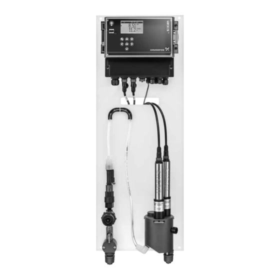
8. Product introduction 8.1 Product description Pos. Description Water inlet, G 1/2 internal thread, connections for Grundfos hoses Ball valve, 1/4 NPT Inlet strainer, with screw cap for removal and cleaning of the sieve Flow restrictor, mechanical Flow detector, digital... -
Page 8: Identification
8.4 Identification 8.4.2 Type key Example: DID-3 BF3-FCL2/TCL2/pH 8.4.1 Nameplate Code Description CU 382-1 for 1 parameter + DID-1 CU 382 temperature, 100-240 VAC, 50-60 Hz control unit CU 382-3 for 3 parameters + variant DID-3 temperature, 100-240 VAC, 50-60 Hz Bypass flow cell, 1 sensor 10,11,12 Bypass flow cell, 3 sensors... -
Page 9: Operation
9. Operation 9.1 Operating elements 9.2 Display screen Fig. 9 CU 382 display screen Pos. Description Top menu bar Fig. 8 CU 382 operating elements Symbols in the top menu bar of the display screen: [Right] symbol Pos. Description • If this symbol is shown, you can navigate to Power LED, green the next menu with the [Right] button. -
Page 10: Software Overview
9.3 Software overview The CU 382 has different screens and menus, which can be selected by the [Right] and [Left] buttons. The default screen is the parameter screen. When pressing the [Back] button several times in a submenu, you come back to one of the following screens: Service Status Parameter... - Page 11 9.3.1 Service screen 9.3.4 Controller screen The service menu is not required for the applications described in Up to 3 controllers can be configured and displayed. this manual. Scroll through the list of controllers with the [Up] and [Down] buttons. Service Timeout [min]: C2/2 pH...
-
Page 12: General Setup
9.3.5 Alarm screen 9.4 General setup In the "Setup" menu, general settings can be made. AP001 A1/1 • Press the [Function] button in the status screen to open the "Setup" menu. 2020/Sep/05 16:40:21 Setup pHbelow Manage sensors... ► lower alarm limit Cleaning 1... - Page 13 9.4.1 Manage sensors Adding a parameter Add para. Manage sensors Add pH ► ► pH::lyser Add pH-mV chlori::lyser Add Temp Digital Input 1 Add sensor... 1. Select a parameter with the [Up] and [Down] buttons. pH::lyser/0/1 2. Confirm with [OK]. Names of the connected sensors chlori::lyser/0/2 Removing a sensor...
- Page 14 9.4.4 Date/Time 9.4.2 Cleaning device The "Cleaning 1..." and "Cleaning 2..." menus are used for the Date/Time DID with sensor for tank immersion, if an automatic cleaning Year : ► 2020 device is installed. Month : Cleaning 1... Day : Interval [s]: ►...
- Page 15 9.4.5 MODBUS slave 9.4.8 Service If the CU 382 is used as a Modbus slave, the connection settings Setup can be configured in the "MODBUS slave" menu. Access code: ► 0001 MODBUS slave Address: ► Parity: Baudrate: 38400 Use the "Access code:" "0001" to open the "Service" menu. Service Address: The Modbus ID.
-
Page 16: Parameter Setup
9.5.1 Calibrate expert... 9.5 Parameter setup In the parameter setup menu, a parameter can be calibrated, monitored, linked to an alarm, linked to an output or removed. Before calibration make sure that the parameter value is stable. P1 FCL/mg/l Calibrate expert... ►... - Page 17 Performing "Offset" calibration "Span" calibration The "Offset" calibration is an in-situ calibration. The sensor must P1 Calibrate expert... not be removed from the flow cell. Type: Local 1. Select "Offset" in the "Mode:" entry field with the [Up] and ► [Down] buttons.
- Page 18 9.5.2 Monitor... Changing the unit of the parameter 1. Select "Unit:" with the [Up] and [Down] buttons. Confirm with The "Monitor..." menu shows the internal value, raw value and [OK]. status information of the chosen parameter and sensor. The operator can identify problems with the sensors in the "Monitor..." 2.
- Page 19 Defining the output of an alarm Digital outputs 1. Select "Output:" with the [Up] and [Down] buttons. Confirm The following output types can be defined: with [OK]. Level • 2. Select "none", "DigOut #1" or "DigOut #2" with the [Up] and PULSE •...
- Page 20 Enabling the pH compensation 1. Select "Type:" with the [Up] and [Down] buttons. Confirm with P2 Output settings... [OK]. Type: 2. Change the type to "Auto" with the [Up] and [Down] buttons. ► Confirm with [OK]. [0%] 0.00 – The pH compensation is enabled. [100%] 14.00 Defining the source for pH compensation...
-
Page 21: Controller Setup
9.6.1 Setpoint... 9.6 Controller setup The setpoint of the controller can be defined directly in the In the controller setup menu, a setpoint can be defined, controller operating software of the controller, or an external setpoint parameters can be configured, the input for the controller can be adjustment can be configured. - Page 22 9.6.2 Settings PID Changing the controller type 1. Select "Type:" with the [Up] and [Down] buttons. Confirm with C2 Settings [OK]. 2. Select "PID", "2-P" or "none" with the [Up] and [Down] Type: ► buttons. Confirm with [OK]. Kp [%] –...
- Page 23 Changing the direction of the controller Changing the hysteresis of the controller 1. Select "Direction:" with the [Up] and [Down] buttons. Confirm 1. Select "Hysteresis:" with the [Up] and [Down] buttons. Confirm with [OK]. with [OK]. 2. Select "up" or "down" with the [Up] and [Down] buttons. 2.
-
Page 24: Usb Menu / Data Transfer
Changing the digital output to "PWM" 9.7 USB menu / Data transfer 1. Select "Type:" with the [Up] and [Down] buttons. Confirm with The USB menu is activated when a USB stick is plugged in the [OK]. USB slot. 2. Select "PWM" with the [Up] and [Down] buttons. Confirm with USB data transfer [OK]. -
Page 25: Maintenance
10. Refit the hose. 11. Screw on the hose connection. 10.1.3 Sensor See the manual "Sensors" supplied with the sensor. Find the manual "Sensors for DID" on Grundfos Product Center: (http:// net.grundfos.com/Appl/ccmsservices/public/literature/filedata/ Grundfosliterature-6119622.pdf). 10.1.4 Control unit CU 382 If necessary, clean the surfaces of the CU 382 control unit with a... -
Page 26: Functional Check
(water quality), the sensors connected and the environmental conditions. For the functional check of the sensors, see the manual "Sensors" supplied with the sensor. Find the manual "Sensors for DID" on Grundfos Product Center: (http://net.grundfos.com/Appl/ ccmsservices/public/literature/filedata/Grundfosliterature- 6119622.pdf). Component Functional check... -
Page 27: Fault Finding
11. Fault finding See also the manual "Sensors" supplied with the sensor. Find the manual "Sensors for DID" on Grundfos Product Center: (http:// net.grundfos.com/Appl/ccmsservices/public/literature/filedata/Grundfosliterature-6119622.pdf). Fault Cause Remedy 1. No water flow a) The inlet valve is closed. Open the inlet valve completely. -
Page 28: Technical Data
12. Technical data 12.1 Hydraulic specifications of DID Variants BF1 and BF3 Data Unit 3 + 1 optical Number of connectable s::can sensors sensor Minimum liquid temperature* [°C] General data Maximum liquid temperature* [°C] Minimum ambient temperature* [°C] Maximum ambient temperature* [°C] Minimum flow rate [l/h]... - Page 29 4-20 mA analog input Description Unit D-320-GF1-230 (CU 382-1) D-320-GF3-230 (CU 382-3) Number of inputs Connection Terminal block, stripped wire, AWG 28-12 Input resistance [Ohm] Galvanic isolation [kV] 1 kV to system ground/earth Minimum input current [mA] Maximum input current [mA] Resolution of reading 12-bit...
- Page 30 Cleaning output Description Unit D-320-GF1-230 (CU 382-1) D-320-GF3-230 (CU 382-3) Number of outputs Connection Terminal block, stripped wire, AWG 28-12 For use with s::can cleaning valve B-44 or flow-cell autobrush F-446-2/F- Intended use 446-1 Sensor Description Unit D-320-GF1-230 (CU 382-1) D-320-GF3-230 (CU 382-3) 1 x Buccaneer 400 Series Connection...
-
Page 31: Weights
12.3 Weights Without With packaging packaging DID type [kg] [kg] DID-1 BF1 4.00 7.69 DID-1 BF1-FCL2 4.26 8.10 DID-1 BF1-FCL20 4.26 8.10 DID-1 BF1-CDI2 4.26 8.10 DID-1 BF1-PH 4.25 8.09 DID-1 BF1-CND 4.25 8.09 DID-1 TI1-PH 2.08 5.88 DID-1 TI1-CND 2.08 5.88 DID-3 BF3... -
Page 32: Disposal
This product or parts of it must be disposed of in an environmentally sound way: 1. Use the public or private waste collection service. 2. If this is not possible, contact the nearest Grundfos company or service workshop. The crossed-out wheelie bin symbol on a product means that it must be disposed of separately from household waste. - Page 33 The sensor manual contains general information, safety guidelines and technical data of the s::can sensors as well as instructions for installation, calibration, functional check, maintenance and troubleshooting. Find the manual "Sensors for DID" on Grundfos Product Center: http://net.grundfos.com/Appl/ccmsservices/public/literature/filedata/ Grundfosliterature-6119622.pdf Video instructions The following video instructions are available on YouTube: •...
- Page 34 Declaration of conformity GB: EC declaration of conformity We, s::can Messtechnik GmbH, hereby declare that the product listed below, to which this Declaration of Conformity relates, is in conformity with Directives, Standards and other Normative Documents as listed. Type of product: Measurement & Process Control Name of product: DID Model number: D-320-GF1-230, D-320-GF3-230 —...
- Page 35 Appendix YETKİLİ GRUNDFOS SERVİSLERİ Telefon İlgili Kişi Firma Adres Cep telefonu Eposta Faks GEBZE ORGANİZE SANAYİ BÖLGESİ. İHSAN 0262 679 79 79 GRUNDFOS POMPA EMRAH ŞİMŞEK DEDE CADDESİ.2.YOL 200.SOKAK.NO:204 0553 259 51 63 KOCAELİ esimsek@grundfos.com GEBZE KOCAELİ 0262 679 79 05 0322 428 50 14 SUNPO ELEKTRİK...
- Page 37 GRUNDFOS Pumps (Hong Kong) Ltd. Turkey Brazil Norway Unit 1, Ground floor GRUNDFOS POMPA San. ve Tic. Ltd. Sti. BOMBAS GRUNDFOS DO BRASIL Siu Wai Industrial Centre GRUNDFOS Pumper A/S Gebze Organize Sanayi Bölgesi Av. Humberto de Alencar Castelo Branco, 29-33 Wing Hong Street &...
- Page 38 99037650 11.2020 ECM: 1291846 www.grundfos.com...
Need help?
Do you have a question about the DID Series and is the answer not in the manual?
Questions and answers