Sign In
Upload
Manuals
Brands
Grundfos Manuals
Controller
DID-3 BF3-FCL2/TCL2/pH
Grundfos DID-3 BF3-FCL2/TCL2/pH Manuals
Manuals and User Guides for Grundfos DID-3 BF3-FCL2/TCL2/pH. We have
2
Grundfos DID-3 BF3-FCL2/TCL2/pH manuals available for free PDF download: Installation And Operating Instructions Manual
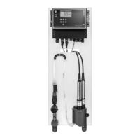
Grundfos DID-3 BF3-FCL2/TCL2/pH Installation And Operating Instructions Manual (412 pages)
Dosing Instrumentation Digital
Brand:
Grundfos
| Category:
Control Unit
| Size: 38 MB
Table of Contents
English
4
1 General Information
4
Table of Contents
4
Symbols Used in this Document
4
Target Group
4
Inspecting the Product
5
2 Safety Instructions
5
Symbols on the Product
5
Transporting the Product
5
Checking the Tightness
6
Hydraulic Connection
6
3 Receiving the Product
5
4 Installation
6
Installation Location
6
Installation of the DID
6
Installing the Sensors
6
5 Starting up the Product
7
Terminal Connection
7
Connecting Further Inputs and Outputs
8
Connecting the CU 382 to the Power Supply
8
Connecting the Sensors to the CU 382 Control Unit
8
Connecting the Valve for Automatic Cleaning
8
Sensor Initialisation
8
Start-Up of the Operating Software
8
6 Electrical Connection
7
Initial Startup
7
7 Storing and Handling the Product
8
Functional Principle
9
Intended Use
9
Product Description
9
8 Product Introduction
9
Identification
10
Display Screen
11
Operating Elements
11
9 Operation
11
Software Overview
12
General Setup
14
Parameter Setup
18
Controller Setup
23
USB Menu / Data Transfer
26
Cleaning
27
10 Maintenance
27
Functional Check
28
11 Fault Finding
29
CU 382 Control Unit
30
Hydraulic Specifications of DID
30
12 Technical Data
30
Dimensions
33
Weights
33
13 Disposal
34
Deutsch
65
1 Allgemeine Informationen
65
Verwendete Symbole
65
Zielgruppe
65
2 Sicherheitshinweise
66
Symbole auf dem Produkt
66
Aufstellungsort
67
Hydraulischer Anschluss
67
3 Produktlieferung
67
Prüfen des Produkts
67
Transportieren des Produkts
67
Erstinbetriebnahme
68
4 Installation
67
Installieren des DID
67
5 Inbetriebnahme des Produkts
68
Montieren der Sensoren
68
Prüfen der Dichtheit
68
6 Elektrischer Anschluss
69
Klemmenanschluss
69
Anschließen der CU 382 an die Stromversorgung
70
Anschließen der Sensoren an die Steuereinheit CU
70
Anschließen des Ventils für die Automatische Reini- Gung
70
Anschließen Weiterer Ein- und Ausgänge
70
Inbetriebnehmen der Betriebssoftware
70
Sensorinitialisierung
70
7 Transport und Handhabung
70
Bestimmungsgemäße Verwendung
71
Funktionsprinzip
71
Produktbeschreibung
71
8 Produkteinführung
71
Produktidentifikation
72
Anzeige
73
Bedienelemente
73
9 Betrieb
73
Software-Übersicht
74
Allgemeine Konfiguration
76
Parameterkonfiguration
80
Reglerkonfiguration
85
USB-Menü/Datenübertragung
88
Reinigung
89
10 Wartung
89
Funktionsprüfung
90
11 Störungssuche
91
Spezifikationen der DID-Hydraulik
92
Steuereinheit CU
92
12 Technische Daten
92
Abmessungen
95
Gewicht
95
13 Entsorgung
96
Español
97
1 Información General
97
Destinatarios
97
Símbolos que Se Emplean en Este Documento
97
2 Instrucciones de Seguridad
98
Símbolos Presentes en el Producto
98
Conexión Hidráulica
99
Inspección del Producto
99
3 Recepción del Producto
99
Transporte del Producto
99
Comprobación de la Estanqueidad
100
Instalación de Los Sensores
100
4 Instalación
99
Instalación del Sistema DID
99
Lugar de Instalación
99
5 Puesta en Marcha del Producto
100
Puesta en Marcha Inicial
100
Conexión de Los Terminales
101
6 Conexión Eléctrica
101
7 Almacenamiento y Manipulación del Producto
102
Conexión de Entradas y Salidas Adicionales
102
Conexión de la Válvula de Limpieza Automática
102
Conexión de Los Sensores a la Unidad de Control CU
102
Conexión del Suministro Eléctrico a la Unidad
102
Inicialización de Los Sensores
102
Puesta en Marcha del Software de Control
102
Descripción del Producto
103
8 Presentación del Producto
103
Principio de Funcionamiento
103
Uso Previsto
103
Identificación
104
Elementos de Control
105
9 Funcionamiento
105
Pantalla
105
Descripción General del Software
106
Configuración General
108
Configuración de Parámetros
111
Configuración de Controladores
116
Menú "Usb"/Transferencia de Datos
120
Limpieza
121
10 Mantenimiento
121
Prueba de Funcionamiento
122
11 Localización de Averías
123
12 Datos Técnicos
124
Especificaciones Hidráulicas del Sistema DID
124
Unidad de Control CU
124
Dimensiones
127
Pesos
127
13 Eliminación
128
Français
160
1 Généralités
160
Public Visé
160
Symboles Utilisés Dans Cette Notice
160
2 Consignes de Sécurité
161
Symboles Sur Le Produit
161
Inspection du Produit
162
3 Réception du Produit
162
Transport du Produit
162
4 Installation
162
Installation du DID
162
Lieu D'installation
162
Raccord Hydraulique
162
5 Démarrage
163
Installation des Capteurs
163
Premier Démarrage
163
Vérification de L'étanchéité
163
Branchement des Bornes
164
6 Branchement Électrique
164
Branchement D'autres Entrées Et Sorties
165
Branchement des Capteurs Au Coffret de Commande CU
165
Connexion du CU 382 À L'alimentation Secteur
165
Démarrage du Logiciel D'exploitation
165
Initialisation du Capteur
165
Raccordement de la Soupape Pour Nettoyage Automa- Tique
165
7 Stockage Et Manutention du Produit
165
Description du Produit
166
Principe de Fonctionnement
166
8 Présentation du Produit
166
Usage Prévu
166
Identification
167
9 Fonctionnement
168
Écran D'affichage
168
Éléments de Fonctionnement
168
Vue D'ensemble du Logiciel
169
Configuration Générale
171
Configuration des Paramètres
175
Configuration du Régulateur
180
Menu USB / Transfert de Données
183
10 Maintenance
184
Nettoyage
184
Vérification du Fonctionnement
185
11 Grille de Dépannage
186
12 Caractéristiques Techniques
187
Coffret de Commande CU
187
Spécifications Hydrauliques du DID
187
Dimensions
190
Poids
190
13 Mise Au Rebut
191
Advertisement
Grundfos DID-3 BF3-FCL2/TCL2/pH Installation And Operating Instructions Manual (38 pages)
Brand:
Grundfos
| Category:
Controller
| Size: 3 MB
Table of Contents
1 General Information
2
Table of Contents
2
Symbols Used in this Document
2
Target Group
2
Inspecting the Product
3
2 Safety Instructions
3
Symbols on the Product
3
Transporting the Product
3
Checking the Tightness
4
Hydraulic Connection
4
3 Receiving the Product
3
4 Installation
4
Installation Location
4
Installation of the DID
4
Installing the Sensors
4
5 Starting up the Product
5
Terminal Connection
5
Connecting Further Inputs and Outputs
6
Connecting the CU 382 to the Power Supply
6
Connecting the Sensors to the CU 382 Control Unit
6
Connecting the Valve for Automatic Cleaning
6
Sensor Initialisation
6
Start-Up of the Operating Software
6
6 Electrical Connection
5
Initial Startup
5
7 Storing and Handling the Product
6
Functional Principle
7
Intended Use
7
Product Description
7
8 Product Introduction
7
Identification
8
Display Screen
9
Operating Elements
9
9 Operation
9
Software Overview
10
General Setup
12
Parameter Setup
16
Controller Setup
21
USB Menu / Data Transfer
24
Cleaning
25
10 Maintenance
25
Functional Check
26
11 Fault Finding
27
CU 382 Control Unit
28
Hydraulic Specifications of DID
28
12 Technical Data
28
Dimensions
31
Weights
31
13 Disposal
32
Advertisement
Related Products
Grundfos DID-3 BF3-FCL2/PH
Grundfos DID-3 BF3-FCL20/PH
Grundfos DID-3 BF3-FCL2/PH/ORP
Grundfos DID-3 BF3
Grundfos DID-3 BF3-PA2/PH
Grundfos DID-3 BF3-PA20/PH
Grundfos DID-3 BF3-ORP/PH
Grundfos DID-3 BT4
Grundfos DID
Grundfos DID-1 BF1-CDI2
Grundfos Categories
Water Pump
Control Unit
Industrial Equipment
Controller
Engine
More Grundfos Manuals
Login
Sign In
OR
Sign in with Facebook
Sign in with Google
Upload manual
Upload from disk
Upload from URL