
Related Manuals for Grundfos DPC 1-1 CSCR


Summary of Contents for Grundfos DPC 1-1 CSCR
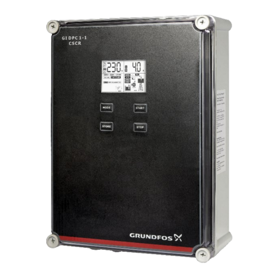
- Page 1 DPC 1-1 CSCR Installation & Operating Instruction DPC CSCR- For Single Phase Pumps, 0.37-2.2 kW For more information contact us: Version: 02.0522...
-
Page 2: Table Of Contents
SAFETY INTRODUCTION Applications Features ------------------------------------------------------------------------------------------- 4 Following are the safety instructions which must be followed by the service Parameter & specifications ----------------------------------------------------------------- 5 partners or user while installing and operating. If ignored, physical injury or even death may happen. Read the safety instructions before handling the INSTALLATION system. -
Page 3: Introduction
PARAMETER AND SPECIFICATIONS: INTRODUCTION Following chart shows main technical parameters & specifications: DPC CSCR is Digital Pump Controller, which is easy to use, programmable device Main technical characteristics for single phase pump, which require both starting capacitor and running Level control (with probes for clear capacitor. -
Page 4: Installation
MEANING OF THE ICONS SHOWN ON THE LCD INSTALLATION Please read this manual carefully before starting installation and operation. Any The parameter configuration icon, damage to the equipment caused due to failure to comply with the descriptions when this icon appears, controller is in in this manual in installation or operation will be beyond the scope of the manual parameter adjustment mode. -
Page 5: Terminals
DIP switch settings Users can set the function switch to suit different applications. Before setting Terminals the function switch; the unit should be disconnected from the power supply. After completing the settings of dip switches, power may be applied to the unit. Following signs will be displayed in voltage displaying area on the LCD conforming to the following list. -
Page 6: Erasing
Again press START key approximately for 3 Pump stops running and parameter secs and release when the unit makes a calibration completed, and LCD screen looks “Beep” sound and a countdown timer as below starts on the LCD screen as shown below INSTALLING LIQUID LEVEL PROBES SWITCH: LIQUID PROBE INSTALLATION Wrap the signal cable &... -
Page 7: Power Connections
POWER CONNECTIONS: Stop Condition: If the water level in the OH tank rises and Float switch is in up position, the pump stops. LCD screen displays FULL, indicating OH tank is full. CONTROL PCB CONNECTIONS: Water Supply (f) Water transfer UG tank to OH tank (using two float switches) Start Condition: If the water level in OH tank falls and the Float switch in OH tank is in down position and the water level in UG tank is high and the Float switch in... -
Page 8: Drainage / De-Watering
Short terminals 1,2,3. Connect common liquid level probe in terminal no. 4 which is placed at the bottom of the tank touching the surface. Connect the lower liquid level probe in terminal no. 5 (this should be ideally at the level where the pump is desired to run). -
Page 9: Pressure Boosting
Pressure Boosting (k) Using 1 pressure switch Pressure switch & 1 float switch Short terminals 1,2,3. Connect common of Pressure Switch in terminal 4, connect NC point of this pressure switch in terminal 5. Kindly ensure Note: If there is no UG tank/ source tank then short terminal 1, 2 and 3 terminal 6 is open. -
Page 10: Basic Operation
BASIC OPERATION Press and hold STOP key and then press STORE key, the product makes a “Beep” sound and displays run hours of the pump since the pump was last calibrated. MANUAL MODE: Press the MODE key to switch to manual mode. Once the unit is in MANUAL mode, press the START... -
Page 11: Communication Link
Basic Function: Computer/SCADA/BMS (Optional) with communication interface can realize long distance monitoring. In the control room, users can realize all the functions of the master controller through the slave controller, except parameter calibration and adjusting. Special Application: As adopting communication interface, the communication distance through wire is less than 1200 meters, whereas for a longer communication distance like mine, water tower, across railway road and bridge etc., users can adopt RS485 extender. -
Page 12: Faults & Protection
NOTE: MEANING OF THE MESSAGES AND GRAPHIC SHOWN ON THE LCD SCREEN: Application: Water Supply/transfer (Using Probes Or Floats) In AUTO mode, if the pump is running and user wants to stop the pump, press the MODE key to switch to MANUAL mode and pump will stop running. F U L L AUTO mode, if the input power gets cut off and when the supply gets... -
Page 13: Application: Pressure Boosting (Using Pressure Switch)
TROUBLE SHOOTING FAULT MESSAGE POSSIBLE CAUSE SOLUTIONS Actual voltage is lower than Check the power supply at source the calibrated voltage, Liquid level in the sump is below the pump inlet, pump stop Flashing of "UNDER V" Control unit will attempt to pump is in under voltage running restart the pump every 5 minutes... - Page 14 Note: Float / Pressure Switch should be ordered separately. Abbreviation: 1. OH : Overhead 2. UG: Underground 3. NO: Normally Open 4. DOL: Direct online start 5. COM: Common...
Need help?
Do you have a question about the DPC 1-1 CSCR and is the answer not in the manual?
Questions and answers