
Related Manuals for Grundfos DPC 1-3


Summary of Contents for Grundfos DPC 1-3
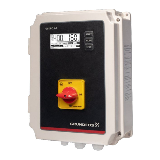
- Page 1 DPC 1-3 Installation & Operating Instruction DPC 1-3 For Three Phase Pumps up to 16A Version: 02.0522 For more information...
-
Page 2: Table Of Contents
SAFETY INTRODUCTION Applications Features ----------------------------------------------------------------------------------------------- 4 Following are the safety instructions which must be followed by the service Parameter & specifications ----------------------------------------------------------------------- 5 partners or user while installing and operating. If ignored, physical injury or even death may happen. Read the safety instructions before handling the INSTALLATION ------------------------------------------------------------------- system. -
Page 3: Introduction
PARAMETER AND SPECIFICATIONS: INTRODUCTION Following chart shows main technical parameters & specifications: DPC is Digital Pump Controller, which is easy to use, programmable device for Main technical characteristics three phase pumps (DOL). It can be used to control the pumps from 1.5 to 16 Level control (with probes for clear Ampere. -
Page 4: Installation
MEANING OF THE ICONS SHOWN ON THE LCD INSTALLATION The parameter configuration icon, when this icon appears, controller is in manual parameter adjustment mode. Please read this manual carefully before starting installation and operation. Any damage to the equipment caused due to failure to comply with the descriptions in this manual in installation or operation will be beyond the scope of the company’s quality guarantee. -
Page 5: Terminals
DIP SWITCH SETTINGS TERMINALS Users can set the function switch to suit different applications. Before setting the function switch; the unit should be disconnected from the power supply. After completing the settings of dip switches, power may be applied to the unit. Following signs will be displayed in voltage displaying area on the LCD Power terminals conforming to the following list. -
Page 6: Erasing
CONNECTIONS Again press START key approximately for 3 Pump stops running and parameter secs and release when the unit makes a calibration completed, and LCD screen looks CONTROLS DEVICES AND APPLICATIONS “Beep” sound and a countdown timer as below starts on the LCD screen as shown below INSTALLING LIQUID LEVEL PROBES SWITCH: LIQUID PROBE INSTALLATION Wrap the signal cable &... -
Page 7: Working Applications
WORKING APPLICATIONS: WATER SUPPLY/TRANSFER BY INSTALLING PROBES OR FLOAT SWITCH Start condition: When the liquid level in overhead tank is below lower probe (in case of float switch, float is down) and liquid level in the underground tank is above lower probe (in case of float switch, float is up), the controller will start “liquid/pressure”... -
Page 8: Pressure Boosting Application By Installing Pressure Switch
PRESSURE BOOSTING APPLICATION BY INSTALLING DRAINAGE APPLICATION BY INSTALING FLOAT SWITCH PRESSURE SWITCH “liquid/pressure” “store”button SWITCH Pressure switch Wiring diagram Adjustable spring “liquid/pressure” “store”button SWITCH Sewage tank Short circuit (g) Application: Pressure boosting (using pressure switch) (h) Application: Irrigation/sewage/drainage (using float switch) Start condition: If the pressure in the pipeline is less than the set point of Start condition:... -
Page 9: Basic Operation
BASIC OPERATION FAULTS AND PROTECTION: During pump running, if dry run, overload, under voltage, over voltage etc. failures happen, the control unit immediately stops the pump, displays it on the MANUAL MODE: LCD screen and automatically executes a check for restarting conditions after a built-in time delay has elapsed. -
Page 10: Application: Sewage/Drainage (Using Floats)
N O W A T E R D R Y R U N Liquid level in the well is below the pump inlet, pump stop running. Liquid level in the lower water tank/water well is below lower sensor/probe (float switch in down position) N O W A T E R APPLICATION: SEWAGE/DRAINAGE (USING FLOATS) Liquid level in the lower water tank/water well is below lower... - Page 11 Liquid level in the well/ Control unit will attempt to restart sump is below the pump the pump every 30 minutes (or set Flashing of "DRY RUN" inlet, pump is in DRY RUN time) until liquid level reaches prevention state above the pump inlet Cut off power supply &...
Need help?
Do you have a question about the DPC 1-3 and is the answer not in the manual?
Questions and answers