
Related Manuals for Grundfos DPC 2-1


Summary of Contents for Grundfos DPC 2-1
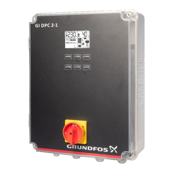
- Page 1 DPC 2-1 Installation and Operating Instructions DPC 2-1 For Single Phase Pumps up to 15A P a g e...
-
Page 2: Table Of Contents
SAFETY INTRODUCTION Applications Features Parameters & Specifications INSTALLATION Tools Used in Controller Installation Controller Components LCD Screen Meaning Of the icons shown In the LCD ------------------------------------------------------ 8 Power Terminal Control PCB connection Installation – Drainage Terminals DIP Switch Settings Electrical Connections Installation –... -
Page 4: Safety
SAFETY Following are the safety instructions which must be followed by the service partners or user while installing & operating the product. If ignored, physical injury or even death may happen. Read the safety instructions before handling the system. WARNING If these safety instructions are not observed, it may result in malfunction or damage to the equipment. -
Page 5: Introduction
INTRODUCTION Thank you for choosing a DPC Series Digital Pump Controller. The Digital Pump Controller model is easy to use, programmable controller and protection device for direct start with single phase two pumps with output power from 0.37kW - 1.5 kW (1.5 - 15A) each. The controller has many operation modes for adapting different pumping applications. -
Page 6: Parameters & Specifications
PARAMETERS AND SPECIFICATIONS: Following chart shows the main technical parameters & specifications: Main Technical Characteristics Double liquid level control Control characteristic Pressure control Working modes Manual / auto By using float switch Drainage application Pressure Boosting application By using pressure switch Water Transfer application By using float switch Main Technical Data... -
Page 7: Installation
INSTALLATION Please read this manual carefully before starting installation and operation. Any damage to the equipment caused due to failure to comply with the descriptions in this manual in installation or operation will be beyond the scope of the company’s quality guarantee. TOOLS USED IN CONTROLLER INSTALLATION: Controller installation and wire installation will need the following tools, you also can choose the right tools according to your own experience. - Page 8 MEANING OF THE ICONS SHOWN ON THE LCD: The parameter configuration icon, when this icon appears, controller is in manual parameter adjustment mode. Time displaying icon, when this icon appears, it mean controller is displaying some parameter of time, eg: pump dry run trip time(units: seconds).
- Page 9 Second Hour Ampere Percent Pump running Pump stopped Low pressure or lack of pressure in the pipeline or pressure tank. High pressure or full of pressure in the pipeline or pressure tank. Pump A Pump B P a g e...
-
Page 10: Power Terminal
POWER TERMINAL CONNECTIONS: Single Phase (without running capacitor) Single Phase (with running capacitor) 10 | P a g e... -
Page 11: Installation - Drainage
CONTROL PCB TERMINAL CONNECTIONS: The control terminal connection varies based on the app INSTALLATION - DRAINAGE: TERMINALS Using one float switch Start condition: If the liquid level in the pit/tank rises, ie. Float A is in up position. Panel will start pump A. - Page 12 Using two float switches Start condition: If the liquid level in the pit/tank rises, ie. Float A is in up position. Panel will start pump A. Panel will alternate between pump A and pump B after previous cycle is completed. LCD screen will display RUN whichever pump in running. If the liquid level in the pit/tank rises even further after first pump is running ie.
- Page 13 Start condition: If the liquid level in the pit/tank rises, ie. Float A is in up position. Panel will start pump A. Panel will alternate between pump A and pump B after previous cycle is completed. LCD screen will display RUN whichever pump in running. If the liquid level in the pit/tank rises even further after first pump is running ie.
-
Page 14: Dip Switch Settings
DIP SWITCH SETTINGS Users can set the function switch to suit different applications. Before setting the function switch, the unit should be disconnected from the power supply. After completing the settings of dip switches, power may be applied to the unit. The symbol corresponding to the application will be displayed on the LCD Screen. - Page 15 Meanings of the messages & graphic shown on the LCD screen Messages & Graphics Description Lack of water in sump water Overflow in sump Overflow 15 | P a g e...
-
Page 16: Installation - Boosting 16 - Terminals
INSTALLATION - BOOSTING: TERMINALS Using 1 Float Switch and 1 Pressure Switch Start condition: If the water level in source tank is high and the float switch A in the source tank is in up position and the Pressure in the line is below the cut-in pressure setting on the pressure switch A the pump starts. - Page 17 Start condition: If the water level in source tank is high and the float switch A in the source tank is in up position and the Pressure in the line is below the cut-in pressure setting on the pressure switch A the pump starts. Panel will alternate between pump A and pump B, when previous demand cycle is completed, and pump(s) have stopped.
-
Page 18: Dip Switch Settings
DANGER Electric shock risk. Before carrying out any installation or maintenance operation, the controller should be disconnected from the power supply and the person should wait at least 2 minutes before opening the controller. Never connect AC power to output L1 & N1 / L2 & N2 terminals. Ensure the motor, controller and power specifications match. - Page 19 Connections for pump over temperature protection (where supplied with pump) Jumpers Lead Pump Shell Pump Shell Over Temperature Over (Thermal)Switch Temperat Pump B Pump A (Thermal) Switch NOTE: To enable the pump’s over temperature protection, connect the pump’s thermistor leads to terminals 14 and 15, 19 and 20 and remove the jumper.
-
Page 20: Installation - Water Transfer
INSTALLATION - WATER TRANSFER: TERMINALS Using 2 Float switch (one float in UG tank, one float in OH tank) Start condition: If water level in UG tank is high ie. Float A is up and water level in OH tank is low ie. - Page 22 Using 3 Float switch (one float in UG tank, two floats in OH tank) Start condition: If water level in UG tank is high ie. Float A is up and water level in OH tank is low ie. Float B is down, panel will start pump A. Panel will alternate between pump A and pump B, after previous cycle is completed.
-
Page 23: Dip Switch Settings
DANGER Electric shock risk. Before carrying out any installation or maintenance operation, the controller should be disconnected from the power supply and one should wait at least 2 minutes before opening the controller. Never connect AC power to output L1&N1 / L2&N2 terminals. Ensure the motor, controller and power specifications. - Page 24 Connections for pump over temperature protection (where supplied with pump) Jumper’s lead Pump shell Pump shell Over temperature (thermal)switch Over temperature (thermal)switch Pump B Pump A NOTE: To enable the pump’s over temperature protection connect the pump’s thermistor leads to terminals 14 and 15, 19 and 20 and remove the jumper.
-
Page 25: Operation
OPERATION BEFORE YOU START - Parameter calibration and erasing To achieve best level of protection of the pump, it is essential that parameter calibration be done immediately after successful pump installation or pump maintenance. PARAMETER CALIBRATION: Pump/s must be able to pump water to enable correct calibration. If pumps are calibrated without water, overload and pump stalled errors may occur Press the A START... -
Page 26: Erasing Former Parameters
ERASING FORMER PARAMETERS: When pump is reinstalled after maintenance or a new pump is installed, user must erase the former calibration and a new calibration must be done. ERASING THE PARAMETER CALIBRATION: 2. Press the A STOP key for 3 seconds; 1. -
Page 27: Switching To Manual Mode
SWITCH TO MANUAL MODE: To switch from Auto mode to manual mode, and if the controller is under Auto screen lock, then press MODE and STORE button simultaneously until the countdown timer stops and mode switches back to manual. Press the START key to start the pump and the STOP key to stop the pump. -
Page 28: Pump Accumulative Running Time
NOTE: The failure displayed above is PUMP STALLED. Repeat for pump B by using B STOP key. PUMP ACCUMLATIVE RUNNING TIME: The controller can memorize how many hours that pump has run, so it is very convenient for the pump user to analyze the pump running conditions and do maintenance. -
Page 29: Communication Link
COMMUNICATION LINK The controller has communication interface, between the pump controller and computer/SCADA/BMS, users can realize a long-distance monitoring function. This function applies to where the controller is installed in the basement or pumping room, but users require to monitor and control the pump on the ground or in a control room. -
Page 30: Technical Parameters
TECHNICAL PARAMETER: The following chart shows main technical parameters of communication between the pump controller and Computer/SCADA/BMS. Main Technical Data Physical interface RS485 Bus Interface: asynchronous semi duplex 1 start bit, 8 data bit, 1 stop bit, no verify Data format 1 start bit, 8 data bit, 2 stop bit, no verify Default: 1 start bit, 8 data bit, 1 stop bit, no verify 1200,2400,4800,9600 bps (default 9600bps) -
Page 31: Trouble Shooting
TROUBLE SHOOTING GUIDE Fault message Possible cause Solutions The real running voltage is Report low line voltage to the Flashing of UNDER V lower than the set voltage, power supply company. pump is in under voltage protection state. Control will attempt to restart the pump every 5 min until line voltage is restored to normal. - Page 32 Version: 02.0522...
Need help?
Do you have a question about the DPC 2-1 and is the answer not in the manual?
Questions and answers