Table of Contents
Advertisement
Quick Links
Advertisement
Table of Contents

Subscribe to Our Youtube Channel
Related Manuals for Grundfos Conex DIS-2Q


Summary of Contents for Grundfos Conex DIS-2Q
- Page 1 GRUNDFOS INSTRUCTIONS Conex DIS-2Q ® Installation and operating instructions...
-
Page 2: Table Of Contents
Parameter settings General information Warning Applications These complete installation and operating instructions are also Safety instructions available on www.grundfos.com. Obligations of the owner Prior to installation, read these Avoiding danger installation and operating instructions. Identification Installation and operation must comply... -
Page 3: Parameter Settings
2. Parameter settings Controller settings 1st level 2nd level 3rd level Measured value Code functions Code number Hysteresis Device number for RS-485 Code Switching point SP 1 Pulse frequency for SP 1 Transmits alarm via RS-485 x 100 SP 1 01 (yes) pulses/ 00 (no) -
Page 4: General Information
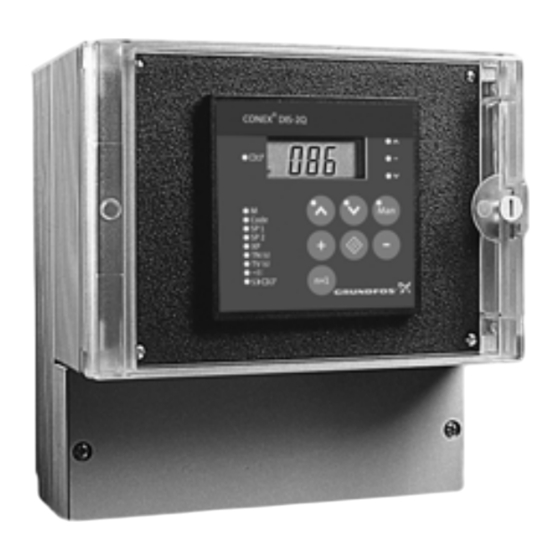
230/240V 50/60Hz 8 VA, IP 65 please contact Grundfos. Conex DIS-2Q 96732494P1108270861557 4. Applications The Conex DIS-2Q is a multipurpose device designed to carry out high-precision controls of disinfection parameters, pH-value and redox potential. Conex DIS-2Q microprocessor-based controllers Fig. 1... -
Page 5: General Data
7.2 General data 7.3.2 Controller functions • Limit contact Input power Approximately 8 VA • continuous controller Permissible • two-position controller ambient 0 to 50 °C • three-position controller temperature Control functions proportional controller Permissible • ratio controller storage -20 to +65 °C •... -
Page 6: Interface
Fig. 3 Conex DIS-2Q in wall mounting housing the control panel. 2. Slip on the supplied gasket. 3. Insert the Conex DIS-2Q into the opening from the front. Do not damage the gasket! Caution The gasket must be fitted exactly! 1. -
Page 7: Installation In Wall Housing
9. Electrical connection 8.5 Installation in wall housing The plastic housing is designed for the Warning Conex DIS-2Q controller and is very easy to install and service. Disconnect the mains voltage before connecting the power supply cable and – 300-115 (91835231) for one Conex DIS-2Q... -
Page 8: Terminals
27 28 29 30 31 32 mA 1 mA 2 100 % mA 2 mA 1 RS 485 Fig. 5 Terminals Conex DIS-2Q Pos. Description External inputs mA 1 Current input 1 (measured variable) mA 2 Current input 2 (disturbance variable or command variable) -
Page 9: Power Supply Connection
9.1.1 Cable types and length 9.3.3 Current output 1 (measured value) Current 1 output outputs the displayed measured Max. length value as an analog current (0 (4) to 20 mA). Cable Conductors Screen Use of current signal: • As input signal for another indicator. 1,000 Single Make sure that the polarity of the... -
Page 10: Relay Outputs
9.5 Relay outputs The connection of the relay outputs depends on the application and the final control elements used. Therefore consider the connections described below as guidelines. Note 15.2 Application examples of different output signals and final control elements and the documentation of the final control element. -
Page 11: Operation
10.1.1 Application example The controller is used e.g. in conjunction with other 10.1 Function Grundfos products to control the dosing of chlorine and to correct the pH value. Conex DIS-2Q is a configurable, microprocessor- based controller for exact control of any measured This is only one of a multitude of variables. - Page 12 – Measures the water flow. – Outputs this value as a signal of 0 (4) to 20 mA, • The Conex DIS-2Q controller: – Calculates the manipulated variable signal from the measured concentration of chlorine and the signal from the electromagnetic flowmeter.
-
Page 13: Controls And Displays
"Function" key • Switch to next function. "+" key • Increase value to be set. Fig. 8 Front of Conex DIS-2Q Pos. Description Control elements • LEDs to display the control deviation: The combination of illuminating and flashing LEDs indicates the magnitude of... -
Page 14: Operating The Controller
10.3 Operating the controller This combination means: Keep the first key pressed and then briefly press the Note second key. 1st level 3rd level 2nd level Display measured Display and set code value (actual value) functions. in %. Enter code number. Display and set Display and set hysteresis. - Page 15 10.3.1 Basic settings for the controller functions All parameters are factory-set to zero. A setting is always required prior to startup. Note 10.3.6 Summary of code functions 15.2 Application examples of different output signals and final control elements Limit Two- Two-position Three- Three-...
- Page 16 10.3.2 Setting and displaying codes 10.3.4 Switching the code functions on and off The code function is used to protect the device against unintentional or unauthorised adjustment. XX.X • If settings on the device are to be changed: Currently set Lowest code function that is...
- Page 17 10.3.5 Scanning the active code functions Alarm relay Only functions that XX.X are on are Alarm relay is energised permanently displayed. on alarm. Alarm relay is energised for approximately 1 second (momentary pulse), e.g. to trigger an alarm recorder. Proportional action control for switching point 1 Switching point 1 with proportional action control.
- Page 18 Disturbance variable feedforward Controller configuration Without disturbance variable OFF Device operates as setpoint controller. feedforward. Device operates as ratio controller. With disturbance variable feedforward. Setpoint is entered via current input 2. Enabling of third operator level Assignment of LEDs for display of control deviation OFF Third operator level disabled.
- Page 19 10.3.7 Settings for switching point SP 1 Displaying and setting pulse frequency for switching point 1 • Display and set switching point SP 1. Range of adjustment: 0.1 (correlates with 10 pulses/ hour) to 72 (correlates with 7,200 pulses/hour). Current setpoint 31.0 If 0 is set as the pulse frequency, the Note...
- Page 20 Selecting proportional action control for Displaying and setting pulse frequency for switching point 2 switching point 2 • Select code function 7: Range of adjustment: 0.1 (correlates with 10 pulses/ hour) to 72 (correlates with 7,200 pulses/hour). – OFF: Switching point 2 with proportional action control.
- Page 21 10.3.11 Displaying and setting reset time Range of adjustment: T = 0 to 1,999 s. If the reset time is 0, the device operates as a proportional action controller (only P action). Note This is not possible if the device is to Current 18.0 be used as a three-position step...
- Page 22 10.3.13 Displaying and setting interpulse period 10.3.15 Displaying and setting minimum pulse width Range of adjustment: 1 to 99 s. Range of adjustment: 0 to 9.9 s. If the pulse frequency is 0, the device Note operates as an interpulse controller. Current setpoint Current...
- Page 23 10.3.18 Set current input 2 (disturbance variable/ 10.3.19 Setting current output 1 (control output command variable) for SP 1) Selecting signal Selecting signal • Select code function 13: • Select code function 19: – OFF: Signal 0 to 20 mA. –...
- Page 24 • Open the servomotor completely using the "Up" button. 0:98 1:00 Upper setpoint is set to 100 %. Fig. 31 Opening the servomotor • Switch off code function 15. – The colon no longer flashes in the display. 10.3.22 Settings for RS-485 interface Displaying and setting device number •...
- Page 25 Switch transmission of alarms on and off • Switch on code function 15. – A colon flashes in the display. 0:0.0 Current status (00 or 01) Alarms are not Alarms are transmitted. transmitted. Save status. Fig. 33 Switching transmissions of alarms •...
-
Page 26: Fault Finding
Mains fuse SI2: 1. Use the public or private waste collection service. – Backup fuse for measuring amplifier 2. If this is not possible, contact the nearest Grundfos company or service workshop. – 4 A slow-blow fuse – order No. 96726014. Warning... -
Page 27: Appendix
15. Appendix Manipulated variable The manipulated variable is the dosed quantity of 15.1 Measuring and control technology chlorine. Final control element 15.1.1 Terminology The final control element that changes the Below you find explanations on the terminology used manipulated variable e.g. a chlorine gas dosing within the measuring and control technology. - Page 28 Closed-loop control In a closed-loop control, the controlled variable is measured and the result, the actual setpoint, is sent to the controller. The actual value is compared with the setpoint. Then the manipulated variable is calculated in order to bring the controlled variable back to the setpoint.
- Page 29 15.1.3 Design and function of a controller The controller calculates the manipulated variable for the setpoint and the actual value. Based on the setpoint and the actual value, the controller generates an output signal which the corresponding final control element processes. Fig.
- Page 30 If T magnitude of the deviation linearly influences the manipulated variable. ∞ In the setting of Conex DIS-2Q, T The upper limit is only limited by the maximum of the Note is often printed as T = 0 for technical final control element.
- Page 31 Manipulated variable Manipulated variable max. Time Time Manipulated variable Manipulated variable max. max. action action action action action Time Time Fig. 39 Integral action Fig. 40 Differential action Differential action, PID action 15.1.5 Adaptation and error correction With a differential action (D) controller, a deviation When adapting the controller to the controlled initially generates a very high manipulated variable system, use the basic parameter settings gained...
- Page 32 Manipulated variable Manipulated variable Time Time Fig. 42 too small Fig. 45 too large • The controlled variable reaches the setpoint very 15.1.6 Control modes for dosing applications slowly: Proportional control – The reset time T is too large. The purpose is to chlorinate a flow of water uniformly.
- Page 33 Measuring amplifier Open-loop controller Dosing unit with servomotor Conex DIA-1 Alar CONEX DIS-2Q CONEX DIS-2Q Dosing unit with CODE SP 1 SP 2 TV (s) TN (s) CODE SP 1 servomotor SP 2 TV (s) TN (s) Closed-loop controller Measuring...
-
Page 34: Application Examples Of Different Output Signals And Final Control Elements
15.2 Application examples of different 15.2.1 Limit contact controller output signals and final control Application elements • Upward control direction of chlorine concentration using chlorine bleaching leach. The purpose of the output module of the controller is to convert the calculated manipulated variable into a •... - Page 35 Connection diagram 15 16 17 18 19 20 21 22 23 24 25 26 L1 N PE L1 N PE Fig. 52 Connection diagram for dosing pump Pos. Description Free relay outputs Dosing pump Power supply...
- Page 36 15.2.2 Two-position interpulse controller for chlorine Application – Dosing pump for chlorine bleaching leach is switched on for brief periods. • Upward control direction of the chlorine concentration using the chlorine bleaching. • The measured value deviates from the setpoint: •...
- Page 37 Connection diagram 15 16 17 18 19 20 21 22 23 24 25 26 L1 N PE L1 N PE Fig. 54 Connection diagram for dosing pump Pos. Description Free relay outputs Dosing pump Power supply...
- Page 38 15.2.3 Two-position interpulse controller for pH Application – Dosing pump for acid is switched on for brief periods. • Downward control direction of pH value using acid. • The measured value deviates from the setpoint: • Control of the dosing pump by power supply. –...
- Page 39 With upward control direction using Note leach: Switch on code function 1. Connection diagram 15 16 17 18 19 20 21 22 23 24 25 26 L1 N PE L1 N PE Fig. 56 Connection diagram for dosing pump Pos. Description Free relay outputs Dosing pump...
- Page 40 15.2.4 Two-position pulse frequency controller for chlorine Application – Dosing pump for chlorine bleaching leach carries out individually controlled dosing • Upward control direction of chlorine strokes. concentration using chlorine bleaching leach. • The measured value deviates from the setpoint: •...
- Page 41 Connection diagram 15 16 17 18 19 20 21 22 23 24 25 26 L1 N PE L1 N PE Fig. 58 Connection diagram for dosing pump, contact input Pos. Description Free relay outputs Dosing pump Power supply Contact input...
- Page 42 15.2.5 Two-position pulse frequency controller for pH Application – Dosing pump for acid carries out individually controlled dosing strokes. • Downward control direction of pH value using acid. • The measured value deviates from the setpoint: • Control of dosing pump via contact input. –...
- Page 43 With downward control direction using Note leach: Switch on code function 1. Connection diagram 15 16 17 18 19 20 21 22 23 24 25 26 L1 N PE L1 N PE Fig. 60 Connection diagram for dosing pump, contact input Pos.
- Page 44 15.2.6 Dual two-position pulse frequency controller Application – Dosing pump for acid carries out individually controlled dosing strokes. • Setpoint control of pH value using acid and leach. • The actual value of switching point 2 falls below the setpoint: •...
- Page 45 Parameter settings Required pH value: e.g. pH 7.00. SP 1 Above the required pH value, e.g. 52 % (correlates with pH 7.28). 72 (maximum value (correlates with 7,200 strokes per hour). Pulse frequency for SP 1 The dosing capacity of the pump is then fully utilised. SP 2 Below the required pH value, e.g.
- Page 46 15.2.7 Dual two-position interpulse controller Application • The actual value of switching point 1 exceeds the setpoint: • Setpoint control of pH value using acid and leach. – Dosing pump for acid is switched on for brief periods. • Control of dosing pumps by power supply. •...
- Page 47 Parameter settings Required pH value, e.g. pH 7.00. SP 1 Above the required pH value, e.g. 52 % (correlates with pH 7.28). Pulse frequency for SP 1 SP 2 Below the required pH value, e.g. 48 % (correlates with pH 6.72). Pulse frequency for SP 2 According to local conditions, e.g.
- Page 48 15.2.8 Three-position step controller Application – Set the servomotor of the dosing pump or chlorine gas dosing unit to minimum. • Upward control direction of chlorine concentration using chlorine bleaching leach or • The actual value of the required chlorine chlorine gas.
- Page 49 Connection diagram 15 16 17 18 19 20 21 22 23 24 25 26 1 S1 L1 N PE Fig. 66 Connection diagram for servomotor Pos. Description Free relay outputs Servomotor Power supply Open Close...
- Page 50 15.2.9 Three-position proportional controller Application • When the flow of water increases: • Open-loop control of dosed chlorine proportional – The servomotor moves in direction of the to the flow. increased dosing capacity. • When the flow of water decreases: Description –...
- Page 51 Connection diagram 3 4 5 6 7 8 9 10 11 12 13 14 15 16 17 18 19 20 21 22 23 24 25 26 1 S1 L1 N PE (0 %) (100 %) Fig. 68 Connection diagram for feedback potentiometer, servomotor Pos.
- Page 52 15.2.10 Three-position step controller with disturbance variable feedforward Application • When the flow of water increases: • Open-loop control of dosed chlorine proportional – The servomotor moves in the direction of the to the flow and closed-loop control dependent on increased dosing capacity.
- Page 53 Connection diagram 1 2 3 4 5 6 7 8 9 10 11 12 13 14 15 16 17 18 19 20 21 22 23 24 25 26 L1 N PE (0 %) (100 %) Fig. 69 Connection diagram for feedback potentiometer, servomotor, measuring amplifier Pos.
- Page 54 15.2.11 Continuous controller Application – The continuous current signal is generated proportional to the deviation from the setpoint. • Upward control direction of chlorine concentration using chlorine bleaching leach. • Response of the dosing pump with increasing deviation from the setpoint: •...
- Page 55 Connection diagram 1 2 3 4 5 6 7 8 9 10 11 12 13 14 15 16 17 18 19 20 21 22 23 24 25 26 L1 N PE L1 N PE Fig. 71 Connection diagram for dosing pump, current input Pos.
- Page 56 15.2.12 Continuous controller with disturbance variable feedforward Application • When the flow of water increases: • Open-loop control of dosed chlorine proportional – The current signal increases. to the flow and closed-loop control dependent on • When the flow of water decreases: the measured value.
- Page 57 Connection diagram 1 2 3 4 5 6 7 8 9 10 11 12 13 14 15 16 17 18 19 20 21 22 23 24 25 26 L1 N PE L1 N PE Fig. 72 Connection diagram for dosing pump, current input, measuring amplifier Pos.
-
Page 58: Serial Interface
15.3 RS-485 serial interface If the operation mode is "automatic" and no alarm indication is present, a Conex DIS-2Q controller 15.3.1 Hardware answers with code "54". If an indication is present, the code "5C" is transmitted. Now you can read the... - Page 59 • Answer of the selected device: Transmitted ASCII Device type Device code Hex code Function hex code character Conex DIS-2Q Value of the selected without function SP1 as binary (35H), (34H) indication number without (30H, 30H, present 0038 decimal point:...
- Page 60 Functions list • State identifier (alarm list) • General functions Function Function Function Dosing alarm number State identifier (bit-oriented alarm list Input control stop see below) Automatic mode of controller Serial number of the device Dosing alarm: change recognized Software state (month, year) Manufacturing date (month, year) Input control stop: change recognized Measuring input 1 in mV...
- Page 61 Declaration of conformity GB: EC declaration of conformity CZ: ES prohlášení o shodě We, Grundfos, declare under our sole responsibility that the product My firma Grundfos prohlašujeme na svou plnou odpovědnost, ® ® Conex DIS-2Q, to which this declaration relates, is in conformity with že výrobek Conex...
- Page 62 Argentina China Germany Bombas GRUNDFOS de Argentina S.A. Grundfos Alldos GRUNDFOS GMBH Ruta Panamericana km. 37.500 Centro Dosing & Disinfection Schlüterstr. 33 Industrial Garin ALLDOS (Shanghai) Water Technology 40699 Erkrath 1619 - Garin Pcia. de B.A. Co. Ltd. Tel.: +49-(0) 211 929 69-0 Phone: +54-3327 414 444 West Unit, 1 Floor, No.
- Page 63 Telefax: +66-2-725 8998 Fax: + 370 52 395 431 Phone: +381 11 26 47 877 / 11 26 47 Turkey Malaysia GRUNDFOS POMPA San. ve Tic. Ltd. Telefax: +381 11 26 48 340 GRUNDFOS Pumps Sdn. Bhd. Sti. Singapore 7 Jalan Peguam U1/25 Gebze Organize Sanayi Bölgesi...
- Page 64 96681488 0714 ECM: 1111485 www.grundfos.com...
Need help?
Do you have a question about the Conex DIS-2Q and is the answer not in the manual?
Questions and answers