
Related Manuals for Grundfos DPC CSIR


Summary of Contents for Grundfos DPC CSIR
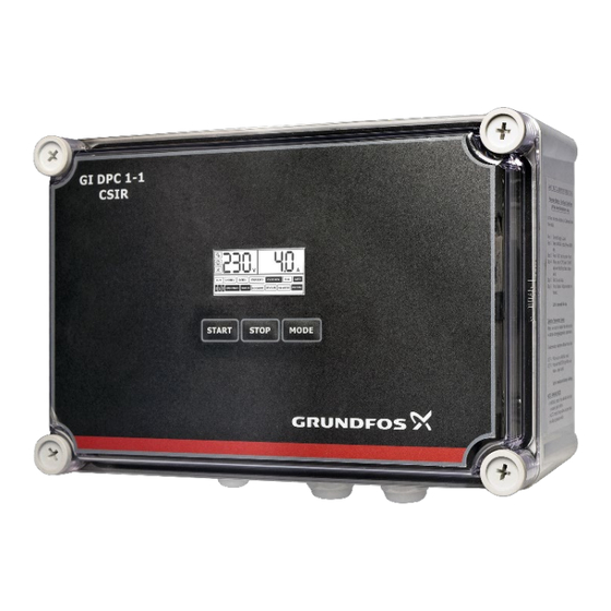
- Page 1 DPC CSIR Installation & Operating Instruction DPC CSIR- For Single Phase Pumps, 0.37-1.1 kW Version: 02.0522...
-
Page 2: Table Of Contents
SAFETY INTRODUCTION Applications Features ------------------------------------------------------------------------------------------- 4 Following are the safety instructions which must be followed by the service Parameter & specifications ------------------------------------------------------------------ 5 partners or user while installing and operating. If ignored, physical injury or even death may happen. Read the safety instructions before handling the INSTALLATION system. -
Page 3: Introduction
PARAMETER AND SPECIFICATIONS: INTRODUCTION Following chart shows main technical parameters & specifications: DPC CSIR is the Digital pump controller with a starting capacitor for single phase Main technical characteristics pumps. Its rated output power ranges from 0.37 - 1.1 KW. -
Page 4: Installation
MEANING OF THE ICONS SHOWN ON THE LCD INSTALLATION Please read this manual carefully before starting installation and operation. Any The parameter configuration icon, damage to the equipment caused due to failure to comply with the descriptions when this icon appears, controller is in in this manual in installation or operation will be beyond the scope of the manual parameter adjustment mode. -
Page 5: Terminals
DIP switch settings Users can set the function switch to suit different applications. Before setting Terminals the function switch; the unit should be disconnected from the power supply. After completing the settings of dip switches, power may be applied to the unit. Following signs will be displayed in voltage displaying area on the LCD conforming to the following list. -
Page 6: Erasing
Again press START key approximately for 3 Pump stops running and parameter secs and release when the unit makes a calibration completed. LCD screen display- “Beep” sound and a countdown timer looks as below starts on the LCD screen as shown below INSTALLING LIQUID LEVEL PROBES SWITCH: LIQUID PROBE INSTALLATION Wrap the signal cable &... -
Page 7: Power Connections
POWER CONNECTIONS: Stop Condition: If the water level in the OH tank rises and Float switch is in up position, the pump stops. LCD screen displays FULL, indicating OH tank is full. CONTROL PCB CONNECTIONS: Water Supply (f) Water transfer UG tank to OH tank (using two oat switches) Start Condition: If the water level in OH tank falls and the Float switch in OH tank is in down position and the water level in UG tank is high and the Float switch in... -
Page 8: Drainage / De-Watering
Short terminals 1,2,3. Connect common liquid level probe in terminal no. 4 which is placed at the bottom of the tank touching the surface. Connect the lower liquid level probe in terminal no. 5 (this should be ideally at the level where the pump is desired to run). -
Page 9: Pressure Boosting
Pressure Boosting (j) Using 1 pressure switch (j)Pressure switch & 1 f l oat switch Short terminals 1,2,3. Connect common of Pressure Switch in terminal 4, connect NC point of this pressure switch in terminal 5. Kindly ensure Note: If there is no UG tank/ source tank then short terminal 1, 2 and 3 terminal 6 is open. -
Page 10: Basic Operation
FAULTS AND PROTECTION: BASIC OPERATION During pump running, if dry run, overload, under voltage, over voltage etc. failures happens, the control unit immediately stops the pump, displays it on the LCD screen and automatically executes a check for restarting conditions MANUAL MODE: after a built in time delay has elapsed. -
Page 11: Application: Sewage/Drainage (Using Floats)
Application: pressure Boosting (Using Pressure Switch) N O W A T E R F U L L Liquid level in the lower water tank/water well is below lower sensor/probe (float switch in down position) If there is full pressure in the pipeline or pressure tank, contact point Application: sewage/drainage (USING FLOATS) of pressure switch is OFF then pump stop running F U L L... - Page 12 Actual drawn current is Control unit will attempt to higher than the calibrated restart the pump every current, pump is in over load 30 minute until running current protection state is restored to normal Flashing of "OVER LOAD" Pump impeller is jammed/ pump motor dragging/ Check pump impeller or bearing pump bearing broken...
Need help?
Do you have a question about the DPC CSIR and is the answer not in the manual?
Questions and answers