
Related Manuals for Grundfos DPC 1-1


Summary of Contents for Grundfos DPC 1-1
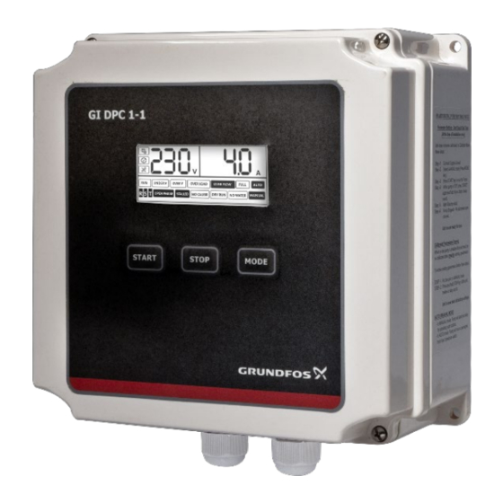
- Page 1 DPC 1-1 Installation & Operating Instruction DPC 1-1- For Single Phase Pumps, up to 15A For more information contact us: Version: 02.0522...
- Page 2 SAFETY INTRODUCTION Applications ------------------------------------------------------------------------------------------ 4 Following are the safety instructions which must be followed by the service partners or user while installing and operating. If ignored, physical injury or Features -----------------------------------------------------------------------------------------------4 even death may happen. Read the safety instructions before handling the Parameter &...
- Page 3 PARAMETER AND SPECIFICATIONS: INTRODUCTION Following chart shows main technical parameters & specifications: DPC is Digital Pump Controller, which is easy to use, programmable device for Main technical characteristics single phase pumps (monoblock or submersible). It can be used to control the Level control (with probes for clear pumps up to 15 Ampere.
-
Page 4: Installation
INSTALLATION LCD SCREEN Please read this manual carefully before starting installation and operation. Any Minute damage to the equipment caused due to failure to comply with the descriptions in this manual in installation or operation will be beyond the scope of the company’s quality guarantee. -
Page 5: Control Terminals
PARAMETER TERMINALS CALIBRATION AND ERASING Please read this manual carefully before starting installation and operation. Any Power terminals damage to the equipment caused due to failure to comply with the descriptions in this manual in installation or operation will be beyond the scope of the company’s quality guarantee. - Page 6 CONNECTIONS CONTROLS DEVICES AND APPLICATIONS INSTALING LIQUID LEVEL PROBES SWITCH: ERASING: LIQUID PROBE INSTALLATION Wrap the signal cable & down-lead of sensor In the event of risk of electric This needs to be done whenever pump is repaired or a new pump is installed, Focation cone storms (lightning) or when liquid previous parameters needs to be erased before the unit is re-calibrated.
-
Page 7: Start Condition
WORKING APPLICATIONS: WATER SUPPLY/TRANSFER BY INSTALLING PROBES OR FLOAT SWITCH Start condition: When the liquid level in overhead tank is below lower probe (in case of float switch, float is down) and liquid level in the underground tank is above lower probe (in case of float switch, float is up), the controller will “liquid/pressure”... - Page 8 PRESSURE BOOSTING APPLICATION BY INSTALLING DRAINAGE APPLICATION BY INSTALLING FLOAT SWITCH PRESSURE SWITCH “liquid/pressure” Wiring diagram “store”button SWITCH Pressure switch Wiring diagram Internal capacitance Adjustable spring N1 L1 C “liquid/pressure” Internal capacitance “store”button SWITCH N1 L1 C L PE Short circuit Sewage tank Pump AC200V...
-
Page 9: Basic Operation
BASIC OPERATION MANUAL MODE: Press the MODE key to switch to manual mode. Once the unit is in MANUAL FAULTS AND PROTECTION: mode, press the START key to run pump, press the STOP key to stop pump. During pump running, if dry run, overload, under voltage, over voltage etc. failures happen, the control unit immediately stops the pump, displays it on the NOTE: In manual state, the unit doesn’t receive signal from float... - Page 10 This type of motor does not require the starting capacitor. It only requires the running capacitor. The ratings of the capacitors are explained in the below table. Grundfos recommends using only the capacitors as per the below mentioned ratings and the capacitor must be installed as per the guidelines mentioned below.
-
Page 11: Troubleshooting
TROUBLE SHOOTING FAULT MESSAGE POSSIBLE CAUSE SOLUTIONS Actual voltage is lower than Check the power supply the calibrated voltage, at source Flashing of "UNDER V" pump is in under voltage protection state Check the power supply at source Actual voltage is higher Control unit will attempt than the calibrated voltage, Flashing of "OVER V"...
Need help?
Do you have a question about the DPC 1-1 and is the answer not in the manual?
Questions and answers