
Related Manuals for Grundfos DID BF1


Summary of Contents for Grundfos DID BF1
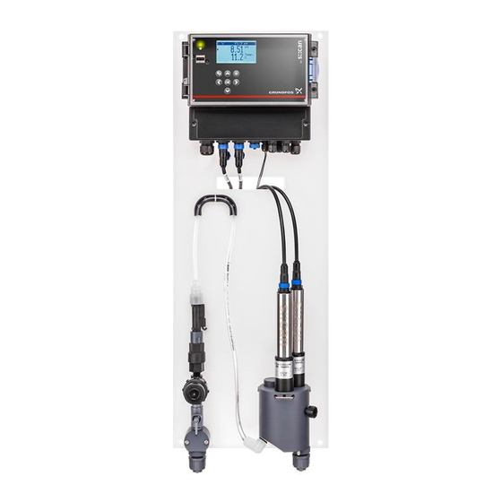
- Page 1 GRUNDFOS INSTRUCTIONS Installation and operating instructions Other languages http://net.grundfos.com/qr/i/99037650...
-
Page 2: Table Of Contents
English (GB) Installation and operating instructions 1. General information Original installation and operating instructions These installation and operating instructions describe Grundfos 1.1 Target group DID (Dosing Instrumentation Digital). Sections 1-6 give the information necessary to be able to unpack, 1.1.1 Qualification and training install and start up the product in a safe way. -
Page 3: Safety Instructions
2. Safety instructions 4. Installation WARNING WARNING Electric shock Electric shock - Switch off the power supply before connecting the - Switch off the power supply before installation. power supply cable and relay contacts. - IP65 only applies, if the housing cover and the - Do not dismantle the control unit. -
Page 4: Installing The Sensors
4.3.1 Installing the measuring water inlet and outlet 5. Starting up the product 1. Remove the blind plugs from the inlet thread and the outlet 5.1 Initial startup thread of the flow cell. WARNING Electric shock - Switch off the power supply before startup. - IP65 only applies, if the housing cover and the terminal compartment of the CU 382 are properly closed, and the appropriate cable glands or... -
Page 5: Connecting The Sensors To The Cu 382 Control Unit
Description and use of the terminals 6.2 Connecting the sensors to the CU 382 control unit All sensors for the DID have plugs. Terminal Description Sensors for immersion have fixed cables with plugs. Phase 1. Make sure that the sensor plug and the socket of the CU 382 Power supply Neutral control unit are dry and clean. -
Page 6: Storing And Handling The Product
7. Storing and handling the product • Before storing the DID, empty all pipes, hoses and flow cells, remove the sensors and pack them separately. • Observe the permissible ambient conditions. See section 12. Technical data. • Do not expose the DID to strong impact, mechanical loads or vibrations. -
Page 7: Intended Use
8.2 Intended use The DID is designed for online monitoring of water quality parameters and offers control functions for these parameters. The DID must be used in accordance with the instructions given in this manual. The values mentioned in this manual must be observed. -
Page 8: Operation
9. Operation 9.1 Operating elements Fig. 8 CU 382 operating elements Pos. Description Power LED, green Communication LED, orange • Flashes during communication with a sensor. USB slot Display Operating buttons [Back] button • Exits the current menu [Up] button •... -
Page 9: Software Overview
9.2 Software overview The CU 382 has four different screens and menus, which can be selected by the [Right] and [Left] buttons. The default screen is the "Parameter" screen. When pressing the [Back] button several times in a submenu, you come back to one of the following screens: Status Parameter Controller... -
Page 10: General Setup
9.2.3 Controller screen 9.3 General setup Up to 3 controllers can be configured and displayed. In the "Setup" menu, general settings can be made. Scroll through the list of controllers with the [Up] and [Down] • Press the [Function] button in the status screen to open the buttons. - Page 11 Sensor configuration Removing a sensor • Select a sensor or an input with the [UP] and [DOWN] buttons. 1. Select "Remove" with the [Up] and [Down] buttons. Confirm with [OK]. 2. Confirm with [OK]. – The "Sensor configuration" menu opens. The sensor and the parameters for the sensor are removed.
- Page 12 9.3.5 MODBUS slave 9.3.3 Measurement settings If the CU 382 is used as a Modbus slave, the connection settings Meas. settings can be configured in the "MODBUS slave" menu. Interval [s] : ► MODBUS slave Address: ► Parity: Baudrate: 38400 Time between two measurements in a range of "Interval [s] :"...
-
Page 13: Parameter Setup
9.3.8 Service ∧ P1 FCL/mg/l Setup Output: 4-20mA #1 ► Access code: ► 0001 Output settings... pH compensation... Parameter info... Remove parameter Use the "Access code:" "0001" to open the "Service" menu. Submenu Settings "Calibrate expert..." Calibrate a parameter Service ∨... - Page 14 6. Select "Sample 1 :" with the [Up] and [Down] buttons. Confirm "Offset" calibration with [OK]. P2 Calibrate expert... ∨ – The measured raw value is shown and stored in the sensor. Type: Local 7. Carefully rinse the sensor with distilled water three times ►...
- Page 15 9.4.3 Display settings... Performing "Span" calibration In the "Display settings..." menu the appearance of the parameter The "Span" calibration is an in-situ calibration. The sensor must not be removed from the flow cell. on the parameter screen and in the stored parameter files can be configured.
- Page 16 Analog outputs P2 Alarm settings... P2 Output settings... Require ack.: ► [4mA]: Al. lower: ► 0.00 [20mA]: Al. upper: 14.00 Output: None Use Sys-Error: "Require ack.:" Acknowledgement of an alarm "Al. lower:" "[4mA]:" The parameter value for 4 mA Lower limit for an alarm "Al.
- Page 17 PULSE Assigning the parameter value for 100 % output 1. Select "[100%]:" with the [Up] and [Down] buttons. Confirm P2 Output settings... with [OK]. Type: PULSE ► 2. Change the parameter value for 100 % output with the [Up], [0%]: 0.00 [Down], [Left] and [Right] buttons.
-
Page 18: Controller Setup
9.5.1 Setpoint... Enabling the pH compensation 1. Select "Type:" with the [Up] and [Down] buttons. Confirm with The setpoint of the controller can be defined directly in the [OK]. operating software of the controller, or an external setpoint adjustment can be configured. A setpoint can be controlled by an 2. - Page 19 Disturbance control "Kp [%]:" The proportional part of the PID controller with a The function of disturbance control (compound-loop control) is range of 0 to 100 % defined by following equation: "Ti [s]:" The integral part of the PID controller with a range Controller output value with disturbance control = controller of 1 to 3000 seconds.
- Page 20 Changing the controller type C2 Output settings... 1. Select "Type:" with the [Up] and [Down] buttons. Confirm with Type: ► [OK]. Period [s]: 2. Select "PID", "2-P" or "None" with the [Up] and [Down] buttons. Confirm with [OK]. – "None" deactivates the controller. Changing the hysteresis of the controller 1.
-
Page 21: Alarm Setup
9.5.6 Stop on Alarm: 9.7 USB menu / Data transfer The USB menu is activated when an USB stick is plugged in the C2 Stop on Alarm: ∨ USB slot. ► FCL: ------------ USB data transfer Up/Low Copy results ► Temp.: Upper Delete results... -
Page 22: Maintenance
9.7.1 Result file 10. Maintenance The result file is in .txt format and structured as follows: WARNING Electric shock Timestamp Seconds since 1970/1/1 - Switch off the power supply before connecting the Time YearMonthDay-HourMinuteSecond power supply cable and relay contacts. - Do not dismantle the control unit. -
Page 23: Functional Check
10.2 Functional check A functional check can be required for one of the following reasons: • Initial startup • Routine • Malfunction • Modification of the DID setup (e.g. integration of an additional sensor) • Change of measuring location. We recommend to perform a regular functional check as described in the table below. -
Page 24: Fault Finding
11. Fault finding See also the manual "Sensors V1" supplied with the sensor. Fault Cause Remedy 1. No water flow a) The inlet valve is closed. Open the inlet valve completely. b) The inlet strainer is blocked Clean the filter of the inlet strainer. c) The flow detector or the flow Clean the flow detector or the flow restrictor, or replace the restrictor is blocked. -
Page 25: Technical Data
12. Technical data 12.1 Hydraulic specifications of DID Variants BF1 and BF3 Data Unit Number of connectable s::can sensors Minimum liquid temperature* [°C] General data Maximum liquid temperature* [°C] Minimum ambient temperature* [°C] Maximum ambient temperature* [°C] Minimum flow rate [l/h] Maximum flow rate (integrated flow restrictor) [l/h]... - Page 26 4-20 mA analog input Description Unit D-320-GF1-230 D-320-GF3-230 Number of inputs Connection Terminal block, stripped wire, AWG 28-12 Input resistance [Ohm] Galvanic isolation [kV] 1 kV to system ground/earth Minimum input current [mA] Maximum input current [mA] Resolution of reading 12-bit Response time [ms]...
- Page 27 Cleaning output Description Unit D-320-GF1-230 D-320-GF3-230 Number of outputs Connection Terminal block, stripped wire, AWG 28-12 For use with s::can cleaning valve B-44 or flow-cell autobrush F-446-2/ Intended use F-446-1 Sensor Description Unit D-320-GF1-230 D-320-GF3-230 1 x Buccaneer 400 Series Connection 1 x Terminal block, stripped wire, AWG 28-12 Intended use...
-
Page 28: Weights
12.3 Weights Without With packaging packaging DID Type [kg] [kg] DID-1 BF1-FCL2 4.260 8.095 DID-1 BF1-CDI2 4.260 8.095 DID-1 BF1-PA2 4.260 8.095 DID-1 BF1-HP2 4.260 8.095 DID-3 BF3-FCL2/TCL2 4.720 8.775 DID-3 BF3-FCL2/PH 4.710 8.765 DID-3 BF3-FCL2/TCL2/PH 4.970 9.175 DID-3 BF3-FCL2/ORP 4.710 8.765 DID-3 BF3-FCL2/PH/ORP... -
Page 29: Disposal
50 mm not included 13. Disposal This product or parts of it must be disposed of in an environmentally sound way. Use appropriate waste collection services. If this is not possible, contact the nearest Grundfos company or service workshop. -
Page 30: Appendix
Grundfos Service Hotline. Scanning the QR code forwards The maximum pressure you to the Grundfos support site. permitted inside the flow cell is 0.5 bar. The inlet pressure is limited by the flow restrictor. The operator must make sure that no counterpressure is on the outlet. - Page 31 Declaration of conformity GB: EC declaration of conformity We, s::can Messtechnik GmbH, hereby declare that the product listed below, to which this Declaration of Conformity relates, is in conformity with Directives, Standards and other Normative Documents as listed. Type of product: Measurement & Process Control Name of product: DID Model number: D-320-GF1-230, D-320-GF3-230 —...
- Page 32 Siu Wai Industrial Centre Turkey Poland GRUNDFOS Canada Inc. 29-33 Wing Hong Street & GRUNDFOS POMPA San. ve Tic. Ltd. Sti. 2941 Brighton Road GRUNDFOS Pompy Sp. z o.o. 68 King Lam Street, Cheung Sha Wan Gebze Organize Sanayi Bölgesi Oakville, Ontario ul.
- Page 33 Siu Wai Industrial Centre Turkey Poland GRUNDFOS Canada Inc. 29-33 Wing Hong Street & GRUNDFOS POMPA San. ve Tic. Ltd. Sti. 2941 Brighton Road GRUNDFOS Pompy Sp. z o.o. 68 King Lam Street, Cheung Sha Wan Gebze Organize Sanayi Bölgesi Oakville, Ontario ul.
- Page 34 99037650 1117 ECM: 1221168 www.grundfos.com...
Need help?
Do you have a question about the DID BF1 and is the answer not in the manual?
Questions and answers