Table of Contents
Advertisement
Advertisement
Table of Contents

Related Manuals for Grundfos DID


Summary of Contents for Grundfos DID
- Page 1 GRUNDFOS INSTRUCTIONS Installation and operating instructions...
-
Page 2: Table Of Contents
English (GB) Installation and operating instructions 1. General information Original installation and operating instructions These installation and operation instructions describe Grundfos CONTENTS DID (Dosing Instrumentation Digital). Page Sections 1-6 give the information necessary to be able to unpack, install and start up the product in a safe way. -
Page 3: Symbols On The Product
4.2 Installing of DID Because the DID can be installed in industrial and All parts of the DID are mounted onto a flat panel (see section waste water applications, one has to take care during 7.3 Components). The complete DID can be mounted quickly and mounting and demounting of the system, as parts of easily with spacer (min. -
Page 4: Installing Of Sensors
Please note the pressure and flow limitation of the DID as explained in the technical data on the warning label. Independent of the inlet discharge the flow within the DID will be reduced by the flow restrictor to the correct amount. -
Page 5: Connection Of Sensors To The Control Unit Cu 382
5.3 Connection of sensors to the control unit CU 382 6. Storing and handling the product All sensors for the DID will be delivered with a plug connection on The temperature and humidity limits for device storage, which are the sensor itself. The connection cable C-1-010 has to be used to... -
Page 6: Product Introduction
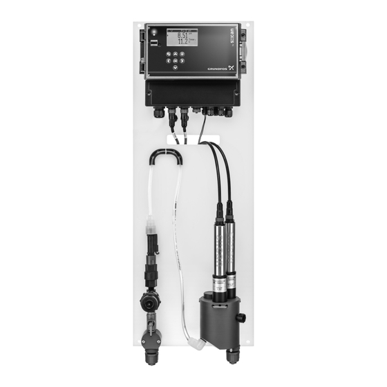
(drinking-, bathing-, waste-water, ...). The hydraulic part of the station manages the complete water flow from the inlet to the outlet of the DID. This includes filtration, pressure reduction, flow restriction and flow control as well as specific designed flow cells for proper mounting of the sensors and appropriate sampling. -
Page 7: Identification
7.4 Identification The following device variants of the DID are available. Regarding 7.4.2 Type key detailed information of the device variants please refer to the Example: DID-3 BF3-FCL2/TCL2/pH technical data located at the end of the manual: Code Description 7.4.1 Nameplate... - Page 8 7.4.3 Standard range DID pre-assembled system Hydraulic setup: Bypass flowcell with flow switch Product Purpose/applications Parameter 1 Parameter 2 Parameter 3 Description number Free Chlorine Free chlorine dosing control DID-1 BF1-FCL2 98915656 0-2 ppm Chlorine dioxide dosing control DID-1 BF1-CDI2...
-
Page 9: Control Functions
8. Control functions 8.1 Operating elements Fig. 6 Operating elements Fig. 7 Control unit CU 382 8.2 Functions overview Pos. Description Features CU 382-1 CU 382-3 Green power LED 1 plug for connection of digital s::can Orange communication LED ● sensors •... -
Page 10: Operating The Product
9. Operating the product 9.1 Software overview The CU 382 has four different views which can be selected by using [Right]- and [Left]-button. The default screen (i.e. after restart) is the Parameter screen. Pressing [Back] button several times (depends on level of sub menu) will always get the user back to one of these screens Status Parameter Controller... -
Page 11: General Set Up / Status
9.1.3 Controller screen 9.2 General set up / status Pressing [Function] button while the controller shows the status < ∧ C2/2 pH > screen will open up the Setup menu. 15 % ∨ Setup ► Manage sensors... Type: PID/Running Manage parameters.. >... - Page 12 Manage Sensor / Sensor / Sensor configuration After adding a sensor, a parameter has to be added. See section • Add parameters Sensor configuration 9.2.2 Manage parameters ► Configure... Manage parameters Add parameters... Remove ► Temp. • Configure The submenu Configure is only available for analog and digital inputs.
-
Page 13: Parameter / Settings
Day defines the day of date. To change the day, select Day 9.3 Parameter / settings with [Up]- and [Down] buttons and by pressing [OK] button the day can be changed with [Up]- and [Down] buttons. Pressing ∨ P1 FCL/mg/l [OK] button confirms the new day. - Page 14 Performing an offset calibration Performing a Span calibration ∨ P2 Calibration expert ∨ P1 Calibration expert ► Type: Local ► Type: Local Mode: Offset Mode: Span Perform. Calibration Perform. Calibration Value: 7.77 Value 0.50 Lab 1: Private: ∧ P1 Calibration expert ∧...
- Page 15 To change the lower level of alarm-trigger, select Al. lower with Within this line the measured value of the sensor [Up]- and [Down] buttons and by pressing [OK] button the lower Value: as displayed on the Parameter screen also (using level can be changed with [Up]-, [Down]-, [Left]- and [Right] the actual calibration).
- Page 16 [0 %] defines the parameter value for 0 %-output ∧ P2 Parameter info (0 pulses/min); ► Disp. Format: [100 %] defines the parameter value for 100 %- PULSE output (max. pulses/min). P. lower: 0.00 Pulses/min defines the maximum number of pulses P.
-
Page 17: Controllers / Settings
9.4 Controllers / settings To change the source for the external setpoint select Source with [Up]- and [Down] buttons and by pressing [OK] button the source can be changed with [Up]-, [Down]-, [Left]- and [Right] button. ∨ C2 pH/ Pressing [OK] button will confirm the source. ►... - Page 18 Max. 100 % [s] will define the maximum dosing time with a 9.4.3 Settings 2-P controller output of 100 %. The unit is [s]. ∨ C2 Settings To change the maximum dosing time select Max. 100 % [s] with [Up]- and [Down] buttons and by pressing [OK] button the ►...
- Page 19 If it is up the controller increase controller output if setpoint is In the submenu Stop on alarms… the behaviour of the controller above the parameter and decrease controller output if setpoint is for every parameter alarm can be defined. See section Stop on below the parameter.
-
Page 20: Alarms
9.5 Alarms 9.6.1 Result file The structure of the result file is defined as follows: < AP001 A1/1 Timestamp Seconds since 1970/1/1 2015/Oct/05 16:42:21 Flow below Time YearMonthDay-HourMinuteSecond lower alarm limit Marks the beginning of the parameter data block The header shows the amount of alarms and the number of the selected alarm. -
Page 21: Servicing The Product
As the line strainer removes larger sediment from the influent to check the DID. Regarding the functional check of the individual water stream, it is not expected that the flow detector will require sensors, please refer to the sensor manual. -
Page 22: Troubleshooting
• Air bubbles inside flow cell • Reduce pressure in inlet Readings are not within the • Sensor / DID was powered on recently • It may take up to an hour before a sensor provides correct specified and calibrated values •... -
Page 23: Technical Data
12. Technical data 12.1 Hydraulic specifications For variants BF1 and BF3 Data Units Number of connectable S::CAN sensors Min liquid temperature* °C General data Max liquid temperature* °C Min. ambient temperature* °C Max.ambient temperature* °C Min flow rate Max. flow rate (integrated limitation) Hydraulic data Max. - Page 24 Description Units D-320-GF1-230 D-320-GF3-230 Response time [ms] <1 <1 Drift over full temperature range +30 µA to +0 µA at 10mA +30 µA to +0 µA at 10mA Uncertainty [uA] <30 <30 Digital output / Relay output Description D-320-GF1-230 D-320-GF3-230 Number of NO relays Number of NO/NC relays (error relays)
- Page 25 Sensor Description D-320-GF1-230 D-320-GF3-230 1 x Buccaneer 400 Series 3 x Buccaneer 400 Series Connection 1 x Terminal block, stripped wire, AWG 28-12 1 x Terminal block, stripped wire, AWG 28-12 Intended use For use with s::can sensors For use with s::can sensors Maximum load 7 (constant), <15 (peak) 7 (constant), <15 (peak)
-
Page 26: Weights
12.4 Dimensions Within the figures below the needed dimensions for mounting the DID equipped with one sensor or up to three sensors are displayed. Furthermore the exact position of the water inlet and outlet are marked. Finally the dimensions of the Control unit CU 382 are displayed. - Page 27 Ø 50 Ø 60 Fig. 12 Dimension of control unit CU 382 for wall Fig. 13 Dimension of sensor with holder (mm), pipe with mounting, back (mm) external diameter 50 mm not included...
-
Page 28: Appendix
13. Appendix 13.1 Symbols on the product The most important notes to be considered during installation and operation of the DID are shown on the panel Label / Icon Description Label / Icon Description If a problem occurs call Grundfos Service Hotline. - Page 29 Declaration of Conformity relates, is in conformity with Directives, Standards and other Normative Documents as listed. Type of product: Measurement & Process Control Name of product: DID Model number: D-320-GF1-230, D-320-GF3-230 — Low Voltage Directive (2014/35/EU) Standard used: EN 61010-1:2010 —...
- Page 31 GRUNDFOS Pumps (Hong Kong) Ltd. Telefax: +64-9-415 3250 Turkey «Порт» Unit 1, Ground floor GRUNDFOS POMPA San. ve Tic. Ltd. Sti. Norway Тел.: +7 (375 17) 286 39 72/73 Siu Wai Industrial Centre Gebze Organize Sanayi Bölgesi Факс: +7 (375 17) 286 39 71 29-33 Wing Hong Street &...
- Page 32 99037650 0216 ECM: 1175263 www.grundfos.com...
Need help?
Do you have a question about the DID and is the answer not in the manual?
Questions and answers