Table of Contents
Advertisement
Quick Links
Advertisement
Table of Contents

Subscribe to Our Youtube Channel
Related Manuals for Leister axetris LGD Compact Series

Summary of Contents for Leister axetris LGD Compact Series
- Page 1 Operating & Integration Instructions Laser Gas Detection OEM Module LGD Compact...
- Page 2 For questions, service and maintenance information please contact: Europe and Asia Americas Headquarters Exclusive Distributor Axetris AG Leister Technologies LLC Company of the Leister Group 1275 Hamilton Parkway Schwarzenbergstrasse 10 Itasca IL 60143 6056 Kaegiswil Switzerland Toll-Free: +1 844 AXETRIS (844 293 8747)
- Page 3 Important safety instructions Warnung Vorsicht Das Gerät ist nur mit einem Druck von 800 – 1100 Gefahr! Das Gerät nicht öffnen. Laser Klasse 1. mbar zu betreiben. Das System darf nicht in einer explosiven Umgebung benutzt werden. Keine ATEX Zertifizierung. Hinweis Verbrennungsgefahr! Gasanschlüsse und Gehäuse nicht Reparaturen sind ausschliesslich durch eine...
- Page 4 Advertencia Precaución El equipo solo debe operarse con una presión de 800 Peligro No abrir el equipo. Láser clase 1. – 1100 mbar. No se debe utilizar el sistema en un ambiente potencialmente explosivo. Sin certificación ATEX. Indicación Peligro de quemaduras. No toque las conexiones de gas Solo los puntos de servicio técnico Axetris están ni la carcasa si están calientes.
- Page 5 警告 注意 センサーは800~1100 mbarの圧力でのみ動作しま 危険!デバイスを開けないでください。クラス1のレー ザー。 す。 システムは、爆発性のある環境で使用することはでき ません。ATEX認定はありません。 注記 ヤケドの危険があります!高温状態において、ガス接 認定されたAxetrisサービスセンターのみが修理を実 続部およびハウジングに触れないでください。熱風融 施することができます。 着機をクールダウンさせます。 有毒ガスの潜在的に危険な濃度を測定する場合、安全 取扱説明書で提供されているすべての情報および警 な場所においてセンサーを差し込む必要があります。 告情報に従う必要があります。 경고 주의 센서는 반드시 800 – 1100 mbar의 압력으로 위험! 장치를 개방하지 마십시오. 1 등급의 레이저. 가동해야 합니다. 본 시스템은 폭발 환경에서 사용하지 말아야 합니다. ATEX 인증...
- Page 6 About this Operating & Integration Instructions This Operating & Integration Instructions is the original and legally correct version. The aim of this Operating & Integration Instructions is to provide the user all the necessary information to install, operate and maintain LGD Compact Series Products. This Operating &...
- Page 7 CAUTION Product damage Read all instructions carefully before using the device. The LGD Compact gas sensor modules are not designed to sense liquid flow and damage will result if liquid is passed through the sensor. Gas loaded with particles will eventually contaminate the optics and affect the performance of the sensor.
-
Page 8: Table Of Contents
Index GENERAL USER INFORMATION ......................10 LGD Compact introduction ......................10 General Specifications ........................10 Environmental conditions ...................... 10 Mechanical characteristics ....................11 Electrical characteristics ......................11 Data interface ........................11 Measurement software / Customer Frontend ................12 SYSTEM SET-UP FOR EVALUATION ....................13 Operation conditions, storage &... - Page 9 Status, error and failure response ....................34 MAINTENANCE AND TROUBLE SHOOTING ..................35 Maintenance ..........................35 Troubleshooting ..........................36 IMPORTANT DISCLAIMER / NOTICE ....................37 FCC STATEMENT ..........................37 ANNEX ................................. 38 Status, Warning and Error Code Listing for Evaluation ................38 Status, Warning and Error Code Listing for Integrators/OEMs ..............
-
Page 10: General User Information
1 GENERAL USER INFORMATION 1.1 LGD Compact introduction Axetris’ laser gas detector (LGD), “LGD Compact”, is a system for the continuous monitoring of gases such as Tunable Diode Laser Spectrometry and CO . Based on state-of-the-art (TDLS), the system has a very high selectivity to the target gas and features an innovative, patented measurement principle without the need for a physical reference channel. -
Page 11: Mechanical Characteristics
Mechanical characteristics Parameter Unit Value / Range Measurement cell Flow-through set-up Cell volume Gas flow (min - max) ml / min 100 - 3’000 163 (length) Dimensions of sensor module 50 (diameter w/o fittings and electrical connector) ≤ 600 Approx. weight sensor module Dimensions of electronic unit 257 x 83 x 26 (L x W x H) with housing... -
Page 12: Measurement Software / Customer Frontend
Module powered at 3.7 – 5 VDC (without interface board) Parameter Unit Value / Range RS 232 TTL RS232 protocol, TTL signal amplitude 0 - 3.3 VDC Analog Voltage Output 0 - 2.5, 12-bit resolution Resistive loads kΩ > 5 Capacitive loads <... -
Page 13: System Set-Up For Evaluation
2 SYSTEM SET-UP FOR EVALUATION 2.1 Operation conditions, storage & transport The instrument must be used within the specified ambient conditions and temperature range. Depending on information provided by the customer, the factory calibration temperature range might cover a narrower range adapted to the application and reducing the complexity of the calibration. -
Page 14: Sensor Module
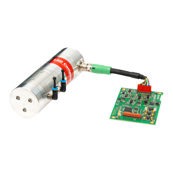
Sensor module The LGD Compact-A module has two M4 threaded mounting holes located on the side (see Figure 2, recommended to use two pan head cap screw M4x16 (1.5 Nm) for mounting). For gas supply there are straight/angled QSML-M5-4 quick connectors for 4 mm diameter tubes. Figure 2 LGD Compact-A module dimensions and interfaces for fixation and gas supply Electronics The electronics is located in a separate housing. -
Page 15: Electrical Interfaces
Figure 5 Dimensions of the interface board Figure 4 Dimensions of the main board The electronic main board should be connected to the sensor module just with the original cable delivered (recommendations for an own cable design can be seen in chapter 3.1.4). The right position for connecting the cable to the sensor module are marked on the cable connector as well as on the sensor module. -
Page 16: D-Sub Power Supply And Communication J1 (15Pol, 2 Rows)
Position the LGD Compact module at the location where the measurement will be carried out and where computer, power supplies and gas delivery systems can be installed. For customer support and system service it is ideal if the computer also can be connected to the internet. To allow simplified connectivity for evaluation a cable integrating both, system power supply and RS232, are provided (straight RS232 version, not crossed). -
Page 17: Micromatch Connector J3 (16Pol)
Table 1 Connector assignment 15pol D-Sub (2 rows) Name Description Power POWER IN Power supply input 10 …30V Supply GND IN* Power supply ground (has to be used separated from GND to ensure a proper power supply noise filtering) SHIELD D-Sub 15 Connector –... -
Page 18: Micromatch Connector J5 (20Pol)
Micromatch connector J5 (20pol) Figure 11 Connector assignment Micromatch 20pol Ordering number receptacle: Manufacturer: TE connectivity Description: MICRO-MATCH MOW.20P Article number: 9-215083-0 Be careful in case of connecting J5 directly because there is no protection circuit implemented on the main board! The protection circuit is placed on the interface board. -
Page 19: D-Sub Sensor Module J2 (15Pol, 3 Rows)
D-Sub sensor module J2 (15pol, 3 rows) The sensor module is connected to the electronic housing via a three row D-sub connector. Figure 12 shows the pin assignment. Figure 12 Sensor module connector assignment Table 4 Connector assignment 15pol D-Sub (3 rows) Name Description Measurement... -
Page 20: Micromatch Connector J6 (10Pol)
Micromatch connector J6 (10pol) Figure 13 Connector assignment Micromatch 10pol Ordering number receptacle: Manufacturer: TE connectivity Description: MICRO-MATCH MOW.10P Article number: 8-215083-0 Table 5 Connector assignment 10pol Micromatch Name Description Measurement PD_I Photodiode signal PD_GND* Laser control Laser_Drive Laser diode Laser_GND... -
Page 21: Gas Conditioning And Filtering Information
2.4 Gas conditioning and filtering information The LGD Compact Gas Sensor Modules are based on an optical measurement technique where performance is directly linked to optical transmission through the measurement cell. Sample gas containing particles and aerosols are likely to contaminate the optical windows of the measurement cell and degrade the optical transmission more or less quickly. -
Page 22: Zeroing And Purging
Adjustment of the sensor calibration "Concentration_Offset" [ppm] and "Concentration_Span" [ppm] allows correcting the measured values with the linear function: Offset Span meas In practice, the correction values are entered: e.g. if the measured offset is -1 ppm, 1 has to be entered under Customer offset, and if the slope for the span (or “gain”) is too steep by 5%, enter 0.95 under Customer Span to correct the slope. -
Page 23: Instructions For Lgd System Integration
3 INSTRUCTIONS FOR LGD SYSTEM INTEGRATION Please also check for relevant information in Chapter 2 regarding system setup for evaluation. 3.1 Integration options To facilitate the integration of the LGD Compact-A sensor module the electronics housing as well as the interface board can be removed and the module can be operated with the main board only. -
Page 24: Without Housing
Without housing Figure 17 Ground concept without housing Notes: The cable shield from the sensor module has to be connected to the earth potential. The six marked screws (see Figure 17) have to be connected to the same earth potential. Without housing and without interface board Figure 18 Ground concept without housing and without interface board Notes:... -
Page 25: Instructions For Cable Packaging
Instructions for cable packaging The LGD compact module will be delivered with an electrical cable from sensor housing to electronic boards (all available cable types can be seen in chapter 1.2.2) The EMC conformity tests were done with the cable packaging M12 straight D sub 200 mm shielded (Phoenix Contact 1430200). -
Page 26: Data Transmission Protocol
Figure 21 Pin connection for the Micromatch on LGD compact main board 3.2 Data transmission protocol The LGD module has multiple commands to communicate with other devices, like microcontrollers, or with the LGD Customer Frontend when it is connected to a PC. The following describes the structure of all commands necessary for the integration and use of the sensor. - Page 27 Command The data transfer is based on packets constituted of a multiple of 8 Bytes. The general structure for data transmission to the device is given in Table 7 and an example is given in Table 8. Command Table 7 General structure for data transmission to the device Byte Value...
-
Page 28: Timing & Rs232-Protocol
7B 50 58 00 00 00 05 03 0B 00 03 0C 00 05 16 00 05 17 00 05 18 00 00 00 00 00 00 00 80 3F 00 00 FA 43 00 00 7A 44 CD CC CC 3D 00 00 00 Response in Hex 00 00 00 00 00 17 B7 D1 38 00 00 00 00 00 00 00 00 00 00 00 00 00 00 80 7F 00 00 00 3F 00 00 80 7F 00 00 00 00 00 00 00 00... -
Page 29: Measurement Data Format
Very long commands > 64 bytes For very long commands (> 64 bytes) it’s important that the packet transmission lasts a certain amount of time. AXAG recommends adding a waiting time of 5 ms every 8 bytes during transmission, to lengthen the transmission time and avoid problems. -
Page 30: Change Of User Parameters
3.4 Change of user parameters To change the user parameters of the device, follow the procedure as given below: Idle Send (I) command Idle The device enters mode and then is able to access the user data in the RAM (see Chapter 3.5.2) Ping (P) user data Ping... -
Page 31: Stop Measurement (Idle)
Stop measurement (Idle) Idle Ping Send the -command to stop the current measurement. This allows accessing ( ) the user parameters. Command in Hex 7B 49 08 00 00 EA Command in ASCII { I ..Idle Idle As a confirmation, the device responds with an (without any data). -
Page 32: Configure User Data
71 – 74 00 00 00 00 Reserved variable for future use (dummy) 75 – 78 00 00 00 00 Trailing zeros 79 – 80 End of packet with checksum Please note that this general description may be subject to changes depending on single product execution. -
Page 33: Save To Eeprom
31 – 34 00 00 80 BF Analog output: Offset (here: -1) 35 – 38 0A D7 23 3C Analog output: Span (here 0.01) 39 – 42 00 00 20 41 Integration time (here: 10) 43 – 46 00 80 BB 44 Concentration gas 2 Offset (here 1500) 47 –... -
Page 34: Starting Measurements
Starting measurements Idle Measurement- If the device is in -mode and does not perform measurements, it can be re-started with the command. Command in Hex 7B 4D 08 00 01 EA Command in ASCII { M ..Measurement As a confirmation, the device responds with a -packet without any data. - Page 35 4 MAINTENANCE AND TROUBLE SHOOTING 4.1 Maintenance The Axetris LGD Compact gas sensor modules will not require routine maintenance when the installation and operation instructions described in this document are carefully applied. The surface of the instrument can be cleaned with a soft tissue and the use of isopropyl alcohol. Any gas filtration and conditioning equipment must be checked and replaced periodically according to manufacturer specifications.
- Page 36 4.2 Troubleshooting If you have problems while using the LGD Customer Frontend, please check if The device’ power supply is plugged-in and properly working The serial connection is set and data transmission is working The correct serial port is set on startup ...
- Page 37 5 IMPORTANT DISCLAIMER / NOTICE The information furnished by Axetris AG is believed to be correct and accurate. However, Axetris shall not be held liable to recipient of any third-party for any damages, including but not limited to personal injury, property damage, loss of profits, loss of use, interruption of business or indirect, special incidental or consequential damages, of any kind, in connection with or arising out of the furnishing, performance or use of technical data provided herein.
- Page 38 ANNEX A. Status, Warning and Error Code Listing for Evaluation MESSAGE IN GUI Action / Solution Detailed explanation 0x13 Unexpected Error (Watchdog) . Reboot Check communication. Check command structure and sensor connectivity. (15s) Contact service if problem persists 0xEF End of Life Soon, sensor will no longer work The sensor will soon be out of service.
- Page 39 B. Status, Warning and Error Code Listing for Integrators/OEMs MESSAGE IN GUI Action / Solution Detailed explanation 0x02 First byte of packet is not “{“ Check command structure. First byte of packet is not “{“ 0x04 Command ID is not a letter Check command structure.
- Page 40 C. Examples for Analog Output Adjustments See Chapter 2.5 for instructions. Example 1 [0 ppm = 4 mA or 0 V; 100 ppm = 20 mA or 5 V] delta Concentration [ppm] Analog voltage [V] Analog current [mA] Normalized (N ) [] ...
- Page 41 Example 3 [50 ppm = 8 mA or 1.25 V; 100 ppm = 16 mA or 3.75 V] delta Concentration [ppm] Analog voltage [V] 1.25 3.75 Analog current [mA] normalized [] 0.25 0.75 Span ...
- Page 42 D. Product Dimensions Figure 23: General view of the LGD Compact-A module (execution without electronics housing) Figure 24: Side and front view, with gas connectors. Dimensions in mm Axetris AG LGD Compact Operating & Integration Instructions; Rev. D 42/46...
- Page 43 Figure 25: View of the electronics housing. Dimensions in mm Figure 26: Main printed circuit board. Dimensions in mm Axetris AG LGD Compact Operating & Integration Instructions; Rev. D 43/46...
- Page 44 Figure 27: View of the interface printed circuit board. Dimensions in mm Axetris AG LGD Compact Operating & Integration Instructions; Rev. D 44/46...
- Page 45 Name of Authorized document official: Rui Protasio, Document Owner Disposal Electrical equipment, accessories and packaging should be recycled in an environment friendly way. When you are disposing of our products please observe the national and local regulations. For EU countries: Do not dispose of electrical equipment with household refuse. Axetris AG LGD Compact Operating &...
Need help?
Do you have a question about the axetris LGD Compact Series and is the answer not in the manual?
Questions and answers