Benning IT 130 Short Instructions
Installation tester
Hide thumbs
Also See for IT 130:
- Operating manual (87 pages) ,
- Short instructions (24 pages) ,
- Operating manual (140 pages)

Related Manuals for Benning IT 130


Summary of Contents for Benning IT 130
- Page 1 Installation Tester BENNING IT 130 Short instructions GB: Detailed instruction manual on enclosed CD-Rom.
- Page 2 BENNING IT 130 short instructions Benning Elektrotechnik & Elektronik GmbH & Co. KG Münsterstraße 135 - 137 D - 46397 Bocholt Phone: +49 (0) 2871 - 93 - 0 • Fax: +49 (0) 2871 - 93 - 429 www.benning.de • duspol@benning.de ©...
-
Page 3: Table Of Contents
Table of Contents BENNING IT 130 short instructions Start-up guide ........................... 4 Safety and operational considerations ..................4 Front and connector panel ....................... 6 Standard scope of delivery ...................... 7 Indications and meaning of symbols ..................8 Selecting measuring functions ....................9 Switch position „AUTO“... -
Page 4: Start-Up Guide
Service, repairs or adjustment of instruments and accessories is only allowed to be carried out by a competent authorized personnel! Please use standard or optional BENNING accessories only which are available from your authorized specialty retailer! Consider that protection category of some accessories is lower than of the instrument. - Page 5 BENNING IT 130 short instructions Warnings related to safety – measurements Insulation resistance Insulation resistance measurement should only be performed on de-energized objects! Do not touch the test object during the measurement or before it is fully discharged! Risk of...
-
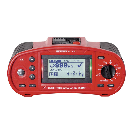
Page 6: Front And Connector Panel
1.2 Front and connector panel BENNING IT 130 short instructions Legend: 128 x 64 dots matrix display with backlight. Modifies selected parameter. DOWN TEST Starts measurements. Acts also as the PE touching electrode. Goes one level back. Selects the parameters in selected function. -
Page 7: Standard Scope Of Delivery
1 x RS 232-PS/2 interface cable (item no. 10008313) 1 x USB interface cable (item no. 10008312) 1 x charger (item no. 10008308) 1 x CD-ROM with BENNING PC-WIN IT 130 logging software, operating manual and quick reference guide in PDF format 1 x quick reference guide... -
Page 8: Indications And Meaning Of Symbols
1.4 Indications and meaning of symbols BENNING IT 130 short instructions Terminal voltage monitor The terminal voltage monitor displays on-line the voltages on the test terminals and information about active test terminals in the AC installation measuring mode. The voltage applied is displayed by means of the testing terminal symbol. All three testing terminals L, N and PE are used for the selected measurement. -
Page 9: Selecting Measuring Functions
Fuse F1, F2 or F3 is defective. If one of the fuses F2 or F3 has blown, the device must not be used anymore. In this case, the device must be sent to BENNING for inspection and repair. 1.5 Selecting measuring functions... -
Page 10: Switch Position „Auto
2/3 R ISO: >999 M no.: 3/3 R LOW: 0.17 The PC software BENNING PC-Win IT 130 (included in the delivery) serves to read the memory of measured values of the tester (download) and to transmit installation structures that have already been created on the PC to the tester (upload).... -
Page 11: Batteries And Fuses
If one of the fuses F2 or F3 has blown, the device must not be used anymore. In this case, the device must be sent to BENNING for inspection and repair. M 0,315 A / 250 V, 205 mm... -
Page 12: Calibration And Service
6 pieces Calibration Benning guarantees compliance with the technical and accuracy specifications stated in the operating manual for the first 12 months after the delivery date. To maintain accuracy of the measuring results, the device must be recalibrated in regular intervals by our factory service. -
Page 13: Optional Accessories
2 x L = 20 m, 1 x L = 4.5 m item no.: 044113 Current clamp adapter BENNING CC 1, 1 A - 400 A AC output: 1 mV per 1 A item no.: 044037 BENNING CC 3, 0.2 A - 300 A AC/DC output: 1 mV/10 mV per 1 A item no.:... -
Page 14: Measurements
Measurements 2.1 Null balance (compensation) of the test cables BENNING IT 130 short instructions 1. Set function Select R LOW or CONTINUITY. R LOW Short-circuit the test cables. Shorted test leads 3. Press the key 4. Press the key CAL (HELP). -
Page 15: Trms Voltage (V Ac/Dc), Frequency And Phase Sequence (Rotary Field)
2.2 TRMS voltage (V AC/DC), frequency and phase sequence (rotary field) BENNING IT 130 short instructions 1. Set function 2. Connection diagrams Connection of "Commander" test plug (optional) and 3-wire test lead in single-phase system Connection of the three-wire test cable and of the three-phase adapter (optional) in a three-phase system 3. -
Page 16: Insulation Resistance (R )
2.3 Insulation Resistance (R BENNING IT 130 short instructions 1. Set function 2. Set parameters and limits. Test voltage [50 V, 100 V, 250 V, 500 V, 1000 V] Minimum limiting value [without (---), 0.01 M ÷ 200 M] R ISO 3. -
Page 17: Low-Impedance Resistance (R )/ Continuity Test
Buzzer [ON/OFF] only for CONTINUITY R LOW function 3. Connection diagrams Connection of the three-wire test cable and of the optional measuring line BENNING TA 5 (044039) Connection of 3-wire test lead and "Commander" probe tip 4.b CONTINUITY: 4.a R LOW low impedance... -
Page 18: Residual Current Operated Device (Rcd)
2.5 Residual current operated device (RCD) BENNING IT 130 short instructions 1. Set function 2. Set sub-function, parameters and limits. RCD I Tripping current RCD t Tripping time Uc Contact voltage AUTO automatic test Nominal tripping differential current I [10/30/100/300/500/1000 mA]. -
Page 19: Loop Impedance (Z )
2.6 Loop impedance (Z BENNING IT 130 short instructions 1. Set function 2. Set sub-function, parameters and limits. Loop impedance: Zs (for systems without RCD) Zs rcd (for systems with RCD) Fuse type [---, gL/gG, gG, B, C, K, D]... -
Page 20: Line Impedance (Z )
2.7 Line impedance (Z BENNING IT 130 short instructions 1. Set function 2. Set sub-function, parameters and limits. Z Line Line impedance ΔU Voltage drop Fuse type [---, gL/gG , gG, B, C, K, D] Nominal current of the fuse... -
Page 21: Earth Resistance (R )
2.8 Earth resistance (R BENNING IT 130 short instructions 1. Set function 2. Set limits. EARTH RE Earth resistance Maximum limiting value [without, 1 Ω ÷ 5 kΩ] 3. Connection diagrams Connection of the optional earthing set (044113) 4. Press the key 5. -
Page 22: Current (A Ac/Dc)
Please set the current clamp adapter used under "SETTINGS". 2. Connection diagrams Connection of the optional current clamp adapter BENNING CC 1 (044037) , BENNING CC 3 (044038) 4. Press the key 5. The measuring result can be stored by means of the "MEM" key. -
Page 23: Luminous Intensity (Lux)
Minimum illumination [OFF, 0.1 lux ÷ 20 klux] 3. Connection diagrams Positioning of the luminous intensity sensor BENNING luxmeter type B (044111) 4. Press the key 5. The measuring result can be stored by means of the "MEM" key. E ..Luminous intensity... -
Page 24: First Fault Current (R ) In It Supply System (Isfl)
2.11 First fault current (R ) in IT supply system (ISFL) BENNING IT 130 short instructions 1. Set function 2. Set sub-function and limit. ISFL Single-fault leakage current (only in IT networks) Maximum limiting value [without, 3.0 mA ÷ 20.0 mA] 3.
Need help?
Do you have a question about the IT 130 and is the answer not in the manual?
Questions and answers