Table of Contents
Advertisement
Quick Links
Advertisement
Table of Contents

Related Manuals for Benning IT 120 B


Summarization of Contents
Safety and Operational Considerations
Warnings and Notes
General safety precautions, symbols, and warnings for instrument usage.
Battery and Charging Information
Details on battery types, replacement, charging, and precautions.
Applicable Standards
Lists regulations and European standards the instrument complies with.
Instrument Description
Front Panel Overview
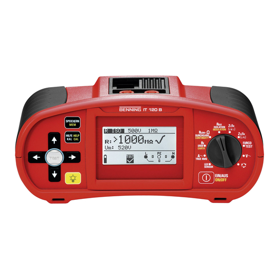
Description of the instrument's front panel controls and display elements.
Panel Views and Connections
Details on connector panel, back panel features, and bottom view components.
Instrument Carrying and Accessories
Guidance on carrying the instrument and details of standard and optional accessories.
Instrument Operation
Display Elements and Messages
Explains the display sections, symbols, and various warning/message indicators.
Setting Parameters and Help Menu
How to adjust measurement settings, parameters, limits, and access help.
Setup Menu Options
Configuration options including supply system, language, and communication settings.
Display Contrast Adjustment
Adjusting the display's backlight level and contrast for better visibility.
Measurements
Insulation Resistance
Procedures for measuring insulation resistance, including parameters and connections.
Resistance and Continuity Testing
Detailed steps for low resistance (RLOW) and continuity measurements.
RCD Testing Procedures
Covers contact voltage, trip-out time, trip-out current, and RCD autotest.
Loop Impedance and Short-Circuit Current
How to measure loop impedance (Zl, Zsrcd) and line impedance, and calculate prospective short-circuit current.
Phase Rotation, Voltage, Frequency, PE, Earth Resistance Tests
Testing phase rotation, measuring voltage/frequency, PE terminal, and earth resistance.
TRUE RMS Current and Illumination Measurements
Measuring AC currents and illumination levels.
Working with Measurement Results (BENNING IT 120 B only)
Saving Measurement Results
Step-by-step guide to storing measurement data in the instrument's memory.
Recalling and Deleting Results
How to retrieve, view, and delete previously saved measurement data.
RS232 and USB Communication (BENNING IT 120 B only)
PC Software for Data Transfer
Using PC software to document, protocol, and export measurement results from the instrument.
Maintenance
Fuse Replacement, Cleaning, and Calibration
Instructions for fuse replacement, cleaning, and the importance of periodic calibration.
Service and Contact Information
Information on contacting the manufacturer for service, repairs, and warranty.
Technical Specifications
Insulation, Resistance, Continuity Specs
Technical details for insulation resistance and resistance/continuity measurements.
RCD, Impedance, Line Impedance Specs
Detailed specifications for RCD, loop impedance, and line impedance tests.
Voltage, Frequency, PE, Earth Resistance, TRUE RMS, Illumination Specs
Specifications for voltage, frequency, PE terminal, earth resistance, TRUE RMS current, and illumination.
General Data Specifications
General specifications including power, dimensions, weight, and operating conditions.
Appendix A: Fuse Base Tables
Fuse Base Tables
Comprehensive tables of fuse types, clearing times, rated currents, and prospective short-circuit currents.
Appendix B: IT Systems
IT System Standards, Information, and Guidelines
Applicable standards, basic information, and measuring guidelines for IT power supply systems.
First Fault Leakage Current (ISFL) in IT Systems
Procedure for measuring the maximum current during a first fault in IT systems.
Appendix C: Lower Voltage Power Supply Networks
Lower Voltage Network Standards, Information, and Guidelines
Applicable standards, basic information, and measuring guidelines for lower voltage networks.
Lower Voltage Network Measurement Specifics
Details on voltage, RCD, loop resistance, and line resistance measurements for lower voltage networks.
Need help?
Do you have a question about the IT 120 B and is the answer not in the manual?
Questions and answers