Chapters
Table of Contents

Related Manuals for Benning PV 2


Summary of Contents for Benning PV 2
- Page 1 Bedienungsanleitung Operating manual PV 2 NULL Auto Mode Auto Mode a Vo/c, Is/c, MΩ b Vmpp, Impp, FF c a + b NULL 500V 250V 1000V DIN EN 62446 (VDE 0126-23), DIN EN 61829 (VDE 0126-24)
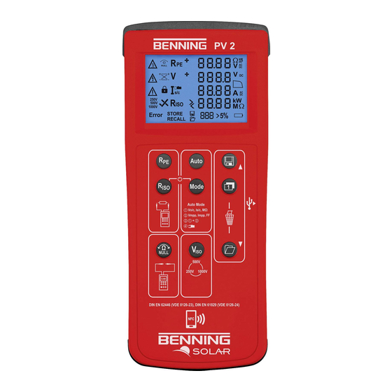
- Page 2 Appliance front face Fig. 1: Front tester panel CAT I CAT III 1000 V 300 V 10 A Bild 2: Geräteoberseite Fig. 2: Top side of the device Fig. 2: Top side of the device BENNING PV 2 12/ 2017...
- Page 3 DIN EN 62446 (VDE 0126-23), DIN EN 61829 (VDE 0126-24) Auto DIN EN 62446 (VDE 0126-23), DIN EN 61829 (VDE 0126-24) Mode Auto Mode a Vo/c, Is/c, MΩ b Vmpp, Impp, FF c a + b NULL 500V BENNING PV 2 12/ 2017 250V 1000V...
- Page 4 + b Auto NULL 500V 250V 1000V DIN EN 62446 (VDE 0126-23), DIN EN 61829 (VDE 0126-24) Mode Auto Mode a Vo/c, Is/c, MΩ b Vmpp, Impp, FF c a + b NULL 500V BENNING PV 2 12/ 2017 250V 1000V...
- Page 5 Vmpp, Impp, FF c a + b NULL Bild 8: AC/ DC-Strommessung mit optionalem 500V Stromzangenadapter BENNING CC 3 Fig. 8: AC/ DC current measurement by means 250V 1000V of optional current clamp adapter PV 2 BENNING CC 3...
- Page 6 DIN EN 62446 (VDE 0126-23), DIN EN 61829 (VDE 0126-24) PV 2 Auto Mode Auto Mode a Vo/c, Is/c, MΩ b Vmpp, Impp, FF c a + b NULL 500V 250V 1000V DIN EN 62446 (VDE 0126-23), DIN EN 61829 (VDE 0126-24) BENNING PV 2 12/ 2017...
- Page 7 D Bild 11: Funkverbindung zum optionalen Einstrahlungs- und Temperaturmessgerät BENNING SUN 2 Fig. 11: Radio connection to the optional insolation and temperature measuring instrument BENNING SUN 2 PV-Modul/ -Strang PV-module/ -string Max. P ≤ 10 kW Vo/c ≤ 1000 V Is/c ≤...
-
Page 8: Table Of Contents
Prüfung des Batteriezustandes 8.1.5 Kompensation der Sicherheitsmessleitungen (Nullabgleich) 8.2 Prüfung des Schutzleiterwiderstandes, RPE 8.3 Automatische Messungen am PV-Generator 8.4 Gleich- und Wechselspannungsmessung 8.5 Strommessung mit optionalem AC/ DC-Stromzangenadapter BENNING CC 3 8.6 Isolationswiderstandsmessung (RISO, 2-polig) 8.7 Messwertspeicher 8.7.1 Messwerte speichern 8.7.2 Messwerte aufrufen 8.7.3... -
Page 9: Sicherheitshinweise
Internationale, nationale und gegebenenfalls regionale Vorschriften der Elektrotechnik sind in jedem Fall einzuhalten. Einschlägige Kenntnisse der Elektrotechnik werden vorausgesetzt. Das BENNING PV 2 ist zur Messung in trockener Umgebung vorgesehen (näheres hierzu im Abschnitt 6: Umgebungsbedingungen). In der Bedienungsanleitung und auf dem BENNING PV 2 werden folgende Symbole ver wendet: Warnung vor elektrischer Gefahr! Steht vor Hinweisen, die beachtet werden müssen, um Gefahren für Menschen zu... -
Page 10: Lieferumfang
Über die 4 mm Sicherheitsmessleitungen sind Spannungsmessungen an Steckdosenstromkreise möglich. Das BENNING PV 2 darf über die 4 mm Prüf- buchsen O und P nur in Stromkreisen der Überspannungskategorie III mit max. 300 V AC/DC Leiter gegen Erde benutzt werden. Bei Spannungsmessun- gen über die 4 mm Prüf buchsen O und P sind vorher die PV-Sicherheitsmess-... -
Page 11: Gerätebeschreibung
Ein Stück Sicherung Nennstrom 500 mA, F, 1000 V, Trennvermögen ≥ 1000 A, D = 6,3 mm, L = 32 mm (T.Nr. 749771) Das BENNING PV 2 benötigt sechs 1,5 V Mignon-Batterien/ Typ AA, IEC LR6 Hinweis auf optionales Zubehör: PC-Software BENNING SOLAR Manager zur Prüfberichtserstellung und Dokumentation... -
Page 12: Allgemeine Angaben
Bei Arbeitstemperatur von 31 °C bis 40 °C: relative Luftfeuchte kleiner 75 %, Lagerungstemperatur: Das BENNING PV 2 kann bei Temperaturen von - 25 °C bis + 65 °C (Luft- feuchte 0 bis 90 %) gelagert werden. Dabei sind die Batterien aus dem Gerät herauszunehmen. -
Page 13: Prüfen Mit Dem Benning Pv
± (5 % + 2 Digit) Prüfen mit dem BENNING PV 2 8.1 Vorbereiten der Prüfung Benutzen und lagern Sie das BENNING PV 2 nur bei den angegebenen Lager- und Arbeits- temperaturbedingungen, vermeiden Sie dauernde Sonneneinstrahlung. Angaben von Nennspannung und Nennstrom auf den Sicherheitsmessleitungen überprüfen. -
Page 14: Einstellen Der Automatischen Abschaltzeit (Apo, Auto-Power Off)
Befindet sich das BENNING PV 2 in Funkverbindung mit dem BENNING SUN 2, synchro- nisiert sich das Datum/ die Uhrzeit des BENNING PV 2 automatisch nach ca. 10 s auf das Datum/ die Uhrzeit des BENNING SUN 2, wenn eine Abweichung > 1 Min. festgestellt wird. -
Page 15: Automatische Messungen Am Pv-Generator
> 1000 V liegt, ist keine automatische PV-Messung möglich. Zur Messung einer I-U Kennlinie (Prüfablauf/ Mode b + c ) müssen Sie zuerst das BENNING PV 2 mit dem Einstrahlungs- und Temperaturmessgerät BENNING SUN 2 koppeln (siehe Abschnitt 8.8 Funkverbindung zu BENNING SUN 2). - Page 16 - I-U Kennlinie (Vmpp, Impp, FF) Isolationswiderstand Mode d : „Stromzangensymbol“ im LCD-Display Messung von … - AC/ DC Betriebsstrom über BENNING CC 3 Drücken Sie die -Taste 3 um den ausgewählten Prüfablauf (Mode) zu starten. Auto Falls eine I-U Kennlinienmessung (Mode b + c ) ausgewählt wurde, erscheint während...
-
Page 17: Gleich- Und Wechselspannungsmessung
Spannungsmessung über 4 mm Prüfbuchsen 8.5 Strommessung mit optionalem AC/ DC-Stromzangenadapter BENNING CC 3 (T.Nr. 044038) Das BENNING PV 2 kann mit dem optionalen AC/ DC-Stromzangenadapter BENNING CC 3 den Betriebsstrom einer PV-Anlage messen. Die ermittelten Stromwerte können in dem internen Speicher des BENNING PV 2 abgelegt und wieder aufgerufen werden. -
Page 18: Messwertspeicher
8.7 Messwertspeicher 8.7.1 Messwerte speichern Das BENNING PV 2 kann bis zu 999 Displayanzeigen oder I-U Kennlinien speichern. Abhän- gig der durchgeführten Messungen werden pro Speicherplatz der Schutzleiterwiderstand, die Leerlaufspannung, der Kurzschlussstrom, der Isolationswiderstand mit Prüfspannung, die I-U Kennlinie (Umpp, Impp, FF) oder auch der gemessene AC/ DC-Strom (BENNING CC 3) mit einem Datum-/ Zeitstempel gespeichert. -
Page 19: Darstellung Der I-U Kennlinie Über Android-Gerät
Anleitung. Zur Anzeige der I-U Kennlinie starten Sie bitte die APP „BENNING PV Link“, die Sie kostenlos über den Google Play Store beziehen können. Um sich mit der APP „BENNING PV Link“ vertraut zu machen, lesen Sie bitte zuerst die in der APP integrierte Bedienungsanleitung, die Sie unter den Einstellungen/Hilfe finden. -
Page 20: Instandhaltung
-Taste angezeigt. Befindet sich das BENNING PV 2 in Funkreichweite des BENNING SUN 2, wird der Messwert der solaren Einstrahlung (W/m²) im LCD-Display 1 des BENNING PV 2 angezeigt. Eine AUTO-Messung (Mode 1, 2 und 3) des BENNING PV 2 erfasst zusätzlich die solare Einstrahlung, die Modul- und Umgebungstemperatur und den Datum-/ Zeitstempel des BENNING SUN 2. -
Page 21: Sicherstellen Des Gerätes
So wechseln Sie die Batterien (siehe Bild 12): Schalten Sie das BENNING PV 2 aus. Legen Sie das BENNING PV 2 auf die Frontseite und lösen Sie die Schraube vom Batteriedeckel. Heben Sie den Batteriedeckel (im Bereich der Gehäusevertiefungen) vom Unterteil ab. -
Page 22: Ersatzteile
Batterie-/ Sicherungswechsel Hinweis: Die PV-Prüfbuchsen M und N des BENNING PV 2 sind durch eine 15 A / 1000 V Solar-Siche- rung geschützt. Diese Sicherung ist nicht durch den Anwender austauschbar. Wenn die Solar- Sicherung durch Überlastung zerstört wird, zeigt das BENNING PV 2 einen Fehlercode an. Das BENNING PV 2 ist dann an den BENNING-Service einzusenden. - Page 23 8.2 Testing the protective conductor resistance (RPE) 8.3 Automatic measurements on the PV generator 8.4 AC/ DC voltage measurement 8.5 Current measurement by means of optional AC/ DC current clamp adapter BENNING CC 3 8.6 Insulating resistance measurement RISO (2-pin) 8.7 Measured value memory 8.7.1...
-
Page 24: Safety Note
Always observe international, national and - if applicable - regional regulations of electrical engi- neering. Relevant skills of electrical engineering are absolutely required. The BENNING PV 2 is intended for making measurements in dry environment (More details in chapter 6. “Environmental conditions”). -
Page 25: Scope Of Delivery
Via the 4 mm safety test leads, voltage measurements on mains supply circuits are possible. Via the 4 mm test sockets O and P , the BENNING PV 2 must be used only in electric circuits of overvoltage category III with max. 300 V AC/ DC for phase-to-earth measurements. -
Page 26: Unit Description
050425). AC/ DC current clamp adapter BENNING CC 3 for connection to the BENNING PV 2. The measured AC/ DC current values can be stored in the memory of the BENNING PV 2 and can be recalled (P.no. 044038). 40 m measuring leads BENNING TA 5 with practical rewinder and supporting loop. Connec- tion: 4 mm safety test socket/ plug (P.no. -
Page 27: General Information
23 (DIN EN 62446) and for measuring the current-voltage characteristic in compliance with VDE 0126-24 (DIN EN 61829). The BENNING PV 2 is not intended for continuous use. The BENNING PV 2 use is limited in use by delays in the firmware and also has temperature measuring circuits. If the internal tem- perature reaches the set limits then functionality will be reduced in order to allow the BENNING PV 2 to cool down. -
Page 28: Switching The Benning Pv 2 On/ Off
Measuring with the BENNING PV 2 8.1 Preparation for measuring Operate and store the BENNING PV 2 only at the specified storage and operating tempera tures conditions. Do not permanently expose the device to sunlight. Check rated voltage and rated current details specified on the safety measuring leads. -
Page 29: Setting The Date And The Time
Note: If the BENNING PV 2 has established a radio connection to the BENNING SUN 2, the date/ time of the BENNING PV 2 will be synchronized automatically after 10 seconds to the date/ time of the BENNING SUN 2, if the device detects a deviation of more than 1 minute. BENNING SUN 2 (master) →... -
Page 30: Automatic Measurements On The Pv Generator
BENNING PV 2 with the insolation and temperature measuring instrument BENNING SUN 2 (see section 8.8 “Radio connection to the BENNING SUN 2). Connect the BENNING PV 2 to the PV module or the PV string by means of the enclosed PV safety measuring leads. - Page 31 - I-V characteristic (Vmpp, Impp, FF) (insulating resistance) Mode d : “Current clamp symbol” on the LC display Measurement of... - AC/DC operating current via BENNING CC 3 Press the -key 3 to start the selected test procedure (mode). Auto...
-
Page 32: Ac/ Dc Voltage Measurement
8.5 Current measurement by means of optional AC/ DC current clamp adapter BENNING CC 3 (part no. 044038) By means of the optional AC/ DC current clamp adapter BENNING CC 3, the BENNING PV 2 can be used to measure the operating current of a PV system. The determined current values can be stored in the internal memory of the BENNING PV 2 and can be recalled. -
Page 33: Measured Value Memory
Umpp, I = Impp, FF = filling factor). When the “NFC” symbol N is shown on the LC display 1 , the I-V characteristic is written from the memory to the NFC chip of the BENNING PV 2. The characteristic can be viewed with an NFC-enabled Android device using the “BEN- NING PV Link”... -
Page 34: Radio Connection To Insolation / Temperature Measuring Instrument Benning Sun
As soon as the “NFC” icon N disappears, hold the NFC antenna of your Android device as close and still as possible over the NFC logo 8 on the top of the BENNING PV 2 housing. The I-V characteristic will be transferred to the Android device and displayed. -
Page 35: Maintenance
Before opening the BENNING PV 2, make quite sure that it is voltage free! Electrical danger! Work on the opened BENNING PV 2 under voltage may be carried out only by skilled electricians with special precautions for the prevention of accidents. -
Page 36: Securing The Instrument
BENNING PV 2. Danger of electric shock! The 4 mm test sockets P and O of BENNING PV 2 are protected against overload by means of one built-in fuse (500 mA, 1000 V, F, D = 6.3 mm, L = 32 mm) (P.no.749771). -
Page 37: Calibration
Note: The PV test sockets M and N of BENNING PV 2 panel shorting circuitry are protected by a 15 A, 1000 V Solar fuse. This fuse is not operator replicable. If this fuse blows then the BENNING PV 2 will indicate an error before the panel is shorted, the BENNING PV 2 must be returned for service. - Page 38 Benning Elektrotechnik & Elektronik GmbH & Co. KG Münsterstraße 135 - 137 D - 46397 Bocholt Phone: +49 (0) 2871 - 93 - 0 • Fax: +49 (0) 2871 - 93 - 429 www.benning.de • E-Mail: duspol@benning.de...
Need help?
Do you have a question about the PV 2 and is the answer not in the manual?
Questions and answers