Benning IT 130 Operating Manual
Installation tester
Hide thumbs
Also See for IT 130:
- Short instructions (24 pages) ,
- Short instructions (24 pages) ,
- Operating manual (140 pages)
Table of Contents
Advertisement
Quick Links
Advertisement
Table of Contents

Related Manuals for Benning IT 130


Summary of Contents for Benning IT 130
- Page 1 Installation Tester BENNING IT 130 Operating Manual...
- Page 2 Manufacturer: BENNING Elektrotechnik und Elektronik GmbH & Co. KG Münsterstraße 135 - 137 D - 46397 Bocholt Phone: +49 (0) 2871 - 93 - 0 • Fax: +49 (0) 2871 - 93 - 429 www.benning.de • duspol@benning.de This symbol on your device ensures that the device complies with the requirements laid down by the EU (European Union) with regard to safety and electromagnetic compatibility of devices.
-
Page 3: Table Of Contents
Attachment of the carrying strap ................18 Scope of delivery and optional accessories...............19 3.5.1 Standard scope of delivery ................19 3.5.2 Optional accessories ..................20 Operating the BENNING IT 130 installation tester ............21 Indications and acoustic warning signals..............21 4.1.1 Connection monitor ...................21 4.1.2 Battery indication ....................21 4.1.3... - Page 4 BENNING IT 130 Content Loop impedance and prospective short-circuit current..........46 Line impedance and prospective short-circuit current / voltage drop....48 5.6.1 Line impedance and prospective short-circuit current ........49 5.6.2 Voltage drop ......................50 Earthing resistance ....................52 Testing the protective conductor connection (PE) .............54 TRMS current by means of current clamp adapter ............56...
- Page 5 BENNING IT 130 Content Appendix A Fuse table – Prospective short-circuit current ..........81 Appendix B Standard and optional accessories for specific measuring functions ..84 Appendix C "Commander" test probe, "Commander" test plug........85 Safety warnings ....................85 Batteries........................85 Description of the "Commanders".................86 LED indications of the "Commanders"..............87...
-
Page 6: Preface
BENNING would like to congratulate you on purchasing this BENNING IT 130 installation tester and its accessories. The BENNING IT 130 installation tester is a multifunctional tester for testing electrical installations in compliance with IEC 60364-6 (DIN VDE 0100-600) and EN 50110 (DIN VDE 0105-100). -
Page 7: Safety And Operating Instructions
Warnings In order to ensure a high degree of operational safety during the tests and measurements and to avoid damaging of the BENNING IT 130 installation tester, the general warnings listed in the following must be adhered to. Warnings – general information:... - Page 8 BENNING IT 130 Safety and operating instructions Please observe that the measuring category of some accessories might be lower than that of the installation tester. Test probes and "Commander" test probes are provided with detachable protective caps. If these attachable protective caps are removed, the measuring category will be reduced to CAT II.
- Page 9 BENNING IT 130 Safety and operating instructions Remarks with regard to measurements: General icon means that the selected measurement cannot be carried out due to irregular conditions at the input terminals. Carry out measurements of the insulating resistance, low-impedance resistance, continuity and earthing resistance on discharged objects only! The "PASS"...
- Page 10 BENNING IT 130 Safety and operating instructions Loop impedance The lower limiting value of the prospective short-circuit current depends on the fuse type, on the fuse current rating and tripping time as well as on the I scaling factor. The stated accuracy of the parameters tested shall only apply, if the mains voltage is stable during measurement.
-
Page 11: Batteries / Storage Batteries And Charger
BENNING IT 130 Safety and operating instructions Batteries / storage batteries and charger The installation tester can be operated with six alkaline batteries (type AA) or with rechargeable NiMH batteries (storage batteries). The specified operating time refers to storage batteries with a nominal capacity of 2100mAh. - Page 12 BENNING IT 130 Safety and operating instructions Unpredictable chemical processes might occur during the charging of storage batteries that have not been used for a longer period of time (more than 6 months). In this case, it is recommended to repeat the charging / discharging cycle at least 2 to 4 times.
-
Page 13: Standards Applied
BENNING IT 130 Safety and operating instructions Standards applied The BENNING IT 130 installation tester is manufactured and tested in compliance with the following regulations: Electromagnetic compatibility (EMC) EN 61326-1 Electrical equipment for measurement, control and laboratory use – EMC requirements... -
Page 14: Device Description
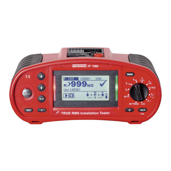
BENNING IT 130 Device description 3 Device description Front panel Figure 3.1: Front panel Caption: Matrix display with 128 x 64 pixels and background lighting Modifies selected parameters DOWN Start of measurement TEST PE contact electrode for protective conductor connection... -
Page 15: Connection Panel
USB interface (1.1) for PC connection Protective cover Measuring input for optional current clamp adapter BENNING CC 1 / BENNING CC 2 / BENNING CC 3 Serial RS232 interface for PC connection; PS/2 port connection for optional BENNING luxmeter type B (044111) and... -
Page 16: Rear Panel
BENNING IT 130 Device description Rear panel Figure 3.3: Rear panel Caption: Cover of the battery / fuse compartment Information label Screws for the battery / fuse compartment cover Figure 3.4: Battery / fuse compartment Caption: Fuse F1 M 315 mA / 250 V... -
Page 17: Carrying The Installation Tester
BENNING IT 130 Device description Figure 3.5: Bottom view Caption: Information label Carrying strap openings Lateral covers Carrying the installation tester The installation tester can be carried in different ways by means of the accessories included in the standard scope of delivery. -
Page 18: Attachment Of The Carrying Strap
BENNING IT 130 Device description 3.4.1 Attachment of the carrying strap Please choose one of the two methods shown: Figure 3.6: First method Figure 3.7: Alternative method Please check the carrying strap for safe fastening regularly. - 18 -... -
Page 19: Scope Of Delivery And Optional Accessories
6 x rechargeable NiMH storage batteries of size AA 2 x batteries of size AAA 1 x charger 1 x CD-ROM with BENNING PC-WIN IT 130 logging software, operating manual and quick reference guide in PDF format 1 x quick reference guide... -
Page 20: Optional Accessories
BENNING CC 2, 0.5 A to 20 A AC Output: 1 mA per 1 A Item no.: 044110 BENNING CC 3, 0.2 A to 300 A AC / DC Output: 1 mV / 10 mV per 1 A Item no.: 044038... -
Page 21: Operating The Benning It 130 Installation Tester
BENNING IT 130 Measurements 4 Operating the BENNING IT 130 installation tester Indications and acoustic warning signals 4.1.1 Connection monitor The connection monitor shows the voltages applied to the testing terminals as well as information on active testing terminals in the AC mains. -
Page 22: Evaluation Field
BENNING IT 130 Measurements A high interference voltage has been detected during measurement. This might result in incorrect measuring results. L and N have been interchanged. RCD has been tripped during measurement (in RCD functions). Portable RCD (PRCD) has been selected (only for documentation purposes). -
Page 23: Help Menu ("Help" Key)
BENNING IT 130 Measurements 4.1.6 Help menu ("HELP" key) HELP Opens the help menu. Help menus are available for all measuring functions. The help menu contains graphic connection diagrams showing how to connect the installation tester to the electrical installation. -
Page 24: Function Selector Switch
BENNING IT 130 Measurements Function selector switch The function selector switch is intended for selecting the test and measuring functions "AUTO" mode "SETTINGS" mode Key functions after having selected the test / measuring function: Selects the sub-function of the adjusted test / measuring function... -
Page 25: Settings" Mode
Figure 4.3: INITIAL SETTINGS (reset to factory settings) "SETTINGS" mode CLAMP settings (selection of the optional current clamp adapters BENNING CC 1 (044037), BENNING CC 2 (044110), BENNING CC 3 (044038)) Keys used: UP / DOWN Selects the respective option... -
Page 26: Date And Time
BENNING IT 130 Measurements Keys used: UP / DOWN Selects the language TEST Confirms the selected language and returns to the Settings menu Back / cancel to the Settings menu Function selector switch Back / cancel to the selected measuring function 4.4.3 Date and time... -
Page 27: Rcd Testing
BENNING IT 130 Measurements 4.4.5 RCD testing In this menu, it is possible to set the standard used for RCD testing. Figure 4.8: Selecting the RCD standard Keys used: UP / DOWN Selects the standard TEST Confirms the selected standard and returns to the Settings menu... -
Page 28: Isc Factor (Scaling Factor)
BENNING IT 130 Measurements Tripping times in compliance with AS/NZS 3017 ½×I 2×I 5×I ∆N ∆ ∆N ∆N RCD type I Remark [mA] ∆N ∆ ∆ ∆ ∆ 40 ms 40 ms 40 ms ≤ 10 > 999 ms 300 ms 150 ms 40 ms >... -
Page 29: Commander On/Off
BENNING IT 130 Measurements 4.4.7 Commander ON/OFF In this menu, it is possible to enable or disable the "Commander" (switchable test probe). Figure 4.10: Selecting the "Commander" support Keys used: UP / DOWN Selects Commander ON (enabled) / Commander OFF (disabled) -
Page 30: Clamp Settings
BENNING IT 130 Measurements Measuring function Parameter / limiting value Sub-function No limiting value R ISO without limiting value, nominal testing voltage: 500 V R LOW No limiting value CONTINUITY No limiting value ZI (L-N/L) line impedance Fuse type: none selected ∆U voltage drop... - Page 31 BENNING IT 130 Measurements Modifying the selected parameters Keys used: UP / DOWN Modifies the selected parameter TEST Confirms the selected parameter Saves the settings Back / cancel to the Settings menu Function selector switch Back / cancel to the selected measuring function Note: Please pay attention to the measuring range of the installation tester.
-
Page 32: Measurements
BENNING IT 130 Measurements 5 Measurements TRMS voltage, frequency and phase sequence The voltages applied to the testing terminals are permanently displayed by means of the connection monitor. In the VOLTAGE TRMS measuring range (true RMS voltage value), the measured values for voltage (AC/DC) and frequency as well as the phase sequence (rotary field) detected can be saved. - Page 33 BENNING IT 130 Measurements How to perform voltage measurements Select the function by means of the function selector switch. The display shows V≅ ≅ ≅ ≅ VOLTAGE TRMS. Connect the test cables to the test object (see figure 5.2 and figure 5.3).
-
Page 34: Insulating Resistance
BENNING IT 130 Measurements Insulating resistance The measurement of the insulating resistance is performed in order to prove the proper condition of the insulation and in order to exclude electrical danger. Typical applications are the following cases: Insulating resistance between the active conductors (L/N) of an installation and the protective conductor / earth (PE) =>... - Page 35 The warning symbol and the actual voltage will be displayed during discharging. Do not connect the test cables to external voltages higher than 550 V (AC or DC) in order not to damage the BENNING IT 130 installation tester! - 35 -...
-
Page 36: Low-Impedance Resistance / Continuity Test
5.3.1 Low-impedance resistance with a testing current of 200 mA The resistance measurement is performed with automatic polarity reversal of the testing voltage. Connection plan Figure 5.9: Connection of the three-wire test cable and the optional 40 m measuring line BENNING TA 5 (044039) - 36 -... -
Page 37: Continuity Test With A Testing Current Of 7 Ma
BENNING IT 130 Measurements How to perform low-impedance measurements R LOW Select the function by means of the function selector switch. Set the sub-function to R LOW Set the limiting value (optional). Connect the test cables to the installation tester and compensate the test cable resistance, if necessary (see section 5.3.3 Compensation (null balance) of the test cable... -
Page 38: Compensation (Null Balance) Of The Test Cable Resistance
BENNING IT 130 Measurements How to perform continuity tests Select the function by means of the function selector switch. Set the sub-function to CONTINUITY. Set the limiting value (optional). Connect the test cables to the installation tester and compensate the test cable resistance, if necessary (see section 5.3.3 Compensation (null balance) of the test cable resistance). - Page 39 BENNING IT 130 Measurements Note: The highest value for test cable compensation is 5 Ω. If the resistance is higher, the compensation value will be reset to the default value. icon is displayed, if the test cable resistance has not been compensated.
-
Page 40: Rcd Testing
BENNING IT 130 Measurements RCD testing The testing of RCDs in RCD-protected installations requires various tests and measurements. The measurements are based on the EN 61557-6 standard. The following measurements and tests can be performed: Contact voltage, tripping time, tripping current and... -
Page 41: Contact Voltage (Uc)
BENNING IT 130 Measurements Connection plan Figure 5.17: Connection of the optional "Commander" test plug (044149) and the three-wire test cable 5.4.1 Contact voltage (Uc) Leakage current flowing to earth via the protective conductor connection causes a voltage drop at the earthing resistance, i.e. a voltage difference between the PE equipotential bonding and earth. -
Page 42: Tripping Time (Rcdt)
BENNING IT 130 Measurements The loop resistance is a purely indicative value and is calculated from the contact voltage (without additional proportional factors). ∆ Figure 5.18: Example of a contact voltage measurement Results displayed: Uc ..contact voltage RL ..loop resistance (fault loop resistance) 5.4.2 Tripping time (RCDt) -
Page 43: Automatic Test
BENNING IT 130 Measurements Norm EN 61008/EN 61009, (SETTINGS mode → RCD TESTING): Increasing fault current Curve RCD type shape Initial value Final value sinusoidal 0,2×I 1,1×I ∆N ∆N A, F (I ≥ ≥ ≥ ≥ 30 mA) 0,2×I 1,5×I ∆... - Page 44 BENNING IT 130 Measurements How to perform an automatic test Steps of the automatic test Note Select the FI/RCD function by means of the function selector switch. Set the sub-function to AUTO. Set the testing parameters. Connect the test cables to the test object (see figure 5.17).
- Page 45 BENNING IT 130 Measurements Bottom Figure 5.22: The "HELP" key toggles between the upper and the lower part of the result field. Results displayed: x1 ..step 1 tripping time (I , 0º) ∆ ∆N x1 ..step 2 tripping time (I , 180º)
-
Page 46: Loop Impedance And Prospective Short-Circuit Current
BENNING IT 130 Measurements Loop impedance and prospective short-circuit current The loop impedance is a complex AC current resistance within a fault loop (earth fault L-PE) consisting of current source, external conductor and protective conductor. The installation tester measures the impedance of the loop and calculates the short-circuit current. The measurement complies with the requirements specified in the EN 61557-3 standard. - Page 47 BENNING IT 130 Measurements How to perform loop impedance measurements Select the (L-PE) [English: Z (L-PE)] function by means of the function selector LOOP switch. Set the sub-function to Zloop Zsrcd (for systems with RCDs). Set the testing parameters. Connect the test cables to the test object (see figure 5.24).
-
Page 48: Line Impedance And Prospective Short-Circuit Current / Voltage Drop
BENNING IT 130 Measurements Line impedance and prospective short-circuit current / voltage drop The line impedance is a complex AC resistance within a current loop (short-circuit L-N or L-L) consisting of current source, external and neutral conductor (single-phase system) or between two external conductors (three-phase system). -
Page 49: Line Impedance And Prospective Short-Circuit Current
BENNING IT 130 Measurements 5.6.1 Line impedance and prospective short-circuit current Connection plan Figure 5.28: Connection of the optional "Commander" test plug (044149) and the three-wire test cable How to perform line impedance measurements Select the (L-N/L) [English: Z (L-N/L)] function by means of the function selector LINE switch. -
Page 50: Voltage Drop
BENNING IT 130 Measurements Note: High fluctuations of the nominal voltage might influence the measuring results ( icon on the LC display). In this case, it is recommended to repeat the measurements and to check whether the measuring results are stable. - Page 51 BENNING IT 130 Measurements Results displayed: ∆U .... voltage drop Isc .... prospective short-circuit current Z....line impedance at the measuring point Zref ..line impedance at the reference point The voltage drop is calculated as follows: − ⋅ ∆...
-
Page 52: Earthing Resistance
BENNING IT 130 Measurements Earthing resistance An adequate and reliably effective earth connection is an important prerequisite for the correct functioning and safety of electrical installations. In combination with the optional earthing kit (044113), it is possible to perform earthing resistance measurements at main earthing systems, lightning arresters and local earth connections. - Page 53 BENNING IT 130 Measurements Figure 5.34: Connection of the optional earthing kit (044113) – Measurement at the lightning arrester Figure 5.35: Example of an earthing resistance measurement Results displayed: R ....earthing resistance Rp .... resistance of the S probe, probe resistance (potential) Rc ....
-
Page 54: Testing The Protective Conductor Connection (Pe)
BENNING IT 130 Measurements Testing the protective conductor connection (PE) In case of new or modified installations, it might happen that the protective conductor (PE) and the external conductor L (phase) have been accidentally reversed. This is a very dangerous situation! For this reason, it is important to check whether a dangerous phase voltage is applied to the protective conductor connection. - Page 55 BENNING IT 130 Measurements Testing the protective conductor connection (PE) Select the (L-N/L) [English: Z (L-PE) [English: Z ] or FI/RCD function by LINE LOOP means of the function selector switch. Connect the test cables to the test object (see figure 5.36 and 5.37).
-
Page 56: Trms Current By Means Of Current Clamp Adapter
This function allows the measurement of load currents and leakage currents by means of the optional current clamp adapters BENNING CC 1, BENNING CC 2 and BENNING CC 3 using the TRMS (TRUE RMS) measuring method. This measuring method guarantees correct measuring results even in case of non-sinusoidal signals. -
Page 57: Single-Fault Leakage Current (Isfl) In It Networks
BENNING IT 130 Measurements 5.10 Single-fault leakage current (ISFL) in IT networks The IT system is a power supply network which is insulated from the protective conductor. It is an ungrounded power supply network. Either the network is not connected to earth directly or it is connected to earth via a relatively high impedance. - Page 58 BENNING IT 130 Measurements Figure 5.43: Connection of the three-wire test cable in RCD-protected installations How to perform single-fault leakage current measurements Set the earthing system according to chapter 4.4.4 to the IT network type. Select the function by means of the function selector switch.
-
Page 59: Luminous Intensity
Measurements 5.11 Luminous intensity Luminous intensity measurement can be used for the planning and installation of interior and exterior lighting systems. The optional BENNING luxmeter type B (044111) is connected to the RS232 interface. Key function as described in chapter 4.2 Function selector switch... - Page 60 BENNING IT 130 Measurements Notes: Shadows and irregular exposure to light might influence the measuring result! Artificial light sources reach their full capacity (see Technical Data of the light sources) only after a certain time and therefore should be switched on until they reach this capacity before carrying out measurements.
-
Page 61: Management Of Measured Values
The structure of the electrical system to be tested can be created by means of the PC software BENNING PC-Win IT 130 and can be transmitted to the BENNING IT 130 installation tester (upload of installation structures). Easy browsing through installation structures and corresponding measuring results Test reports and test certificates can be created by means of the BENNING PC-Win IT 130 logging software after the measuring results have been downloaded to a PC. - Page 62 The customer-specific installation structure has been created by means of the BENNING PC- Win IT 130 logging software and then downloaded to the BENNING IT 130 installation tester. Once created, installation structures can be stored in the BENNING PC-Win IT 130 logging software and transmitted once again to the installation tester for periodic testing.
-
Page 63: Saving Measuring Results
BENNING IT 130 Measurements Saving measuring results After measurement, the measuring results and the corresponding parameters can be saved icon appears on the LC display). Press the "MEM" key to enter the memory menu. Figure 6.2: Memory menu FREE: 96.3%... -
Page 64: Recalling Measuring Results
BENNING IT 130 Measurements Recalling measuring results Press the "MEM" key, if there is no measuring result for saving yet, or select "MEMORY", "RECALL RESULTS" in the "SETTINGS" menu. Figure 6.3: Figure 6.4: Recall memory menu Recall memory menu – installation structure field selected –... -
Page 65: Deleting Measuring Results
BENNING IT 130 Measurements Deleting measuring results 6.4.1 Deleting the entire measured value memory Select the SETTINGS mode by means of the function selector switch. Select "CLEAR ALL MEMORY" in the "MEMORY" menu. The following warning will be displayed: Figure 6.6: Clear all memory... -
Page 66: Deleting An Individual Measurement
BENNING IT 130 Measurements 6.4.3 Deleting an individual measurement Select the SETTINGS mode by means of the function selector switch. Select "DELETE RESULTS" in the "MEMORY" menu. Figure 6.9: Deleting an individual measurement (installation structure field selected) Keys used in the installation structure field:... -
Page 67: Renaming Installation Structure Fields
The default installation structure field of the installation tester are "Object", "Block", "Fuse" and "Measuring point (CON)". In the BENNING PC-Win IT 130 logging software, the default installation structure field can be renamed with customer-specific names and can be adapted to the installation to be tested. -
Page 68: Usb And Rs232 Interface
The PC and the installation tester automatically recognize each other. The installation tester is prepared for communication with a PC. The BENNING PC-Win IT 130 logging software is compatible with Windows XP, Windows Vista, Windows 7 and Windows 8. Note: Before using the USB interface, the USB driver should be installed on the PC. -
Page 69: Maintenance
It is recommended to calibrate the installation tester once a year. Calibration must be carried out by an authorized technician only. Please contact your specialty retailer or the BENNING Service Center for further information. - 69 -... -
Page 70: Service
MI 3108 BENNING IT 130PV Maintenance Service For repairs or service, please contact your specialty retailer or the BENNING Service Center. BENNING Elektrotechnik und Elektronik GmbH & Co. KG Robert-Bosch-Str. 20 D - 46397 Bocholt BENNING Helpdesk phone no.: +49 (0)2871 - 93 - 555 www.benning.de •... -
Page 71: Technical Data
BENNING IT 130 Technical data 8 Technical data Insulating resistance Insulating resistance (nominal voltages of 50 V , 100 V and 250 V Measuring range according to EN 61557-2: 0.15 MΩ ÷ 199.9 MΩ Accuracy Measuring range (MΩ Ω Ω Ω ) Resolution (MΩ... -
Page 72: Low-Impedance Resistance / Continuity Test
BENNING IT 130 Technical data Low-impedance resistance / continuity test 8.2.1 Low-impedance resistance R LOW Measuring range according to EN 61557-4: 0.16 Ω ÷ 1999 Ω Accuracy Measuring range R (Ω Ω Ω Ω ) Resolution (Ω Ω Ω Ω ) 0.01... -
Page 73: Contact Voltage (Uc)
BENNING IT 130 Technical data Current selection for RCD testing (r.m.s. value calculated for 20 ms) according to IEC 61009: × 1/2 × 1 × 2 × 5 RCD I ∆N ∆N ∆N ∆N ∆ (mA) AC A, F B, B+... -
Page 74: Tripping Current (Rcd I)
BENNING IT 130 Technical data 8.3.4 Tripping current (RCD I) Tripping current Norm EN 60364-4-41, (SETTINGS: → RCD TESTING): The entire measuring range complies with the requirements specified in the EN 61557-6 standard. Accuracy Measuring range I Resolution I ∆ ∆ ∆ ∆... -
Page 75: Loop Impedance And Prospective Short-Circuit Current
BENNING IT 130 Technical data Loop impedance and prospective short-circuit current 8.4.1 Zs function (for systems without RCD) Loop impedance Measuring range according to EN 61557-3: 0.25 Ω ÷ 9.99 kΩ Accuracy Measuring range (Ω Ω Ω Ω ) Resolution (Ω Ω Ω Ω ) 0.01... -
Page 76: Line Impedance And Prospective Short-Circuit Current / Voltage Drop
BENNING IT 130 Technical data Line impedance and prospective short-circuit current / voltage drop Line impedance Measuring range according to EN 61557-3: 0.25 Ω ÷ 9.99 kΩ Accuracy Measuring range (Ω Ω Ω Ω ) Resolution (Ω Ω Ω Ω ) 0.01... -
Page 77: Earthing Resistance
BENNING IT 130 Technical data Earthing resistance Measuring range according to EN61557-5: 2,00 Ω÷ 1999 Ω Accuracy Measuring range (Ω Ω Ω Ω ) Resolution (Ω Ω Ω Ω ) 0.01 0.00 ÷ 19.99 20.0 ÷ 199.9 ±(5 % of the measured value + 5 digits) 200 ÷... -
Page 78: Trms Current (Ac / Dc) Via Current Clamp Adapter
± (4 % of the measured value + 1 A) 200.0 ÷ 299.9 ± (4 % of the measured value + 2 A) * The specified accuracy shall apply to the BENNING IT 130 installation tester and the BENNING current clamp adapters used. - 78 -... -
Page 79: Single-Fault Leakage Current (Isfl) In It Networks
185 V ≤ U ≤ 266 V L1-L2 8.10 Luminous intensity The specified accuracy shall apply to the entire measuring range and for the use of the BENNING luxmeter type B (044111). Measuring range (lux) Resolution (lux) Accuracy 0.01 0.01 ÷ 19.99 ±... -
Page 80: General Data
BENNING IT 130 Technical data 8.11 General data Power supply voltage......9 V (6×1.5 V batteries or storage batteries, type AA) Operation..........typically 20 h Input voltage of charging jack ....12 V ± 10 % Input current of charging jack....max. 400 mA Storage battery charging current ... -
Page 81: Appendix A Fuse Table - Prospective Short-Circuit Current
BENNING IT 130 Appendix A – Fuse table Appendix A Fuse table – Prospective short-circuit current Fuse, utilization category gL / gG general-purpose fuse for general applications, mainly for cable and line protection former VDE utilization category, replaced by gG... - Page 82 BENNING IT 130 Appendix A – Fuse table Line safety switch, tripping characteristic B Range of instantaneous tripping: 3 - 5 x I Nominal Disconnection time [s current Minimum prospective short-circuit current (A) Line safety switch, tripping characteristic C Range of instantaneous tripping: 5 - 10 x I...
- Page 83 BENNING IT 130 Appendix A – Fuse table Line safety switch, tripping characteristic K Range of instantaneous tripping: 8 - 14 x I Nominal Disconnection time [s current Minimum prospective short-circuit current (A) Line safety switch, tripping characteristic D Range of instantaneous tripping: 10 - 20 x I...
-
Page 84: Appendix B Standard And Optional Accessories For Specific Measuring Functions
400 A AC (044037) AC current clamp adapter BENNING CC 2 for current measurement up to 20 A AC (044110) AC / DC current clamp adapter BENNING CC 3 for current measurement up to 300 A AC / DC (044038) Luminous intensity... -
Page 85: Appendix C "Commander" Test Probe, "Commander" Test Plug
Before replacing the batteries / storage batteries or opening the battery compartment cover, disconnect the "Commander" both from the installation tester and from the installation. For repairs or service, please contact your specialty retailer or the BENNING Service Center. Batteries The "Commanders"... -
Page 86: Description Of The "Commanders
BENNING IT 130 Appendix C – Commanders Description of the "Commanders" Figure C.1: Front of "Commander" test probe (switchable by means of "TEST" key) Figure C.2: Front of the optional "Commander" test plug for shock-proof socket (switchable by means of "TEST" key) (044149) Figure C.3: Rear of the "Commander"... -
Page 87: Led Indications Of The "Commanders
BENNING IT 130 Appendix C – Commanders LED indications of the "Commanders" Both LEDs yellow Warning! Phase voltage at the PE connection of the "Commander"! Only indicated, if the silver "TEST" key of the "Commander" is touched for > 1 second!
Need help?
Do you have a question about the IT 130 and is the answer not in the manual?
Questions and answers