Sign In
Upload
Manuals
Brands
Benning Manuals
Test Equipment
IT 130
Benning IT 130 Manuals
Manuals and User Guides for Benning IT 130. We have
4
Benning IT 130 manuals available for free PDF download: Operating Manual, Short Instructions
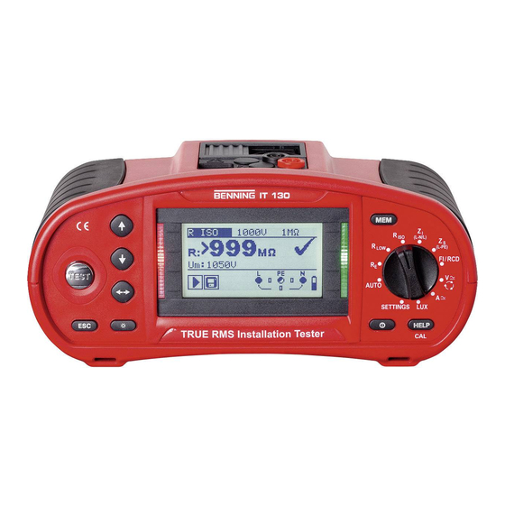
Benning IT 130 Operating Manual (140 pages)
Brand:
Benning
| Category:
Measuring Instruments
| Size: 3.9 MB
Table of Contents
Deutsch
3
Table of Contents
3
Vorwort
6
Warnhinweise
7
Sicherheits- und Bedienhinweise
7
Batterien/Akkus und Ladegerät
11
Normen
13
Gerätebeschreibung
14
Vorderseite
14
Anschlussfeld
15
Rückseite
16
Tragen des Prüfgerätes
17
Befestigung des Trageriemens
18
Lieferumfang und Optionales Zubehör
19
Standard-Lieferumfang
19
Optionales Zubehör
20
Batterieanzeige
21
Warnhinweise und Meldungen
21
Anzeigen und Warntöne
21
Anschlussmonitor
21
Gerätebedienung
21
Bewertungsfeld
22
Warntöne
22
Hilfe-Menü (HELP-Taste)
23
Hintergrundbeleuchtung und Kontrast
23
Funktionswahlschalter
24
AUTO-Schaltstellung
24
SETTINGS-Einstellungen
25
Speicher
25
Sprache
25
Datum und Uhrzeit
26
Erdungssystem (Versorgungsnetz)
26
RCD-Prüfung
27
Isc-Faktor (Skalierungsfaktor)
28
Commander EIN/AUS
28
Werkseinstellungen
29
Einstellungen der Stromzangen
30
Messungen
31
TRMS Spannung, Frequenz und Phasenfolge
31
Isolationswiderstand
33
Niederohmwiderstand/Durchgangsprüfung
35
Niederohmwiderstand mit 200 Ma Prüfstrom
35
Durchgangsprüfung mit 7 Ma Prüfstrom
36
Kompensation (Nullabgleich) des Prüfleitungswiderstandes
37
Prüfen von Fehlerstrom-Schutzeinrichtungen Fi/Rcds
39
Berührungsspannung (Uc)
40
Auslösezeit (RCD T)
41
Auslösestrom (RCD I)
41
Automatikprüfung
42
Schleifenimpedanz und Unbeeinflusster Kurzschlussstrom
45
Leitungsimpedanz und Unbeeinflusster Kurzschlussstrom/Spannungsfall
47
Leitungsimpedanz und Unbeeinflusster Kurzschlussstrom
48
Spannungsfall
49
Erdungswiderstand
51
Prüfung des Schutzleiteranschlusses
53
TRMS Strom über Stromzangenadapter
55
Erstfehler-Leckstrom ISFL IM IT-Netz
56
Beleuchtungsstärke
58
Messwertverwaltung
60
Speicherstruktur
60
Speichern von Messergebnissen
62
Abrufen von Messergebnissen
63
Löschen aller Messungen Pro Speicherplatz und Unterspeicherplätze
64
Löschen von Messergebnissen
64
Löschen des Gesamten Messwertespeichers
64
Löschen einer Einzelnen Messung
65
Umbenennen der Anlagenstrukturfelder
66
Umbenennen der Anlagenstrukturfelder über die PC-Software
66
Umbenennen der Anlagenstrukturfelder über Barcodescanner
66
USB- und RS 232-Schnittstelle
67
Wartung
68
Ersetzen der Sicherungen
68
Reinigung
68
Periodische Kalibrierung
68
Service
69
Technische Daten
70
Isolationswiderstand
70
Allgemeine Daten
71
Fehlerstromschutzeinrichtung FI/RCD
71
Durchgangsprüfung
71
Niederohmwiderstand R LOW
71
Niederohmwiderstand/Durchgangsprüfung
71
Berührungsspannung (Uc)
72
Auslösezeit (RCD T)
72
Auslösestrom (RCD I)
73
Schleifenimpedanz und Unbeeinflusster Fehlerstrom
73
Funktion Zs (Systeme ohne FI/RCD)
73
Funktion Zs Rcd (Systeme mit FI/RCD)
74
Leitungsimpedanz und Unbeeinflusster Kurzschlussstrom/ Spannungsfall
74
Erdungswiderstand
75
TRMS Spannung, Frequenz und Phasenfolge
75
TRMS Spannung (AC/DC)
75
Spannung des Anschlussmonitores
75
Frequenz
75
Phasenfolge (Drehfeld)
76
TRMS Strom (AC/DC) über Stromzangenadapter
76
Erstfehler-Leckstrom ISFL IM IT-Netz
77
Beleuchtungsstärke
77
Allgemeine Daten
78
Anhang A Sicherungstabelle - Unbeeinflusster Kurzschlussstrom
79
Anhang B Standard und Optionales Zubehör Pro Messfunktion
82
Anhang C Commander-Prüfspitze, Commander-Prüfstecker
83
Sicherheitswarnungen
83
Batterien
83
Beschreibung der Commander
84
LED-Anzeigen der Commander
85
Sicherheitshinweise
92
Lieferumfang
92
Gerätebeschreibung
92
Allgemeine Angaben
93
Umgebungsbedingungen
94
Elektrische Angaben
94
Messen mit der BENNING CM
95
Instandhaltung
96
Umweltschutz
97
English
98
Safety Note
99
Scope of Delivery
99
Unit Description
99
General Information
100
Ambient Conditions
101
Electrical Specifications
101
Measuring with the BENNING CM
102
Maintenance
103
Environmental Note
104
Advertisement
Benning IT 130 Operating Manual (87 pages)
Installation Tester
Brand:
Benning
| Category:
Test Equipment
| Size: 3.78 MB
Table of Contents
Table of Contents
3
1 Preface
6
2 Safety and Operating Instructions
7
Warnings
7
Batteries / Storage Batteries and Charger
11
Standards Applied
13
3 Device Description
14
Front Panel
14
Connection Panel
15
Rear Panel
16
Carrying the Installation Tester
17
Attachment of the Carrying Strap
18
Scope of Delivery and Optional Accessories
19
Standard Scope of Delivery
19
Optional Accessories
20
4 Operating the BENNING IT 130 Installation Tester
21
Indications and Acoustic Warning Signals
21
Connection Monitor
21
Battery Indication
21
Warnings and Messages
21
Evaluation Field
22
Acoustic Warning Signals
22
Help Menu ("HELP" Key)
23
Background Lighting and Contrast
23
Function Selector Switch
24
AUTO" Mode
24
SETTINGS" Mode
25
Memory
25
Language
25
Date and Time
26
Earthing System (Power Supply Network)
26
RCD Testing
27
Isc Factor (Scaling Factor)
28
Commander ON/OFF
29
Initial Settings
29
Clamp Settings
30
5 Measurements
32
TRMS Voltage, Frequency and Phase Sequence
32
Insulating Resistance
34
Low-Impedance Resistance / Continuity Test
36
Low-Impedance Resistance with a Testing Current of 200 Ma
36
Continuity Test with a Testing Current of 7 Ma
37
Compensation (Null Balance) of the Test Cable Resistance
38
RCD Testing
40
Contact Voltage (Uc)
41
Tripping Time (Rcdt)
42
Tripping Current (RCD I)
42
Automatic Test
43
Loop Impedance and Prospective Short-Circuit Current
46
Line Impedance and Prospective Short-Circuit Current / Voltage Drop
48
Line Impedance and Prospective Short-Circuit Current
49
Voltage Drop
50
Earthing Resistance
52
Testing the Protective Conductor Connection (PE)
54
TRMS Current by Means of Current Clamp Adapter
56
Single-Fault Leakage Current (ISFL) in IT Networks
57
Luminous Intensity
59
6 Management of Measured Values
61
Memory Structure
61
Saving Measuring Results
63
Recalling Measuring Results
64
Deleting Measuring Results
65
Deleting the Entire Measured Value Memory
65
Deleting All Measurements of each Storage Location and Subordinate Storage Locations
65
Deleting an Individual Measurement
66
Renaming Installation Structure Fields
67
Renaming Installation Structure Fields by Means of the PC Software
67
Renaming the Installation Structure Fields by Means of the Barcode Scanner
67
USB and RS232 Interface
68
7 Maintenance
69
Fuse Replacement
69
Cleaning
69
Periodic Calibration
69
Service
70
8 Technical Data
71
Insulating Resistance
71
Low-Impedance Resistance / Continuity Test
72
Low-Impedance Resistance R LOW
72
Continuity Test
72
Residual Current Protection Devices (Rcds)
72
General Data
72
Contact Voltage (Uc)
73
Tripping Time (RCD T)
73
Tripping Current (RCD I)
74
Loop Impedance and Prospective Short-Circuit Current
75
Zs Function (for Systems Without RCD)
75
Zsrcd Function (for Systems with RCD)
75
Line Impedance and Prospective Short-Circuit Current / Voltage Drop
76
Earthing Resistance
77
TRMS Voltage, Frequency and Phase Sequence
77
TRMS Voltage (AC/DC)
77
Voltage of the Connection Monitor
77
Frequency
77
Phase Sequence (Rotary Field)
77
TRMS Current (AC / DC) Via Current Clamp Adapter
78
Single-Fault Leakage Current (ISFL) in IT Networks
79
Luminous Intensity
79
General Data
80
Appendix A Fuse Table - Prospective Short-Circuit Current
81
Appendix B Standard and Optional Accessories for Specific Measuring Functions
84
Appendix C "Commander" Test Probe, "Commander" Test Plug
85
Safety Warnings
85
Batteries
85
Description of the "Commanders
86
LED Indications of the "Commanders
87
Benning IT 130 Short Instructions (24 pages)
Brand:
Benning
| Category:
Test Equipment
| Size: 2.42 MB
Table of Contents
Table of Contents
3
1 Start-Up Guide
4
Safety and Operational Considerations
4
Front and Connector Panel
6
Standard Scope of Delivery
7
Indications and Meaning of Symbols
8
Selecting Measuring Functions
9
Switch Position „AUTO
10
Settings
10
Measured Value Memory
10
Batteries and Fuses
11
Calibration and Service
12
Optional Accessories
13
2 Measurements
14
Null Balance (Compensation) of the Test Cables
14
TRMS Voltage (V AC/DC), Frequency and Phase Sequence (Rotary Field)
15
Insulation Resistance
16
Iso )
16
Low-Impedance Resistance
17
LOW )/ Continuity Test
17
Residual Current Operated Device (RCD)
18
Loop Impedance (Z Line Impedance (Z Earth Resistance (R )
19
L-Pe )
19
I L-N/L )
20
Current (a AC/DC)
22
Luminous Intensity (LUX)
23
First Fault Current (R ISO ) in IT Supply System (ISFL)
24
Advertisement
Benning IT 130 Short Instructions (24 pages)
Installation Tester
Brand:
Benning
| Category:
Test Equipment
| Size: 4.12 MB
Table of Contents
Table of Contents
3
1 Start-Up Guide
4
Safety and Operational Considerations
4
Front and Connector Panel
6
Standard Scope of Delivery
7
Indications and Meaning of Symbols
8
Selecting Measuring Functions
9
Switch Position „AUTO
10
Settings
10
Measured Value Memory
10
Batteries and Fuses
11
Calibration and Service
12
Optional Accessories
13
2 Measurements
14
Null Balance (Compensation) of the Test Cables
14
TRMS Voltage (V AC/DC), Frequency and Phase Sequence (Rotary Field)
15
Insulation Resistance (R )
16
Low-Impedance Resistance (R )/ Continuity Test
17
Residual Current Operated Device (RCD)
18
Loop Impedance (Z )
19
Line Impedance (Z )
20
Earth Resistance (R )
21
Current (a AC/DC)
22
Luminous Intensity (LUX)
23
First Fault Current (R ) in IT Supply System (ISFL)
24
Advertisement
Related Products
Benning IT 110
Benning IT 120 B
Benning IT 105
Benning IT 105 CH
Benning IT 100
Benning IT 115
BENNING IT 101
Benning 020051
Benning 02826055
Benning 044103
Benning Categories
Measuring Instruments
Test Equipment
Multimeter
Adapter
Transformer
More Benning Manuals
Login
Sign In
OR
Sign in with Facebook
Sign in with Google
Upload manual
Upload from disk
Upload from URL