Table of Contents
Advertisement
Quick Links
Advertisement
Table of Contents

Related Manuals for Benning IT 115


Summary of Contents for Benning IT 115
- Page 1 Quick reference guide Translation of the German original version...
- Page 2 This printed quick reference guide is only an excerpt from the detailed operating manual of the installation tester BENNING IT 115. The latest version of the operating manual can be found on the product website of the BENNING IT 115 for free download in PDF format.
-
Page 3: Table Of Contents
) / continuity test ............... 17 Residual current operated device (RCD) ................18 Loop impedance (Z ) ....................... 19 s L-PE Line impedance (Z ) ......................20 I L-N/L Earth resistance (R ) ......................21 BENNING IT 115 5282 / 03/2023 en... -
Page 4: Start-Up Guide
Warnings related to safety – general information This document is not a supplement to the operating manual! The operating manual can be found on the product website of the BENNING IT 115 for free download in PDF format. http://tms.benning.de/it115 ... - Page 5 Disconnect the "Commander" from the tester and from the installation and switch the "Commander" off before opening the cover of the battery compartment. Dangerous voltages might occur inside the "Commander"! BENNING IT 115 5282 / 03/2023 en...
-
Page 6: Front And Connector Panel
For calibrating the test cables in the R LOW and CONTINUITY function Starts the Z measurement in the sub-function ΔU voltage drop Green LEDs Indicates PASS / FAIL of result. Red LEDs BENNING IT 115 5282 / 03/2023 en... -
Page 7: Standard Scope Of Delivery
Protection cover USB connector Without function 1.3 Standard scope of delivery 1 x BENNING IT 115 installation tester 1 x padded carrying case (item no. 10008291) 1 x test cable with shock-proof plug (item no. 10008295) ... -
Page 8: Indications And Meaning Of Symbols
Instrument is overheated. The measurement is prohibited until the temperature decreases under the allowed limit. High electrical noise was detected during measurement. Results may be impaired. L and N are changed. Warning! High voltage is applied to the test terminals. BENNING IT 115 5282 / 03/2023 en... -
Page 9: Selecting Measuring Functions
Fuse F1, F2 or F3 is defective. If one of the fuses F2 or F3 has blown, the device must not be used anymore. In this case, the device must be sent to BENNING for inspection and repair. Sound warnings Continuous Warning! Dangerous voltage on the PE terminal is detected. -
Page 10: Settings
If one of the fuses F2 or F3 has blown, the device must not be used anymore. In this case, the device must be sent to BENNING for inspection and repair. M 0,315 A / 250 V, 20×5 mm... - Page 11 Fuses F2 and F3 If one of the fuses F2 or F3 has blown, the device must not be used anymore. In this case, the device must be sent to BENNING for inspection and repair. Serial number label Storage batteries/ batteries...
-
Page 12: Calibration
1.9 Service & support Please contact your specialty retailer or the BENNING Service Center for any repair or service work that might be required. Technical support Please contact our Technical support for technical questions on handling the device. -
Page 13: Optional Accessories
Loop and line impedance, insulation, RCD testing, voltage and phase sequence (rotating field) Item no. 044168 BENNING TA 7-16, TA 7-32, TA 7-63 CEE measuring adapter for testing 5-pin CEE sockets, universally applicable due to 4 mm safety sockets BENNING TA 7-16, 16 A (044040) -
Page 14: Measurements
After performing test leads compensation first measured value and then 0.00 Ω is displayed. Successful compensation is displayed by means of the symbol in the "R LOW" and "CONTINUITY" function. Resistance of the test cable before Resistance of the test cables after compensation compensation BENNING IT 115 5282 / 03/2023 en... -
Page 15: Trms Voltage (V Ac/Dc), Frequency And Phase Sequence (Rotary Field)
Ulpe ... Voltage between phase (L) and 1.2.3 .. Clockwise phase sequence: OK protective conductors (PE) 3.2.1 .. Counter-clockwise phase sequence: not OK Unpe .. Voltage between neutral (N) and f ..Frequency protective conductors (PE) f ..Frequency BENNING IT 115 5282 / 03/2023 en... -
Page 16: Iso )
(„MΩ“ flashes on display). Press the key again to finish the measurement. 5. The measuring result will be shown on the display. R ....Insulation resistance Um ....Test voltage (actual value) BENNING IT 115 5282 / 03/2023 en... -
Page 17: Low ) / Continuity Test
R LOW 3. Connection diagrams Connection of the three-wire test cable and of the optional measuring line BENNING TA 5 (044039) Connection of 3-wire test lead and optional “Commander” test probe (044155) 4.b CONTINUITY: 4.a R LOWΩ low impedance... -
Page 18: Insulation Resistance (R Low-Impedance Resistance (R Residual Current Operated Device (Rcd)
Tripping time 5xI ∆N out current I or ∆N x½ .. Tripping time ½×I ∆N end value in I ..Tripping current case the RCD Uc…Contact voltage for didn’t trip ∆N t ..Tripping time BENNING IT 115 5282 / 03/2023 en... -
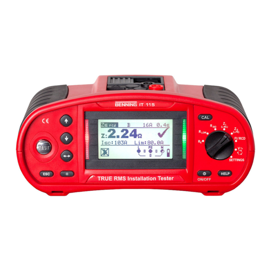
Page 19: Loop Impedance (Z Line Impedance (Z Earth Resistance (R )
4. Press the key 5. The measuring result will be shown on the display. Zs ..Loop impedance (L-PE) Isc ..prospective short-circuit current (fault current) Lim ...lower limiting value of the prospective short-circuit current BENNING IT 115 5282 / 03/2023 en... - Page 20 Isc ..Prospective short-circuit current Isc ..Prospective short-circuit current Lim ...Lower limiting value of the prospective Z ..Line impedance at the measuring point short-circuit current Zref .. Line impedance of the reference point BENNING IT 115 5282 / 03/2023 en...
- Page 21 4. Press the key 5. The measuring result will be shown on the display. R ..Earth resistance Rp ..Probe resistance of the S probe (potential) Rc ..Auxiliary earth electrode resistance of the H probe (current) BENNING IT 115 5282 / 03/2023 en...
- Page 22 BENNING Elektrotechnik und Elektronik GmbH & Co. KG Münsterstraße 135 - 137 D - 46397 Bocholt Phone: +49 2871 93-0 Fax: +49 2871 93-429 Internet: www.benning.de E-mail: duspol@benning.de...
Need help?
Do you have a question about the IT 115 and is the answer not in the manual?
Questions and answers