Table of Contents
Advertisement
Quick Links
Advertisement
Table of Contents

Related Manuals for Benning IT 115


Summary of Contents for Benning IT 115
- Page 1 Installation Tester BENNING IT 115 Operating Manual...
- Page 2 Manufacturer: BENNING Elektrotechnik und Elektronik GmbH & Co. KG Münsterstraße 135 - 137 D - 46397 Bocholt Phone: +49 (0) 2871 - 93 - 0 • Fax: +49 (0) 2871 - 93 - 429 www.benning.de • duspol@benning.de This symbol on your device ensures that the device complies with the requirements laid down by the EU (European Union) with regard to safety and electromagnetic compatibility of devices.
-
Page 3: Table Of Contents
Scope of delivery and optional accessories ............... 18 3.5.1 Standard scope of delivery ................18 3.5.2 Optional accessories ..................18 Operating the BENNING IT 115 installation tester ............19 Indications and acoustic warning signals ..............19 4.1.1 Connection monitor ................... 19 4.1.2 Battery indication .................... - Page 4 BENNING IT 115 Content Testing the protective conductor connection (PE) ............. 49 Maintenance ........................51 Fuse replacement ..................... 51 Cleaning ........................51 Periodic calibration ....................51 Service ........................52 Technical data ......................... 53 Insulating resistance....................53 Low-impedance resistance / continuity test ............... 54 7.2.1...
-
Page 5: Preface
BENNING would like to congratulate you on purchasing this BENNING IT 115 installation tester and its accessories. The BENNING IT 115 installation tester is a multifunctional tester for testing electrical installations in compliance with IEC 60364-6 (DIN VDE 0100-600) and EN 50110 (DIN VDE 0105-100). -
Page 6: Safety And Operating Instructions
Earth (voltage to earth) In order to ensure a high degree of operational safety during the tests and measurements and to avoid damaging of the BENNING IT 115 installation tester, the general warnings listed in the following must be adhered to. - Page 7 BENNING IT 115 Safety and operating instructions Please observe that the measuring category of some accessories might be lower than that of the installation tester. Test probes and "Commander" test probes are provided with detachable protective caps. If these attachable protective caps are removed, the measuring category will be reduced to CAT II.
- Page 8 BENNING IT 115 Safety and operating instructions Remarks with regard to measurements: General icon means that the selected measurement cannot be carried out due to irregular conditions at the input terminals. Carry out measurements of the insulating resistance, low-impedance resistance, continuity and earthing resistance on discharged objects only! The "PASS"...
- Page 9 BENNING IT 115 Safety and operating instructions Loop impedance The lower limiting value of the prospective short-circuit current depends on the fuse type, on the fuse current rating and tripping time as well as on the I scaling factor. The stated accuracy of the parameters tested shall only apply, if the mains voltage is stable during measurement.
-
Page 10: Batteries / Storage Batteries And Charger
Batteries / storage batteries and charger BENNING IT 115 Safety and operating instructions The installation tester can be operated with six alkaline batteries (type AA) or with rechargeable NiMh batteries (storage batteries). The specified operating time refers to storage batteries with a nominal capacity of 2100 mAh. - Page 11 BENNING IT 115 Safety and operating instructions Unpredictable chemical processes might occur during the charging of storage batteries that have not been used for a longer period of time (more than 6 months). In this case, it is recommended to repeat the charging / discharging cycle at least 2 to 4 times.
-
Page 12: Standards Applied
Standards applied BENNING IT 115 Safety and operating instructions The BENNING IT 115 installation tester is manufactured and tested in compliance with the following regulations: Electromagnetic compatibility (EMC) EN 61326-1 Electrical equipment for measurement, control and laboratory use – EMC requirements... -
Page 13: Device Description
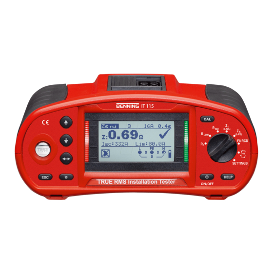
3 Device description Front panel BENNING IT 115 Device description Figure 3.1: Front panel Caption: Matrix display with 128 x 64 pixels and background lighting Modifies selected parameters DOWN Start of measurement TEST PE contact electrode for protective conductor connection... -
Page 14: Connection Panel
Connection panel BENNING IT 115 Device description Figure 3.2: Connection panel Caption: Test connection Measuring inputs / outputs Charging jack For charging rechargeable NiMh storage batteries PS/2 port Serial RS232 interface for service Protective cover USB port Without function! Warnings! -
Page 15: Rear Panel
Fuses F2 and F3 If one of the fuses F2 or F3 has blown, the device must not be used anymore. In this case, the device must be sent to BENNING for inspection and repair. Serial number label - 15 -... -
Page 16: Carrying The Installation Tester
BENNING IT 115 Device description Carrying the installation tester Figure 3.5: Bottom view Caption: Information label Carrying strap openings Lateral covers The installation tester can be carried in different ways by means of the accessories included in the standard scope of delivery. -
Page 17: Attachment Of The Carrying Strap
3.4.1 Attachment of the carrying strap BENNING IT 115 Device description Please choose one of the two methods shown: Figure 3.6: First method Figure 3.7: Alternative method Please check the carrying strap for safe fastening regularly. - 17 -... -
Page 18: Scope Of Delivery And Optional Accessories
Scope of delivery and optional accessories 3.5.1 Standard scope of delivery BENNING IT 115 Device description 1 x BENNING IT 115 installation tester 3.5.2 Optional accessories 1 x padded carrying case (item no. 10008291) 1 x test cable with shock-proof plug (item no. 10008295) 1 x universal three-wire test cable (black, blue, green) (item no. -
Page 19: Operating The Benning It 115 Installation Tester
4 Operating the BENNING IT 115 installation tester Indications and acoustic warning signals 4.1.1 Connection monitor BENNING IT 115 Management of measured values The connection monitor shows the voltages applied to the testing terminals as well as 4.1.2 Battery indication information on active testing terminals in the AC mains. -
Page 20: Evaluation Field
Fuse F1, F2 or F3 is defective. If one of the fuses F2 or F3 has blown, the device must not be used anymore. In this case, the device must be sent to BENNING for inspection and repair. 4.1.5 Acoustic warning signals The measuring result is within the preset limiting values (green LED). -
Page 21: Help Menu ("Help" Key)
4.1.6 Help menu ("HELP" key) BENNING IT 115 Device description HELP Opens the help menu. Help menus are available for all measuring functions. The help menu contains graphic connection diagrams showing how to connect the installation tester to the electrical installation. -
Page 22: Function Selector Switch
Function selector switch BENNING IT 115 Device description The function selector switch is intended for selecting the test and measuring functions "SETTINGS" mode Key functions after having selected the test / measuring function: Selects the sub-function of the adjusted test / measuring function... -
Page 23: Settings" Mode
"SETTINGS" mode BENNING IT 115 Device description Turn the measuring function selector switch to the "SETTINGS" mode in order to make the following settings at the tester: SELECT LANGUAGE (GB, D, E, F, NL) RCD TESTING (according to EN 61008 / EN 61009, IEC 60364-4-41, BS 7671, AS/NZS 3017) 4.3.1 Language... - Page 24 BENNING IT 115 Device description The maximum RCD tripping times vary from standard to standard. The times specified in the individual standards are listed in the following. By default, the tripping times in compliance with the EN 60364-4-41 standard are preset. The EN 60364-4-41 standard defines different tripping times for TN/IT networks and TT networks as can be seen in table 41.1.
-
Page 25: Isc Factor (Scaling Factor)
BENNING IT 115 Device description Maximum testing times and selected testing current for standard (undelayed) RCDs: Standard ½I 2I 5I 4.3.3 Isc factor (scaling factor) EN 60364-4-41 1000 ms 1000 ms 150 ms 40 ms EN 61008 / EN 61009... -
Page 26: Initial Settings
4.3.5 Initial settings BENNING IT 115 Device description Note: The "Commander OFF" (disabled) option is intended for deactivating the operating keys of the "Commander" (except for the background lighting key). It is useful to disable the "Commander", if strong sources of interference might affect the correct functioning of the "Commander". - Page 27 BENNING IT 115 Device description RCD t Nominal differential current: I =30 mA RCD type: AC, undelayed Testing current with initial polarity: (0) Limiting value for contact voltage: 50 V Nominal differential current multiplier: 1 Note: It is also possible to reset the tester to its initial (factory) settings by pressing the "TAB"...
-
Page 28: Measurements
5 Measurements TRMS voltage, frequency and phase sequence BENNING IT 115 Device description The voltages applied to the testing terminals are permanently displayed by means of the connection monitor. In the VOLTAGE TRMS measuring range (true RMS voltage value), the measured values for voltage (AC/DC) and frequency as well as the phase sequence (rotary field) detected can be saved. - Page 29 BENNING IT 115 Device description How to perform voltage measurements Select the function by means of the function selector switch. The display shows VOLTAGE TRMS. Connect the test cables to the test object (see figure 5.2 and figure 5.3). The measurement is performed immediately after the...
-
Page 30: Insulating Resistance
Insulating resistance BENNING IT 115 Device description The measurement of the insulating resistance is performed in order to prove the proper condition of the insulation and in order to exclude electrical danger. Typical applications are the following cases: Insulating resistance between the active conductors (L/N) of an installation and the protective conductor / earth (PE) =>... - Page 31 The warning symbol and the actual voltage will be displayed during discharging. Do not connect the test cables to external voltages higher than 550 V (AC or DC) in order not to damage the BENNING IT 115 installation tester! ...
-
Page 32: Low-Impedance Resistance / Continuity Test
Buzzer ON (sounds if the resistance is lower than the limiting value set) or OFF The resistance measurement is performed with automatic polarity reversal of the testing voltage. Connection plan Figure 5.9: Connection of the three-wire test cable and the optional 40 m measuring line BENNING TA 5 (044039) - 32 - ... -
Page 33: Continuity Test With A Testing Current Of 7 Ma
BENNING IT 115 Device description How to perform low-impedance measurements R LOWΩ Select the function by means of the function selector switch. Set the sub-function to LOWΩ. Set the limiting value (optional). Connect the test cables to the installation tester and compensate the test cable resistance, if necessary (see section 5.3.3 Compensation (null balance) of the test cable... -
Page 34: Compensation (Null Balance) Of The Test Cable Resistance
BENNING IT 115 Device description How to perform continuity tests Select the function by means of the function selector switch. Set the sub-function to CONTINUITY. Set the limiting value (optional). Connect the test cables to the installation tester and compensate the test cable resistance, if necessary (see section 5.3.3 Compensation (null balance) of the test cable resistance). - Page 35 BENNING IT 115 Device description Note: The highest value for test cable compensation is 5 . If the resistance is higher, the compensation value will be reset to the default value. icon is displayed, if the test cable resistance has not been compensated.
-
Page 36: Rcd Testing
RCD testing BENNING IT 115 Device description The testing of RCDs in RCD-protected installations requires various tests and measurements. The measurements are based on the EN 61557-6 standard. The following measurements and tests can be performed: Contact voltage, tripping time, tripping current and... -
Page 37: Contact Voltage (Uc)
BENNING IT 115 Device description Connection plan 5.4.1 Contact voltage (Uc) Figure 5.17: Connection of the optional "Commander" test plug (044149) and the three-wire test cable Leakage current flowing to earth via the protective conductor connection causes a voltage drop at the earthing resistance, i.e. -
Page 38: Tripping Time (Rcdt)
5.4.2 Tripping time (RCDt) BENNING IT 115 Device description Figure 5.18: Example of a contact voltage measurement Results displayed: Uc ..contact voltage RL ..loop resistance (fault loop resistance) The tripping time measurement serves to test the sensitivity of the residual current protection... -
Page 39: Automatic Test
BENNING IT 115 Device description 5.4.4 Automatic test Figure 5.20: Example of a tripping current measurement Results displayed: I ... tripping current Uci ..contact voltage at tripping current I or final value, if RCD does not trip t .... tripping time... - Page 40 BENNING IT 115 Device description Example of the test steps: Step 1 Step 2 Step 3 Step 4 Step 5 Step 6 Step 7 Step 8 Figure 5.21: Test steps of the automatic test Bottom Figure 5.22: The "HELP" key toggles between the upper and the lower part of the result field.
-
Page 41: Loop Impedance And Prospective Short-Circuit Current
Loop impedance and prospective short-circuit current BENNING IT 115 Device description The loop impedance is a complex AC current resistance within a fault loop (earth fault L-PE) consisting of current source, external conductor and protective conductor. The installation tester measures the impedance of the loop and calculates the short-circuit current. The measurement complies with the requirements specified in the EN 61557-3 standard. - Page 42 BENNING IT 115 Device description How to perform loop impedance measurements Select the (L-PE) [English: Z (L-PE)] function by means of the function selector switch. Set the sub-function to Zloop Zsrcd (for systems with RCDs). Set the testing parameters. Connect the test cables to the test object (see figure 5.24).
-
Page 43: Line Impedance And Prospective Short-Circuit Current / Voltage Drop
Line impedance and prospective short-circuit current / voltage drop BENNING IT 115 Device description The line impedance is a complex AC resistance within a current loop (short-circuit L-N or L-L) consisting of current source, external and neutral conductor (single-phase system) or between two external conductors (three-phase system). -
Page 44: Line Impedance And Prospective Short-Circuit Current
5.6.1 Line impedance and prospective short-circuit current BENNING IT 115 Device description Connection plan Figure 5.28: Connection of the optional "Commander" test plug (044149) and the three-wire test cable How to perform line impedance measurements Select the (L-N/L) [English: Z (L-N/L)] function by means of the function selector switch. -
Page 45: Voltage Drop
5.6.2 Voltage drop BENNING IT 115 Device description Note: High fluctuations of the nominal voltage might influence the measuring results ( icon on the LC display). In this case, it is recommended to repeat the measurements and to check whether the measuring results are stable. - Page 46 BENNING IT 115 Device description Results displayed: ΔU .... voltage drop Isc .... prospective short-circuit current Z ....line impedance at the measuring point Zref ..line impedance at the reference point The voltage drop is calculated as follows: with: ΔU ..
-
Page 47: Earthing Resistance
Earthing resistance BENNING IT 115 Device description An adequate and reliably effective earth connection is an important prerequisite for the correct functioning and safety of electrical installations. In combination with the optional earthing kit (044113), it is possible to perform earthing resistance measurements at main earthing systems, lightning arresters and local earth connections. - Page 48 BENNING IT 115 Device description Figure 5.34: Connection of the optional earthing kit (044113) – Measurement at the lightning arrester Figure 5.35: Example of an earthing resistance measurement Results displayed: R ....earthing resistance Rp .... resistance of the S probe, probe resistance (potential) Rc ....
-
Page 49: Testing The Protective Conductor Connection (Pe)
Testing the protective conductor connection (PE) BENNING IT 115 Device description In case of new or modified installations, it might happen that the protective conductor (PE) and the external conductor L (phase) have been accidentally reversed. This is a very dangerous situation! For this reason, it is important to check whether a dangerous phase voltage is applied to the protective conductor connection. - Page 50 BENNING IT 115 Device description Testing the protective conductor connection (PE) Select the (L-N/L) [English: Z (L-PE) [English: Z ] or FI/RCD function by means of the function selector switch. Connect the test cables to the test object (see figure 5.36 and 5.37).
-
Page 51: Maintenance
Do not spill any cleaning liquids on the installation tester! It is important to calibrate the installation tester regularly to make sure that the technical data listed in this operating manual are guaranteed. BENNING waarborgt de naleving van de in de gebruiksaanwijzing vermelde technische gegevens en nauwkeurigheidsinformatie gedurende het 1ste jaar na de leveringsdatum. -
Page 52: Service
Service BENNING IT 115 Maintenance For repairs or service, please contact your specialty retailer or the BENNING Service Center. BENNING Elektrotechnik und Elektronik GmbH & Co. KG Robert-Bosch-Str. 20 D - 46397 Bocholt BENNING Helpdesk phone no.: +49 (0)2871 - 93 - 555 www.benning.de •... -
Page 53: Technical Data
7 Technical data Insulating resistance BENNING IT 115 Technical data Insulating resistance (nominal voltages of 50 V , 100 V and 250 V Measuring range according to EN 61557-2: 0.15 M 199.9 M Measuring range (M) Resolution (M) Accuracy 0.01... -
Page 54: Low-Impedance Resistance / Continuity Test
Low-impedance resistance / continuity test 7.2.1 Low-impedance resistance R LOW BENNING IT 115 Technical data Measuring range according to EN 61557-4: 0.16 1999 Accuracy Measuring range R () Resolution () 0.01 0.00 19.99 (3 % of the measured value + 3 digits) 20.0 ... -
Page 55: Residual Current Protection Devices (Rcds)
Residual current protection devices (RCDs) 7.3.1 General data BENNING IT 115 Technical data Nominal tripping differential current ..10 mA, 30 mA, 100 mA, 300 mA, 500 mA, 1000 mA Accuracy ..........-0 / +0,1I; I = IN, 2IN, 5IN -0.1I... -
Page 56: Tripping Time (Rcd T)
7.3.3 Tripping time (RCD t) BENNING IT 115 Technical data The entire measuring range complies with the requirements specified in the EN 61557-6 standard. 7.3.4 Tripping current (RCD I) Measuring range (ms) Resolution (ms) Accuracy 0.0 40.0 1 ms 0.0 ... -
Page 57: Loop Impedance And Prospective Short-Circuit Current
Loop impedance and prospective short-circuit current 7.4.1 Zs function (for systems without RCD) BENNING IT 115 Technical data Loop impedance Measuring range according to EN 61557-3: 0.25 9.99 k Accuracy Measuring range () Resolution () 0.01 0.00 9.99 ... -
Page 58: Line Impedance And Prospective Short-Circuit Current / Voltage Drop
Line impedance and prospective short-circuit current / voltage drop BENNING IT 115 Technical data Line impedance Measuring range according to EN 61557-3: 0.25 9.99 k Accuracy Measuring range () Resolution () 0.01 0.00 9.99 (5 % of the measured value + 5 digits) 10.0 ... -
Page 59: Trms Voltage, Frequency And Phase Sequence
TRMS voltage, frequency and phase sequence 7.7.1 TRMS voltage (AC/DC) 7.7.2 Voltage of the connection monitor BENNING IT 115 Technical data 7.7.3 Frequency Measuring range (V) Resolution (V) Accuracy 0 550 (2 % of the measured value + 2 digits) Measuring method ......... -
Page 60: General Data
General data BENNING IT 115 Technical data Power supply voltage ......9 V (61.5 V batteries or storage batteries, type AA) Operating time ........typically 20 h Input voltage of charging jack ....12 V 10 % Input current of charging jack ....max. 400 mA Storage battery charging current ... -
Page 61: Appendix A Fuse Table - Prospective Short-Circuit Current
Appendix A Fuse table – Prospective short-circuit current BENNING IT 115 Appendix A – Fuse table Fuse, utilization category gL / gG general-purpose fuse for general applications, mainly for cable and line protection former VDE utilization category, replaced by gG... - Page 62 BENNING IT 115 Appendix A – Fuse table Line safety switch, tripping characteristic B Range of instantaneous tripping: 3 - 5 x I Nominal Disconnection time [s current Minimum prospective short-circuit current (A) Line safety switch, tripping characteristic C Range of instantaneous tripping: 5 - 10 x I...
- Page 63 BENNING IT 115 Appendix A – Fuse table Line safety switch, tripping characteristic K Range of instantaneous tripping: 8 - 14 x I Nominal Disconnection time [s current Minimum prospective short-circuit current (A) Line safety switch, tripping characteristic D Range of instantaneous tripping: 10 - 20 x I...
-
Page 64: Appendix B Standard And Optional Accessories For Specific Measuring Functions
Low-impedance resistance universal three-wire test cable Continuity test "Commander" test probe (switchable by means of "TEST" key) (044155) 40 m measuring line BENNING TA 5 (044039) Line impedance universal three-wire test cable (voltage drop) test cable with shock-proof plug Loop impedance "Commander"... -
Page 65: Appendix C "Commander" Test Probe, "Commander" Test Plug
"Commander" both from the installation tester and from the installation. For repairs or service, please contact your specialty retailer or the BENNING Service Center. The optional "Commanders" can be operated with of two alkaline batteries or two rechargeable NiMh batteries (storage batteries) of size AAA. -
Page 66: Description Of The Optional "Commanders
BENNING IT 115: without function Function selector keys BENNING IT 115: Selection of the measuring function BENNING IT 115: without function BENNING IT 115: Storage / recall of measuring results LCD illumination Switches on / off the LCD illumination of the installation tester... -
Page 67: Led Indications Of The "Commanders
LED indications of the optional "Commanders" BENNING IT 115 Appendix C – Commanders Both LEDs yellow Warning! Phase voltage at the PE connection of the "Commander"! Only indicated, if the silver "TEST" key of the "Commander" is touched for > 1 second!
Need help?
Do you have a question about the IT 115 and is the answer not in the manual?
Questions and answers