Table of Contents
Advertisement
Quick Links
Advertisement
Table of Contents

Subscribe to Our Youtube Channel
Related Manuals for Benning IT 110


Summary of Contents for Benning IT 110
- Page 1 Operating manual Installation Tester BENNING IT 110 / BENNING IT 120 B...
-
Page 2: Table Of Contents
3.2 Connector panel ......................12 3.3 Back panel ........................12 3.4 Bottom view ........................13 3.5 Carrying the BENNING IT 110/ BENNING IT 120 B ............14 3.6 BENNING IT 110/ BENNING IT 120 B set and accessories ..........14 3.6.1 Standard set......................14 3.6.2 Optional accessories....................15 Operation of the BENNING IT 110/ BENNING IT 120 B ..........16... - Page 3 5.6 Phase rotation (phase sequence) ..................41 5.7 Voltage and frequency ....................42 5.8 Testing the PE terminal ....................43 5.9 Resistance to earth (BENNING IT 120 B only) ..............45 5.10 TRUE RMS current (BENNING IT 120 B only) ..............46 5.11 Illumination (BENNING IT 120 B only) ................47 Working with measurement results (BENNING IT 120 B) ........49...
- Page 4 Appendix A Fuse base tables ..................64 10.1 Fuse base tables ......................65 11 Appendix B IT Systems ......................69 11.1 Applicable standards ......................69 11.2 Basic information ......................69 11.3 Measuring guidelines .....................70 11.3.1 Voltage ........................71 11.3.2 Line impedance......................71 11.3.3 FI/RCD testing .......................71 11.3.4 First fault leakage current (ISFL) ................72 11.4 Technical data ........................73 11.4.1...
-
Page 5: Preface
A large graphic matrix display with backlight offers easy to read results, indications, measurement parameters and messages. BENNING IT 110/ BENNING IT 120 B is equipped with all accessories necessary for comfortable testing. It is kept in a soft carrying bag together with all accessories. -
Page 6: Safety And Operational Considerations
Do not use the BENNING IT 110/ BENNING IT 120 B or accessories if any damage is noticed. If a fuse has blown, follow the instructions in the instruction manual to replace it. - Page 7 Remarks concerning the measuring functions General symbol means that the selected measurement cannot be carried out due to irregular conditions at the input terminal. Carry out measurements of insulating resistance, resistance/ continuity test and earth resis- tance at discharged objects only! - The PASS/ FAIL indication is activated when a limiting value has been defined. Choose a limi- ting value which is appropriate for evaluating the measuring results.
-
Page 8: Batteries
Insert cells correctly, otherwise the BENNING IT 110/ BENNING IT 120 B will not operate and the batteries could be discharged. If the BENNING IT 110/ BENNING IT 120 B is not used for a long period of time remove the batteries from their compartment. -
Page 9: Charging
BENNING IT 110/ BENNING IT 120 B now meets the data in the technical specifications. Note: The charger in the BENNING IT 110/ BENNING IT 120 B is a pack cell charger. This means that the cells are connected in series during charging so all of them must be in a similar state (similarly charged, same type and age). -
Page 10: Standards Applied
2.5 Standards applied The BENNING IT 110/ BENNING IT 120 B is manufactured and tested in accordance with the fol- lowing regulations: Safety requirements EN 61010-1:2001 Electromagnetic compatibility (emission and immunity to interference ) EN 61326:2002 Electrical safety in low voltage distribution systems... -
Page 11: Description Of The Benning It 110/ Benning It 120 B
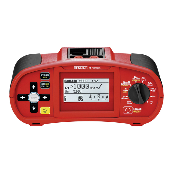
Fig. 3.1: Front panel, example: BENNING IT 120 B Legend: 1 ON/OFF key, to switch on or off the BENNING IT 110/ BENNING IT 120 B The BENNING IT 110/ BENNING IT 120 B is automatically switched off 10 minutes after the last key was pressed or the function selector switch rotated. -
Page 12: Connector Panel
2 Power supply socket 3 Protection connector cover (prevents the simultaneous connection of test cable and charger) BENNING IT 120 B only: In resistance to earth function test, the connector terminals are used as follows: L/L1 black test lead is used for the auxiliary earth electrode (H). -
Page 13: Bottom View
Fig. 3.4: Battery and fuse compartment Legend: 1 Fuse F1 2 Fuse F1 3 Fuse F1 4 Serial number label, a further serial number label is located outside next to the information label 5 Battery cells (size AA) 6 Battery holder 3.4 Bottom view Fig. -
Page 14: Carrying The Benning It 110/ Benning It 120 B
- the test cable is connected to the instrument through the front aperture. 3.6 BENNING IT 110/ BENNING IT 120 B set and accessories 3.6.1 Standard set BENNING IT 110 BENNING IT 120 B... -
Page 15: Optional Accessories
3.6.2 Optional accessories BENNING IT 110 BENNING IT 120 B Optional Current clamp adapter CC 2 (item no. TN 044110) accessories LUXmeter probe, type B (item no. TN 044111) Earthing set consisting of 2 earth rods and 3 test leads... -
Page 16: Operation Of The Benning It 110/ Benning It 120 B
Operation of the BENNING IT 110/ BENNING IT 120 B 4.1 Meaning of symbols and messages on the display of the BENNING IT 110/ BENNING IT 120 B The display is divided into four sections: Fig. 4.1: Display outlook Legend: 1 Function and parameter line In the top display line the measuring function/sub-function and parameters are displayed. -
Page 17: Message Field - Measurement Warnings/Messages
RCD not tripped during the measurement. BENNING IT 110/ BENNING IT 120 B overhea- ted. The temperature of internal components in the BENNING IT 110/ BENNING IT 120 B reached the top limit. Measurement is prohibited until the temperature is lower than that limit. -
Page 18: Result Field
Resistance of auxiliary earth electrode and probe too high. 4.1.4 Result field Measurement passed. Measurement failed. Measurement is aborted. Check the conditions at the in- put terminal. 4.1.5 Other messages Instrument settings and measurement parameters/limits are set to initial (factory) values. For more information re- fer to chapter 4.5.4 Recalling original settings. -
Page 19: Function And Parameter Line
Help menus are available in all functions. The Help menu contains schematic diagrams for illustra- tion how to properly connect the BENNING IT 110/ BENNING IT 120 B to electric installation. After selecting the measurement you want to perform, press the HELP key in order to view the respecti- ve Help menu. -
Page 20: Setup Menu
Rotate function selector switch again to leave the Setup menu or setup sub-menus. Fig. 4.4: Setup menu 4.4.1 Supply system setup The BENNING IT 110/ BENNING IT 120 B enables tests and measurements in the following sup- ply systems: TN (TT) system... -
Page 21: Language Selection
TEST key to activate or to deactivate the COMMANDER. The inactive setting blocks the keys of the COMMANDER (except for the background lighting key). Now, the measurement can only be started or stored by means of the keys at the BENNING IT 110/ BENNING IT 120 B. -
Page 22: Recalling Original Settings
Contrast Prospective short/fault current scaling factor Supply system Communication port (BENNING IT 120 B only) In order to recall the original setting press and hold the key and switch on the instrument. “Hard reset” message will be displayed for a while. -
Page 23: Display Contrast Adjustments
4.5 Display contrast adjustments When low-level backlight is activated press and hold BACKLIGHT key until the Display contrast adjustment menu is displayed. Fig. 4.9: Contrast adjustment menu Use the keys to adjust the contrast level. Press the TEST key to accept the new setting. -
Page 24: Measurements
, ISOLATION/ INSULATION function with the function selector switch. The following menu is displayed: Fig. 5.1: Insulation resistance measurement menu Connect the test cable to the BENNING IT 110/ BENNING IT 120 B. Step 2 Set the following measuring parameters and limit values:... -
Page 25: Resistance/ Continuity Testing
Displayed results: Insulation resistance Test voltage of the BENNING IT 110/ BENNING IT 120 B Save displayed results for documentation purposes. Refer to chapter 6.1 for further information on setting functions and saving of measurement results. (BENNING IT 120 B only) - Page 26 Connect the test cable to the BENNING IT 110/ BENNING IT 120 B. Step 2 Set the following limit value: High limit resistance value Step 3 Before performing the lowΩ measurement, compensate test lead resistance as follows: 1. S hort test lead first as shown in figure 5.5. Fig. 5.5: Shorted test leads 2. P ress the TEST key in order to perform regular measurement. Result close to 0.00 Ω is displayed.
-
Page 27: Continuity
LowΩ resistance sub-result with positive voltage at L terminal R+: R-: LowΩ resistance sub-result with positive voltage at N terminal. Save displayed results for documentation purposes. Refer to chapter 6.1 for further information on setting functions and saving of measurement results (BENNING IT 120 B only). Warning: - L owΩ resistance measurement should only be performed on de-energised objects! - Parallel impedances or transient currents may influence test results. Note: - I f voltage between test terminals is higher than 10 V the RlowΩ measurement will not be performed. - Page 28 Connect the test cable to the BENNING IT 110/ BENNING IT 120 B. Step 2 Set the following limit value: High limit resistance value Step 3 Connect test cable to the item under test. Follow the connection diagram shown in figures 5.10 and 5.11 to perform Continuity measurement. Use the Help function if necessary.
-
Page 29: Testing Rcds
Selected nominal differential current can be multiplied by ½; 1; 2 or 5. 5.3.4 RCD type and test current starting polarity The BENNING IT 110/ BENNING IT 120 B enables testing of general (non-delayed, G) and selec- tive (time-delayed, S) RCDs, which are suited for:... -
Page 30: Testing Selective (Time-Delayed) Rcds
positive Startpolaritat negative Startpolaritat positive starting polarity negative starting polarity (0˚ ) (180˚ ) (0°) (180°) Fig. 5.13: Test current started with the positive or negative half-wave For RCDs of type B, the fault current can be started with positive or negative polarity. - Page 31 Fig. 5.14: Contact voltage measurement menu Connect the test cable to the BENNING IT 110/ BENNING IT 120 B. Step 2 Set the following measuring parameters and limit values: Nominal residual current RCD type Limit contact voltaget Follow the connection diagram shown in figure 5.15 to perform contact voltage measu- Step 3 rement.
-
Page 32: Trip-Out Time
/ . keys to se- lect RCDt (trip-out time of the RCD). The following menu is displayed: Fig. 5.17: Trip-out time measurement menu Connect the test cable to the BENNING IT 110/ BENNING IT 120 B. Step 2 Set the following measuring parameters:... -
Page 33: Trip-Out Current
Select FI/ RCD TEST (RCD) with the function selector switch. Use the keys to se- lect Trip-out current (RCD). The following menu is displayed: Fig. 5.19: Trip-out current measurement menu Connect the test cable to the BENNING IT 110/ BENNING IT 120 B. -
Page 34: Autotest
(contact voltage, loop impedance (fault loop resistance) and trip-out time at different fault currents) in one set of automatic tests, controlled by the BENNING IT 110/ BENNING IT 120 B. If any false parameter is noticed during autotest, the individual parameter test has to be used for further investigation. - Page 35 Connect the test cable to the BENNING IT 110/ BENNING IT 120 B. Step 2 Set the following measuring parameters: Nominal differential trip-out current RCD type Follow the connection diagram shown in figure 5.15 (see the chapter Contact voltage) Step 3 to perform the RCD autotest. Use the Help function if necessary.
- Page 36 After re-switching the RCD the autotest sequence automatically proceeds with step 4. 4. Trip-out time measurement with the following measurement parameters: Test current I ∆N Test current started with the negative half-wave at 180° Measurement normally trips an RCD within allowed time period. The following menu is displayed: Fig.
-
Page 37: Loop Impedance And Prospective Short-Circuit Current (Zs/ Ik)
The loop impedance is a complex AC impedance within the fault loop when a short-circuit to ex- posed conductive parts occurs (conductive connection between phase conductor and protective earth conductor). For measuring the loop impedance (loop resistance), the BENNING IT 110/ BENNING IT 120 B uses a 2.5 A test current. - Page 38 Connect the test cable to the BENNING IT 110/ BENNING IT 120 B. Step 2 Set the following measuring parameters: Fuse type Fuse current rating Fuse trip-out time Appendix A contains a list of different fuse types. Follow the connection diagram shown in figure 5.29 to perform loop impedance measu- Step 3 rement.
-
Page 39: Loop Impedance (Zsrcd)
Select Zs/Ik (L-PE) (loop impedance) with the function selector switch. Use the keys to select the Zs sub-function. The following menu is displayed: Fig. 5.31: Loop impedance measurement menu Connect the test cable to the BENNING IT 110/ BENNING IT 120 B. Step 2 Set the following measuring parameters: Fuse type... -
Page 40: Line Impedance And Prospective Short-Circuit Current
Select Zl/Ik (L-N/ L) (line impedance) with the function selector switch. The following menu is displayed: Fig. 5.33: Line impedance measurement menu Connect the test cable to the BENNING IT 110/ BENNING IT 120 B. Step 2 Set the following measuring parameters:... -
Page 41: Phase Rotation (Phase Sequence)
Low limit of prospective short-circuit current value Save displayed results for documentation purposes. Refer to chapter 6.1 for further information on setting functions and saving of measurement results (BENNING IT 120 B only). Note: The low limit prospective short-circuit current value depends on fuse type, fuse current rating, fuse trip-out time and I -scaling factor. -
Page 42: Voltage And Frequency
Fig. 5.36: Phase sequence test menu Connect the test cable to the BENNING IT 110/ BENNING IT 120 B Follow the connection diagram shown in figure 5.37 to test phase sequence. Step 2 option result 1.2.3 result 2.1.3 Fig. 5.37: Connection of universal test cable and optional three phase cable Step 3 Check the displayed warnings and online voltage/terminal monitor. -
Page 43: Testing The Pe Terminal
Fig. 5.39: Voltage and frequency measurement menu Connect the test cable to the BENNING IT 110/ BENNING IT 120 B. Follow the connection diagram shown in figure 5.40 to perform voltage and frequency Step 2 measurement. Fig. 5.40: Connection diagram Step 3 Check the displayed warnings and online voltage/terminal monitor. Continuous test is running. - Page 44 How to test the PE terminal: Step 1 Connect the test cable to the BENNING IT 110/ BENNING IT 120 B. Follow the connection diagrams in figures 5.42 and 5.43 to test the PE terminal. Step 2 reversed phase and protection conductors most dangerous situation Fig. 5.42: Connection of plug cable and mains outlet...
-
Page 45: Resistance To Earth (Benning It 120 B Only)
5.9 Resistance to earth (R ) ( BENNING IT 120 B only) The BENNING IT 120 B allows resistance to earth measurement using 3-wire measuring me- thod (earthing set). Consider the following instructions when performing resistance to earth measurement: The probe (S) is positioned between the earth electrode (E) and auxiliary earth electrode (H) in the earth reference plane (see figure 5.45). -
Page 46: True Rms Current (Benning It 120 B Only)
The TRUE RMS functions guarantees a correct test result even for non-sinusoidal signals. The current clamp adapter BENNING CC 2 can be used for measuring load currents between 0.5 A and 20 A. -
Page 47: Illumination (Benning It 120 B Only)
Note: Only current clamps with a transformation ratio of 1000:1 should be connected. We recom- mend to use the current clamp adapter BENNING CC 2 which can take measurements from 0.5 A - 20 A. An additional error of the connected current clamp has to be included into the measuring error! Warning: Do not apply voltage to this terminal. - Page 48 Fig. 5.52: Example of illumination measurement result Displayed results: Illumination Save displayed results for documentation purposes. Refer to chapter 6.1 for further information on setting functions and saving of measurement results. (BENNING IT 120 B only). Note: Shadow and irregular incidence affect the measurement result!
-
Page 49: Working With Measurement Results (Benning It 120 B)
Working with measurement results ( BENNING IT 120 B only) After the measurement is completed, all displayed measurement results and parameters can be stored. It is possible to classify, save and recall the measured values directly at the place of mea- surement;... -
Page 50: Recalling Measurement Results
By using the keys set the cursor to the BLOCK line (max. 999). Use the keys to enter the desired element BLOCK xx. By using the keys set the cursor to the FUSE line (max. 999). Use the keys to enter the desired element FUSE xx. In No. -
Page 51: Deleting Measurement Results
Fig. 6.5: Recall results menu Use the keys to select the function for which you want to view results. Press the TEST key to confirm. Fig. 6.6: Examples of recall results menu By using the keys other saved results can be viewed under the same object, block and fuse items. - Page 52 Step 3 Set cursor to the No. line by using the keys set. Fig. 6.8: Delete results menu Use the keys to select the function for which you want to view results. The selec- ted measurement result is shown when the TEST key is pressed, and it is deleted when the TEST key is pressed again.
- Page 53 Continue with instructions under Step 3. Deleting measurement results from the 1rd structure level (OBJECT) By using the keys set cursor to OBJECT line. Use the keys to enter the desired element OBJECT xxx In No. line the number of saved results in the 1st structure level is displayed. Fig.
-
Page 54: Rs232 And Usb Communication (Benning It 120 B Only)
„Spreadsheet“ programmes. How to download saved results to PC Step 1 Connect the BENNING IT 120 B to the PC using the USB or RS232 cable. Make sure that the correct communication port is selected (refer to chapter 4.4.4). Step 2 Start the BENNING PC-Win IT 120 B software. - Page 55 Fig. 7.2: Example of downloaded results Step 4 Edit downloaded structure for documentation purposes.
-
Page 56: Maintenance
Maintenance 8.1 Replacing fuses There are three fuses under the back cover of the BENNING IT 110/ BENNING IT 120 B. M 0.315 A / 250 V, 20×5 mm, T.Nr.: 757211 T his fuse protects internal circuitry of lowΩ resistance function if test probes are connected to the mains supply voltage by mistake.. F2, F3 F 4 A / 500 V, 32×6.3 mm, T.Nr.: 757212... -
Page 57: Technical Specifications
Technical specifications 9.1 Insulation resistance Insulation resistance (nominal voltages 100 V and 250 V Measuring range according to EN61557-2: 0.017 MΩ to 199.9 MΩ Measuring range (MΩ) Resolution (MΩ) Accuracy 0.000 (0.017) - 1.999 0.001 2.00 - 99.99 0.01 ± (5 % of reading + 3 digits) 100.0 - 199.9 Insulation resistance (nominal voltages 500 V and 1000 V Measuring range according to EN61557-2: 0.015 MΩ to 999 MΩ... -
Page 58: Continuity
The number of possible tests with a new set of batteries bis zu 5500 Automatic polarity reversal of the test voltage 9.2.2 Continuity Measuring range (mA) Resolution (mA) Accuracy 0.0 - 99.9 ± (5 % of reading + 3 digits) 100 - 1999 Open-circuit voltage 6.5 V... -
Page 59: Trip-Out Time
Test current max. 0.5×I ∆N Limit contact voltage 25 V, 50 V Fault loop resistance at contact voltage is calculated as: : 0.00 Ω - 10.00 KΩ ∆N 9.3.3 Trip-out time Measuring ranges according to EN61557 General (non-delayed) RCDs Measuring range (ms) Resolution (ms) Accuracy 0 - 300 (½×I ∆N ∆N... -
Page 60: Loop Impedance And Prospective Short-Circuit Current
Trip-out time Measuring range (ms) Resolution (ms) Accuracy ± 3 ms 0 - 300 (AC, A type) ± 3 ms 0 - 140 (B type) Contact voltage Measuring range according to EN61557: 1.0 bis 99.9 V Measuring range (V) Resolution (V) Accuracy 0.0 (3.0) - 9.9 (-0% / +10 %) of reading +2 digits... -
Page 61: Line Impedance And Prospective Short-Circuit Current
9.5 Line impedance and prospective short-circuit current Measuring range according to EN61557-3: 0.26 Ω up to 1999 Ω Measuring range (Ω) Resolution (Ω) Accuracy 0.00 (0.25) - 19.99 0.01 ±(5% of reading + 5 digits) 20.0 - 99.9 100 - 1999 Prospective short-circuit current Measuring range (A) Resolution (A) Accuracy... -
Page 62: Resistance To Earth
9.9 Resistance to earth (BENNING IT 120 B only) Measuring range according to EN61557-5: 0.04 Ω up to 1999 Ω Measuring range (Ω) Resolution (Ω) Accuracy 0.00 (0.02) ÷ 19.99 0.01 20.0 ÷ 99.9 ± (2 % of reading +3 digits) 100 ÷ 1999 Auxiliary earth electrode resistance R 100×R... -
Page 63: General Data
9.12 General data Power supply voltage (6×1.5 V battery cells, size AA) Power supply adapter 12 V - 15 V / 400mA Operation typical 15 h Plug commander (optional) Overvoltage category CAT III / 300 V Overvoltage category CAT III / 600 V, CAT IV / 300 V Protection classification double insulation Pollution degree... -
Page 64: Appendix A Fuse Base Tables
10 Appendix A Fuse base tables Low-voltage fuses (fuse-links) acc. to DIN EN 60269. VDE 0636 (e.g. l.v. h.b.c.) and circuit-brea- kers acc. to DIN EN 60898. VDE 0641 Melting times or trip-out time are depending on current-time characteristics and trip-out current Fuse links are classified in utilisation categories (e.g. gL-gG) Circuit-breakers were formerly characterised with a letter, today, the same letter is also the type designation... -
Page 65: Fuse Base Tables
10.1 Fuse base tables Pros pec- Pros pec- tive short- tive short- Fuse, Fuse, total Fuse, Fuse, Fuse, total Fuse, circuit circuit utilisation clearing rated utilisation clearing rated current current class / type time current class / type time current (A), low (A), low value... - Page 66 Pros pec- Pros pec- tive short- tive short- Fuse, Fuse, total Fuse, Fuse, Fuse, total Fuse, circuit circuit utilisation clearing rated utilisation clearing rated current current class / type time current class / type time current (A), low (A), low value value gL-gG (NV, gG)
- Page 67 Pros pec- Pros pec- tive short- tive short- Fuse, Fuse, total Fuse, Fuse, Fuse, total Fuse, circuit circuit utilisation clearing rated utilisation clearing rated current current class / type time current class / type time current (A), low (A), low value value 35 ms...
- Page 68 Pros pec- Pros pec- tive short- tive short- Fuse, Fuse, total Fuse, Fuse, Fuse, total Fuse, circuit circuit utilisation clearing rated utilisation clearing rated current current class / type time current class / type time current (A), low (A), low value value 0.2 s...
-
Page 69: Appendix B It Systems
Appendix B IT Systems 11.1 Applicable standards EN 60364-4-41, EN 60364-6, EN 60364-7-710, BS 7671 11.2 Basic information The IT system is an power supply network which is isolated from the protective conductor. It is an ungrounded power supply network. Either the network is not connected to earth directly or it is connected to earth via a relatively high impedance. -
Page 70: Measuring Guidelines
The selected IT system remains stored in the device even if the device is switched off. The table below contains the functions of the BENNING IT 120 B as well as remarks concerning the compatibility with IT systems. -
Page 71: Voltage
IT system function Remarks Continuity test R low-Ω independent of the selected power supply network continuity test Insulation independent of the selected power supply network Line impedance line impedance impedance Z L1-L2 prospective short-circuit current for nominal U L1-L2 Fault loop impedance not applicable fault loop impedance prospective fault current... -
Page 72: First Fault Leakage Current (Isfl)
First select the ISOLATION/ INSULATION function by means of the function selector switch. Then, select the „ISFL (first fault current)“ by means of the ▲/▼ keys. The fol- lowing menu is displayed: Figure 11.4: Measuring menu for fault current in case of a first fault Connect the test cable to the BENNING IT 120 B. Step 2 Set the following limiting value: upper current limit for the first fault Step 3 Connect the test cable to the component to be tested. -
Page 73: Technical Data
IT 120 B SPEICHERN HILFE HELP IT 120 B KAL CAL EIN/AUS ON/OFF Figure 11.5: Connection of test commander and universal test cable Step 4 Before measuring, please observe the warnings displayed and the online voltage/ termi- nal monitor. If you do not observe any problems, press the TEST key. After the measu- rement, the measuring results are displayed together with a PASS/ FAIL information (if applicable). -
Page 74: Appendix C Power Supply Network With Lower Voltage
The table below lists the functions of the BENNING IT 120 B intended for testing and measuring of power supply networks. It also contains remarks on compatibility with regard to power supply net- works with lower voltage. -
Page 75: Voltage
Fault loop resistance fault loop resistance both fault loops, R1 (L1-PE) and R2 (L2-PE) prospective fault current and I for both fault loops Voltage, frequency symbols adapted to a power supply network with lower voltage Phase shift automatic recognition of three-phase mains FI/RCD functions contact voltage U for both options, U1 (L1-PE) and U2 (L2-PE) -
Page 76: Loop Resistance And Prospective Fault Current
12.3.4 Loop resistance and prospective fault current The definition of the nominal voltage for calculating I is modified as follows: 55 V for selection of a single-phase center-tapped network, 63 V for selection of a three-phase network. The test can be carried out for both combinations (L1-PE and L2-PE). For each individual test re- sult, the corresponding indication is shown. - Page 77 Contact voltage limiting value 25 V or 50 V (standard) or 2 × I The contact voltage is calculated relating to I (selective). ∆N ∆N For the contact voltage, the fault loop resistance is calculated as follows: ∆ Tripping time The entire measuring range complies with the requirements specified in EN61557-6. The specified accuracies apply to the entire operating range.
-
Page 78: Loop Resistance And Prospective Fault Current
Contact voltage Measuring range (V) Resolution (V) Accuracy 0.0 ÷ 9.9 (-0 %/ +15 % of reading + 2 digits) 10.0 ÷ 99.9 (-0 %/ +15 % of reading) 12.4.2 Loop resistance and prospective fault current Rs sub-function In compliance with EN61557-3, the measuring range is between 0.32 Ω ÷ 1999 Ω. Measuring range (Ω) Resolution (Ω) Accuracy 0.00 ÷... -
Page 79: Line Resistance And Prospective Short-Circuit Current
Nominal input voltage 55 V / 63 V (45 Hz ÷ 65 Hz) Test options L1-PE and L2-PE No tripping of the FI/RCD 12.4.3 Line resistance and prospective short-circuit current Line resistance In compliance with EN61557-3, the measuring range is between 0.25 Ω ÷ 1999 Ω. Measuring range (Ω) Resolution (Ω) Accuracy 0.00 ÷ 19.99 0.01 20.0 ÷... - Page 80 Distributor: Manufacturer: Benning Elektrotechnik & Elektronik GmbH & Co. KG Münsterstraße 135 - 137 D - 46397 Bocholt Phone: +49 (0) 2871 - 93 - 0 • Fax: +49 (0) 2871 - 93 - 429 www.benning.de • E-Mail: duspol@benning.de No part of this publication may be reproduced or utilized in any form or by any means without per- mission in writing from BENNING.
Need help?
Do you have a question about the IT 110 and is the answer not in the manual?
Questions and answers