Kampmann Ultra 73 Series Assembly, Installation And Operating Instructions
Hide thumbs
Also See for Ultra 73 Series:

Related Manuals for Kampmann Ultra 73 Series


Summary of Contents for Kampmann Ultra 73 Series
- Page 1 Ultra ► Assembly, installation and operating instructions Keep these instructions in a safe place for future use! Issue12/22EN SAP No.1389221...
-
Page 3: Table Of Contents
Table of contents 1 General ..........................6 1.1 About these instructions ........................1.2 Explanation of Symbols.......................... 2 Safety............................ 7 2.1 Correct use............................. 2.2 Limits of operation and use........................2.3 Risk from electrocution!......................... 2.4 Personnel requirements - Qualifications ....................11 2.5 Personal Protective Equipment ......................11 3 Transport, storage and packaging.................. - Page 4 6.5.5 Commissioning and functional checks....................... 28 7 Electrical connection......................29 7.1 Maximum electrical rating values ......................29 7.2 Electromechanical control........................30 7.2.1 Connection (**00)............................. 31 7.2.2 Cabling of Ultra (**00), actuation by speed controller type 30510 ............33 7.2.3 Cabling of Ultra (**00), actuation by speed controller type 30510 with industrial thermostat type 30058/ 30059 ............................
- Page 5 11 Faults ............................ 59 11.1 Fault table.............................. 60 11.2 Fault table, electromechanical control ....................61 11.3 Fault table, KaControl, type ..58C1/ 56C1....................61 11.4 KaControl faults ............................. 61 11.5 Start-up after rectification of fault ......................62 12 List of KaControl parameters....................63 12.1 Ultra parameter list..........................
-
Page 6: General
Ultra Assembly, installation and operating instructions General About these instructions These instructions ensure the safe and efficient handling of this equipment. These instructions form an integral part of the equipment and have to be kept in the direct vicinity of the equipment and available to personnel at all times. All personnel must have carefully read through these instructions prior to commencing all work on the equipment. -
Page 7: Safety
Ultra Assembly, installation and operating instructions Safety This section provides an overview of all important safety aspects to ensure optimum protection of personnel as well as safe and trouble-free operation. In addition to the safety instructions in these operating instructions, the valid safety, accident pre- vention and environmental protection regulations must be observed for the area of use of the unit. - Page 8 Ultra Assembly, installation and operating instructions Limits of operation and use Limits of operation Min./max. water temperature °C 5-90 Min./max. air intake temperature °C -20 - (+40) Min./max. air humidity 15-75 Min. operating pressure bar/kPa Max. operating pressure bar/kPa siehe Typenschild Min./max.
-
Page 9: Risk From Electrocution
Ultra Assembly, installation and operating instructions IMPORTANT NOTE! Danger of frost in cooling mode! There is a risk of the heat exchanger freezing when used in unheated rooms. Make sure that the unit is equipped with a frost protection sensor and/or thermostat in this case. IMPORTANT NOTE! Information and limits of operation for cooling mode Pay attention to specific settings and operating modes for cooling with dehumidification of the air:... - Page 10 Ultra Assembly, installation and operating instructions Risk from electrocution! DANGER! Risk of fatal injury from electrocution! Contact with live parts will lead to fatal injury from electrocution. Damage to the insulation or individual components can lead to a fatal injury. Only permit qualified electricians to work on the electrical system.
-
Page 11: Personnel Requirements - Qualifications
Ultra Assembly, installation and operating instructions Personnel requirements - Qualifications Expertise The installation of this product requires specialist knowledge of heating, cooling, ventilation, installation and electrical engin- eering. This knowledge, generally learned in professional training in one of the fields mentioned above, is not described sep- arately. -
Page 12: Transport, Storage And Packaging
IMPORTANT NOTE! Warranty claims can only be made within the applicable period for complaints. (More information is avail- able in the T&Cs on the Kampmann website) IMPORTANT NOTE! 2 people are needed to transport the unit. Wear personal protective clothing when transporting the unit. -
Page 13: Storage
Ultra Assembly, installation and operating instructions Storage Store packaging under the following conditions: Do not store outdoors. Store in a dry and dust-free place. Store in a frost-free place. Do not expose to aggressive media. Protect from direct sunlight. Avoid mechanical vibrations and shocks. IMPORTANT NOTE! Under certain circumstances, packages can carry storage instructions that exceed the requirements listed here. -
Page 14: Technical Data
Ultra Assembly, installation and operating instructions Technical data Unit Ultra Series Water content [l] 1.6 - 2.3 2.0 - 2.9 2.0 – 3.8 2.2 - 4.4 Weight [kg] 28 - 30 34 - 43 35 – 45 45 - 55 EC, 230 V standard 73_58 84_58... -
Page 15: Construction And Function
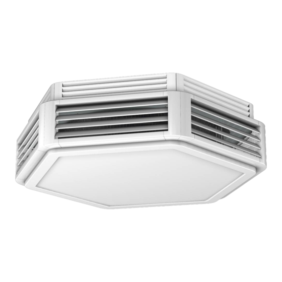
Ultra Assembly, installation and operating instructions Construction and function Overview Fig. 1: Ultra at a glance Base panel Plastic condensate tray (only with cooling unit) Air guide (only with cooling unit) Cu/Al heat exchanger Whisper-quiet, sickle-blade fan, conforms to ErP 2015 Self-supporting plastic housing Condensate pump (hidden), only with cooling unit 6-section intake crown... -
Page 16: Wear Parts List
Ultra Assembly, installation and operating instructions Wear parts list Figure Article Properties Suitable for Art. no. Model 73 and 84 (cannot be used with under-ceiling 154000064050 installation!) For direct installation onto Model 85 (cannot be used Recirculating air filter ele- the intake area of the unit with under-ceiling installa- 154000065050... -
Page 17: Installation And Wiring
Ultra Assembly, installation and operating instructions Installation and wiring Requirements governing the installation site Only install and assemble the unit if the following conditions are met: Make sure that the ceiling is sufficiently load-bearing to take the weight of the unit (Technical data [} 14]). Make sure that the unit is securely suspended/standing. -
Page 18: Installation
Ultra Assembly, installation and operating instructions Type series Voltage [V] Speed [rpm] Max. installation height Throw W[m] H [m] 1000 96_ _58 Installation 2 people are needed to install the unit. CAUTION! Risk of injury from sharp metal housing! The inner metal of the casing can have sharp edges. Wear suitable protective gloves. -
Page 19: Ultra Suspension Points
Ultra Assembly, installation and operating instructions 6.3.1 Ultra suspension points IMPORTANT NOTE! Cutting out the drilling template. The cardboard drilling template is part of the packaging and should be used to position the fixing points on the ceiling. Cut out the drilling template before disposing of the packaging! Fig. 3: Ultra suspension points... -
Page 20: Installation On A Solid Ceiling
Ultra Assembly, installation and operating instructions 6.3.2 Installation on a solid ceiling A: by others B: Scope of delivery x: Maintain this gap to undertake any service work on the intake crown! Make sure that the gap is not filled by subsequent work on the ceiling, such as plastering, as it would then be impossible to fit or remove the intake crown! -
Page 21: Installation On A Suspended Ceiling
Ultra Assembly, installation and operating instructions 6.3.3 Installation on a suspended ceiling A: by others B: Scope of delivery x: Maintain this gap to undertake any service work on the intake crown! Make sure that the gap is not filled by subsequent work on the ceiling, such as plastering, as it would then be impossible to fit or remove the intake crown! - Page 22 Ultra Assembly, installation and operating instructions 6.3.4 Assembly of the intake crown IMPORTANT NOTE! Accessory components are no longer accessible once the intake crown has been fitted! Only fit the intake crown once all connection and installation work has been completed. The motor junction box, valves, motor guard, condensate pump etc.
-
Page 23: Filter Assembly (Accessory)
Ultra Assembly, installation and operating instructions IMPORTANT NOTE! Air intake crown with the unit installed on a solid ceiling The air intake crown cannot be fitted as described when the unit is installed underneath a solid ceiling and the pipework is visible. In this case, it may need to be adapted on site, for instance by removing partial seg- ments of the grille. -
Page 24: Connection To The Pipe Network
Ultra Assembly, installation and operating instructions Hydraulic connection Note the following points when connecting the hydraulic side: Install and test safety components (expansion vessels, pressure relief valves and overflow valves). Allow adequate space for the air flow (air inlet and outlet). 6.4.1 Connection to the pipe network The flow and return connections protrude out of the top of the housing. -
Page 25: Condensation Connection
Ultra Assembly, installation and operating instructions Condensation connection 6.5.1 Installing the condensation drain (with cooling units) Condensate pump SI 30 The self-priming condensate pump is factory-connected to the top of the unit as far as the hose connection spigot for the on- site condensate pressurised line. -
Page 26: Condensate Drainage Using A Condensate Pump
Ultra Assembly, installation and operating instructions Max. delivery height Total hose length (hose diameter 6 mm) 10 m 20 m 30 m 19.2 18.0 16.8 15.3 14.3 18.0 16.8 15.0 14.0 13.8 16.0 15.5 14.4 13.2 12.6 14.3 13.2 11.8 11.0 12.4 11.5... -
Page 27: Ultra Without Kacontrol Module Fitted, Recirculating Air
Ultra Assembly, installation and operating instructions 6.5.3 Ultra without KaControl module fitted, recirculating air Automatically stop cooling operation when the maximum condensate level is reached to prevent the condensate tray from overflowing. Ultra cooling mode Ultra fan motor Cable with plug Condensation pump Mains power supply Float switch... -
Page 28: Commissioning And Functional Checks
Ultra Assembly, installation and operating instructions 6.5.4 Ultra with KaControl module fitted, recirculating air Voltage supply and alarm contact are factory-wired on the Ultra. In the event of an alarm message, the KaControl system closes the valve and the fan is switched to stage 1. Condensation pump Fig. 12: Ultra for cooling 6.5.5 Commissioning and functional checks... -
Page 29: Electrical Connection
Ultra Assembly, installation and operating instructions Electrical connection IMPORTANT NOTE! Condensation formation in the cooling unit! In the event of on-site valve control, the cooling valve must be closed when the fans are switched off. IMPORTANT NOTE! Switch the unit on and off at the control input! Do not switch the unit on and off at the mains, since a fault message is generated for up to 10 seconds after the mains power is switched on! After this time, the EC fan's electronic circuit is ready for operation and a reliable status message is possible. -
Page 30: Maximum Electrical Rating Values
Ultra Assembly, installation and operating instructions Maximum electrical rating values Electromechanical model Type Nominal Mains fre- Active Nominal Leakage cur- Maximum IP protec- Protection voltage [V] quency [Hz] power [kW] current [A] rent [mA] pre-fusing tion rating class 73**58 50/60 0.14 1.27 <3.5... -
Page 31: Connection (**00)
Ultra Assembly, installation and operating instructions 7.2.1 Connection (**00) Voltage supply and activation All sizes require a voltage supply of 230 V / 50/60 Hz and can be activated via a control input of 0-10 VDC (Ri > 49 KOhm). Types 96xx58 and 96xx56 can alternatively be operated via an integral MODBUS RTU interface. - Page 32 Ultra Assembly, installation and operating instructions Refer to these points in the following installation diagrams with electromechanical control: Comply with the details on cable types and cabling with due consideration of VDE 0100. Without *: NYM-J. The requisite number of wires, including PE conductor, is stated on the cable. Cross-sections are not stated, as the cable length is involved in the calculation of the cross-section.
-
Page 33: Cabling Of Ultra (**00), Actuation By Speed Controller Type 30510
Ultra Assembly, installation and operating instructions 7.2.2 Cabling of Ultra (**00), actuation by speed controller type 30510... -
Page 34: Cabling Of Ultra (**00), Actuation By Speed Controller Type 30510 With Industrial Thermostat Type
Ultra Assembly, installation and operating instructions 7.2.3 Cabling of Ultra (**00), actuation by speed controller type 30510 with industrial thermostat type 30058/ 30059 Heating... -
Page 35: Cabling Of Ultra (**00), Actuation By Speed Controller Type 30510 With Room Thermostat Type 30055
Ultra Assembly, installation and operating instructions 7.2.4 Cabling of Ultra (**00), actuation by speed controller type 30510 with room thermostat type 30055 Heating... -
Page 36: Cabling Of Ultra(**00), Actuation By Speed Controller Type 30510 With Clock Thermostat Type 30056
Ultra Assembly, installation and operating instructions 7.2.5 Cabling of Ultra(**00), actuation by speed controller type 30510 with clock thermostat type 30056 Heating... -
Page 37: Cabling Of Ultra (**00), Actuation By Climate Controller Type 30155, 2-Pipe Valve Actuator 230 V Ac
Ultra Assembly, installation and operating instructions 7.2.6 Cabling of Ultra (**00), actuation by Climate controller type 30155, 2-pipe valve actuator 230 V AC, Open/Close... -
Page 38: Cabling Of Ultra (**00), Actuation By Climate Controller Type 30256, 2-Pipe Valve Actuator 230 V Ac
Ultra Assembly, installation and operating instructions 7.2.7 Cabling of Ultra (**00), actuation by Climate controller type 30256, 2-pipe valve actuator 230 V AC, Open/Close... -
Page 39: Cabling Of Ultra (**00), Actuation By Speed Controller Type 30515
Ultra Assembly, installation and operating instructions 7.2.8 Cabling of Ultra (**00), actuation by speed controller type 30515... -
Page 40: Cabling Of Ultra (**00), Actuation By Ddc/Bms, 2-Pipe Valve Actuator 230 V Ac, Open/Close
Ultra Assembly, installation and operating instructions 7.2.9 Cabling of Ultra (**00), actuation by DDC/BMS, 2-pipe valve actuator 230 V AC, Open/Close 2-pipe heating/cooling 2-pipe heating/cooling Unit 2 motor fault Contact open = fault Unit 2 speed (respect unit’s internal resistance!) Unit 1 motor fault Contact open = fault Unit 1 speed... -
Page 41: Kacontrol (*C1)
Ultra Assembly, installation and operating instructions KaControl (*C1) 7.3.1 KaController installation Fig. 15: Installation of flush-mounted back box Electrical connection Connect the KaController to the nearest KaControl unit in line with the wiring diagram. The maximum bus length between the KaController and the KaControl master unit is 30 m. -
Page 42: Connection (*C1)
Ultra Assembly, installation and operating instructions 7.3.2 Connection (*C1) General information Route all low voltage cables along the shortest route. Ensure that low-voltage and power cables are separated, using metal partitions on cable harnesses. Wrong! Use only shielded cables as low-voltage and bus cables. Star-shaped wiring of the bus lines. - Page 43 Ultra Assembly, installation and operating instructions The type of activation is set by 6 DIP switches on the SmartBoard in accordance with the wiring diagram and system config- uration. Fig. 18: SmartBoard DIP switch and potentiometer Control via 0 - 10 VDC The 0-10 VDC control signal at input terminals AI2 and GND (Ri = 20 kOhm) on the SmartBoard is interpreted for speed and valve control according to the following values: Control signal...
- Page 44 Ultra Assembly, installation and operating instructions Install the KaControl recirculation air module. Loosen the screws fixing the module to the bracket. Remove the retaining brackets and place the module loosely on the bracket. Loosen the screw in the shorter leg of the retaining bracket.
- Page 45 Ultra Assembly, installation and operating instructions Remove the smartboard upwards out of the rails. Proceed as follows if the space is tight: Loosen and remove the centre screw in the module hous- Turn the retaining bracket with rail to the left. Remove the smartboard to the front.
-
Page 46: Cabling Of Ultra (*C1), Actuation By Kacontroller Type 321000X, 2-Pipe, 24 V Dc Valve, Open/Close
Ultra Assembly, installation and operating instructions 7.3.3 Cabling of Ultra (*C1), actuation by KaController type 321000x, 2-pipe, 24 V DC valve, Open/Close... -
Page 47: Cabling Of Ultra (*C1), Actuation By Kacontroller Type 321000X, 2-Pipe, 24 V Dc Valve, Open/Close
Ultra Assembly, installation and operating instructions 7.3.4 Cabling of Ultra (*C1), actuation by KaController type 321000x, 2-pipe, 24 V DC valve, Open/Close, with CANbus card... -
Page 48: Cabling Of Ultra (*C1), Actuation By 0-10 V Dc Signal By Others
Ultra Assembly, installation and operating instructions 7.3.5 Cabling of Ultra (*C1), actuation by 0-10 V DC signal by others 2-pipe heating/cooling respect unit’s internal resistance! -
Page 49: Pre-Commissioning Checks
Ultra Assembly, installation and operating instructions Pre-commissioning checks Before initial commissioning, check whether all the necessary conditions have been met so that the unit can function safely and properly. Structural tests Check that the unit is securely standing and fixed. Check the horizontal installation/suspension of the unit. - Page 50 Ultra Assembly, installation and operating instructions Condensation water connection Check whether the condensation tray is free of building rubble. Check the condensation drain and operation of the alarm signal on the condensation pump. Check whether the cooling valve switches off in the event of an alarm signal. Check whether the unit is connected leak-free to the on-site condensation connection.
-
Page 51: Operation
Ultra Assembly, installation and operating instructions Operation Operation of electromechanical control Speed controller, type 30510 The speed controller is used to activate the fan and pre-set the fan speed. Actu- ation of a thermoelectric shut-off valve is not possible. Fig. 23: Speed controller, type 30510 Electronic speed controller, type 30515 With integrated digital timer, protection rating IP 40 230 V, EC, with day, night, week programme, continuously variable fan op-... -
Page 52: Operation Of The Kacontroller
Ultra Assembly, installation and operating instructions Clock thermostat 230 V, type 30256 Electronic clock thermostat for 2- and 4-pipe applications, surface-mounted wall installation on a flush-mounted box in visually unobtrusive design Operation using 4 sensor keys Timer with automatic summer/winter changeover Option for external room sensor Control input for heating/cooling changeover with 2-pipe applications Digital input can be set to Comfort/ECO or ON/OFF switchover... -
Page 53: Function Keys, Display Elements
Ultra Assembly, installation and operating instructions 9.2.1 Function keys, display elements All menus can be selected and set using the navigator dial. The LED background lighting is automatically switched off 5 seconds after the KaController is last used. The LED background lighting can be permanently disabled using a parameter setting. - Page 54 Ultra Assembly, installation and operating instructions The symbols shown on the display depend on the application (2-pipe, 4-pipe etc.) and the parameters set. Fig. 30: Display Display of setpoint room temperature Current time Timer program enabled Weekday Alarm Selected function is locked “External ventilation“...
-
Page 55: Maintenance
Ultra Assembly, installation and operating instructions Maintenance 10.1 Securing against reconnection DANGER! Risk of death by unauthorised or uncontrolled restart! Unauthorised or uncontrolled restarting of the equipment can result in serious injury or death. Before restarting, ensure that all safety devices are fitted and working properly and that there is no haz- ard to humans. -
Page 56: Maintenance Work
Ultra Assembly, installation and operating instructions 10.3 Maintenance work 10.3.1 Visual checks Regular visual checks and simple maintenance, including cleaning the external pump sump and float switch, can be per- formed without removing the housing cover. Simply remove the discharge fins in the discharge field. Fig. 31: Removing fins 10.3.2 Clean the inside of the unit Check all elements that come into contact with air (internal surfaces of the unit, outlet elements etc.) for dirt or deposits dur-... -
Page 57: Cleaning The Condensate Tray
Ultra Assembly, installation and operating instructions 10.3.3 Dismantling the housing cover Note: Remove all snap hooks on the cover from their anchoring before dismantling (risk of breakage)! Dismantle the housing cover for maintenance purposes and visual checks: Fig. 32: Dismantling the housing cover Important! Residual condensate can escape when dismantling the housing cover! 10.3.4 Cleaning the condensate tray With the Ultra cooling model, the condensate tray also needs to be dismantled after the housing cover to provide access to... -
Page 58: Cleaning The Float Switch
Ultra Assembly, installation and operating instructions 10.3.5 Cleaning the float switch Unscrew the plug-in nut and remove the retaining bracket with the float switch fitted. Fig. 36: Retaining bracket of float switch fixed with plug-in nut Open and clean the float switch by removing the cover. Fig. 37: Removing the cover 10.3.6 Replacing the filter. -
Page 59: Faults
Ultra Assembly, installation and operating instructions Faults The following chapter describes possible causes of faults and the work needed to rectify them. Should faults occur frequently, shorten the maintenance intervals in line with the actual loading on the unit. Contact the manufacturer with any faults that cannot be rectified using the following information. Behaviour in the event of faults The following applies: 1. -
Page 60: Fault Table
Ultra Assembly, installation and operating instructions LED code Relay in the fan* Cause Fault, peak current Temperature alarm MODBUS communication fault Tab. 10: Status via flash code * Relay in the fan with factory-programmed function (fault message not inverted) 0 relay de-energised 1 relay energised 11.1 Fault table Fault... -
Page 61: Fault Table, Electromechanical Control
Ultra Assembly, installation and operating instructions Fault Possible cause Remedy Operating unit with integral sensor and/or ex- Place operating unit with integral sensor and/or ternal sensor is exposed to direct sunlight or po- external sensor in a suitable position. sitioned over a heat source. Air cannot blow out or in freely. -
Page 62: Kacontrol Faults
Ultra Assembly, installation and operating instructions 11.4 KaControl faults Code Alarms Priority Faulty control sensor. Motor fault. Room frost protection. Condensation alarm. General alarm. Sensor AI1, AI2 or AI3 faulty. Unit frost protection. EEPROM error. Offline slave in the CAN bus network. Tab. 11: KaControl unit alarms Code Alarms... -
Page 63: List Of Kacontrol Parameters
Ultra Assembly, installation and operating instructions List of KaControl parameters 12.1 Ultra parameter list Parameter Function Standard Min. Max. Unit Ultra P000 Software version P001 Base setpoint for setpoint input ± 3K °C P002 Switching on / off hysteresis for valves K/10 P003 Neutral zone in a 4-pipe system (only in automatic mode) - Page 64 Ultra Assembly, installation and operating instructions Parameter Function Standard Min. Max. Unit Ultra Fan run-on time after operating mode is switched to stage P035 P036 Type of setpoint P037 Display P038 Lock/disable function on control unit P039 Function of digital output V2 (in 2-pipe system) P040 Valve actuation via pulse width modulation Reset time of PI controller to activate the fan in automatic...
- Page 65 Ultra Assembly, installation and operating instructions Parameter Function Standard Min. Max. Unit Ultra P075 Serial address of Slave 5 P076 Serial address of Slave 6 P077 Serial address of Slave 7 P078 Serial address of Slave 8 P079 Serial address of Slave 9 P080 Serial address of Slave 10 P081...
- Page 66 Ultra Assembly, installation and operating instructions Parameter Function Standard Min. Max. Unit Ultra P118 On delay time P119 Off delay time P120 reserved P121 reserved P122 Relative fan speed increase via contact P123 Maximum valve running time P124 Minimum P + I output variation for valve motion (0 to 10) P125 reserved P126...
-
Page 67: Kacontroller Parameter List
Ultra Assembly, installation and operating instructions 12.2 KaController parameter list Para- Function Standard Min. Max. Unit Comment meter Address in Mod- t001 Serial address bus network Baud rate 0 = Baud rate 4800 t002 1 = Baud rate 9600 2 = Baud rate 19200 Background lighting function 0 = Slow fade in, fast fade out t003... -
Page 68: Certificates
Ultra Assembly, installation and operating instructions Certificates... -
Page 69: 153_Eu-Konformitätserklärung_Lufterhitzer
EU-Konformitätserklärung EU Declaration of Conformity Déclaration de Conformité CE Deklaracja zgodności CE EU prohlášení o konformite KAMPMANN Wir (Name des Anbieters, Anschrift): GMBH & Co. KG Friedrich-Ebert-Str. 128-130 We (Supplier’s Name, Address): 49811 Lingen (Ems) Nous (Nom du Fournisseur, Adresse): My (Nazwa Dostawcy, adres): My (Jméno dodavatele, adresa):... - Page 70 Gemäß den Bestimmungen der Richtlinien: Following the provisions of Directive: Conformément aux dispositions de Directive: Zgodnie z postanowieniami Dyrektywy: Odpovídající ustanovení směrnic: 2014/30/EU EMV-Richtlinie 2014/35/EU Niederspannungsrichtlinie Frank Bolkenius Lingen (Ems), den 29.04.2022 ______________________________ Ort und Datum der Ausstellung Name und Unterschrift des Befugten Place and Date of Issue Name and Signature of authorized person Lieu et date d’établissement...
- Page 71 Ultra Assembly, installation and operating instructions Table Tab. 1 Limits of operation ..............................8 Tab. 2 Operating voltage ..............................8 Tab. 3 Water quality................................8 Tab. 4 Technical data – Ultra ............................14 Tab. 5 Technical data ................................ 25 Tab. 6 Flow rate [l/h] of condensate pump –...
- Page 72 Land Kontakt Country Contact Kampmann GmbH & Co. KG Kampmann UK Ltd. Friedrich-Ebert-Str. 128 - 130 Dial House, Govett Avenue 49811 Lingen (Ems) Shepperton, Middlesex, TW17 8AG T +49 591/ 7108-660 T +44 1932/ 228592 Germany Great Britain F +49 591/ 7108-173 F +44 1932/ 228949 E export@kampmann.de...
Need help?
Do you have a question about the Ultra 73 Series and is the answer not in the manual?
Questions and answers