Table of Contents
Advertisement
Quick Links
CY3267
®
PowerPSoC
Lighting Evaluation Kit User Guide
Document No. 001-49266 Rev. *I
WARNING: HIGH-BRIGHTNESS LEDs
CAN CAUSE PERMANENT DAMAGE!
Do not look at the HBLEDs if they are not
covered by the optical diffuser. The
HBLEDs illuminate at a very high intensity
and can cause permanent eye damage.
Use a thick white sheet of paper as a
diffuser if there is no optical diffuser
Cypress Semiconductor
available.
198 Champion Court
WARNING: Generally all lab work in power
San Jose, CA 95134-1709
electronics must be done with extreme
www.cypress.com
care. Caution must be exercised when
using power supplies and power-related
equipment.
Advertisement
Table of Contents

Subscribe to Our Youtube Channel
Related Manuals for Cypress PowerPSoC CY3267


Summary of Contents for Cypress PowerPSoC CY3267
- Page 1 HBLEDs illuminate at a very high intensity and can cause permanent eye damage. Use a thick white sheet of paper as a diffuser if there is no optical diffuser Cypress Semiconductor available. 198 Champion Court WARNING: Generally all lab work in power...
- Page 2 Cypress is not liable, in whole or in part, and you shall and hereby do release Cypress from any claim, damage, or other liability arising from or related to all Unintended Uses of Cypress products.
-
Page 3: Table Of Contents
Contents 1. Introduction Kit Contents .........................5 Additional Learning Resources..................6 Document History ......................7 Documentation Conventions ..................7 2. Getting Started Install Kit Software .......................8 PSoC Designer ......................10 PSoC Programmer ....................12 Install Intelligent Lighting Control GUI ...............13 Install Hardware......................14 2.5.1 Board Wiring Instructions ................14 3. - Page 4 Contents 6. Code Examples Code Example: CY3267_PowerPSoC...............41 6.1.1 Project Description ..................41 6.1.2 Hardware Connections...................41 6.1.3 Program Flow Diagram ..................43 6.1.4 Verify Output ....................43 A. Appendix Schematics ........................44 Bill of Materials ......................46 Safety Precautions.....................48 CY3267 PowerPSoC Lighting Evaluation Kit User Guide, Document No. 001-49266 Rev. *I...
-
Page 5: Introduction
5 PowerPSoC CY8CLED04D01-56LTXI samples ■ Quick start guide ■ Inspect the contents of the kit; if any parts are missing, contact your nearest Cypress sales office for help. CY3267 PowerPSoC Lighting Evaluation Kit User Guide, Document No. 001-49266 Rev. *I... -
Page 6: Additional Learning Resources
Introduction Additional Learning Resources Visit http://www.cypress.com/go/powerpsoc for additional learning resources in the form of datasheets, technical reference manuals, and application notes. CY3267-Power EVK Main Board_Schematic.pdf ■ http://www.cypress.com/go/CY3267 CY3267-Power EVK Main Board_Layout.zip ■ http://www.cypress.com/go/CY3267 ■ CY3267-LED Daughter Board_Schematic.pdf http://www.cypress.com/go/CY3267 CY3267-LED Daughter Board_Layout.zip ■... -
Page 7: Document History
Introduction Document History PDF Creation Origin of Revision Description of Change Date Change 01/23/2009 Initial version of kit guide. 02/10/2011 SNVN Extensive content updates. 06/21/2011 SNVN Text and image updates. 08/08/2012 MKKU Kit guide updated to reflect 64-bit compatibility. Updated sections 2.3 PSoC Programmer 3.3 Programming the 12/04/2012... -
Page 8: Getting Started
To install the kit software, follow these steps: 1. Download and install the CY3267 PowerPSoC Lighting EVK software from http://www.cypress.com/go/CY3267. 2. Select the folder to install the kit-related files. Choose the directory and click Next. 3. Click Install CY3267 PowerPSoC to start the installation, as shown in Figure 2-1. - Page 9 If the required applications are not installed, then the installer prompts you to download and install them. The following software is required: a. PSoC Designer 5.4 or later: Download the latest version from www.cypress.com/go/psocde- signer.
-
Page 10: Psoc Designer
Up to 4 full-duplex UARTs, SPI master and slave, and wireless To use PSoC Designer, follow these steps: 1. Click Start > All Programs > Cypress > PSoC Designer <version> > PSoC Designer <version>. 2. Click File > New Project to create a new project on the PSoC Designer menu or go to File >... - Page 11 3. To experiment with the code examples, go to the Code Examples chapter on page Note For more information about PSoC Designer, go to Help Topics from the following directory: <Install_Directory>\Cypress\PSoC Designer\<version>\PSoC Designer 5\Help CY3267 PowerPSoC Lighting Evaluation Kit User Guide, Document No. 001-49266 Rev. *I...
-
Page 12: Psoc Programmer
To use PSoC Programmer, follow these steps: 1. Click Start > All Programs > Cypress > PSoC Programmer <version> > PSoC Programmer <version>. 2. Use the USB cable to connect the MiniProg to the PC. -
Page 13: Install Intelligent Lighting Control Gui
Figure 2-1. Click Start > All Programs > Cypress > Intelligent Lighting Control. The Intelligent Lighting Control application controls the CY3267 PowerPSoC Lighting EVK over a USB interface from a PC, which runs on Windows XP (SP2 or higher), Vista, or Windows 7 (32-bit and 64-bit) operating system. -
Page 14: Install Hardware
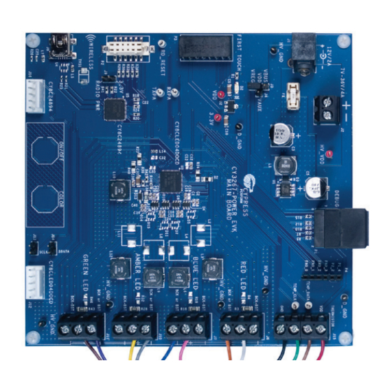
Getting Started Install Hardware 2.5.1 Board Wiring Instructions The CY3267 PowerPSoC EVK main board has five screw-terminal blocks to connect the LED daughter board. The four-post terminal block (J15) is used as the I C interface between PowerPSoC and the thermistor on the LED board. This terminal block contains the following signals: Table 2-1. - Page 15 Getting Started Figure 2-6. CY3267 Power EVK Main Board Wiring Scheme The positive terminal of each LED connector is a common terminal for LED connections in buck topology, boost topology, and buck-boost topology. See Figure 4-2. Figure 2-7. CY3267 Main Board and LED Board Connected/Wired CY3267 PowerPSoC Lighting Evaluation Kit User Guide, Document No.
- Page 16 Getting Started Figure 2-8. CY3267 System Level Diagram PC Running Intelligent Lighting Control Application 12-core Cable Interface I2C Interface CYC24894 Channel USB-I2C Bridge TEMP SENSOR Blue Channel Interface CY8CLED04DOCD1 PowerPSoC Amber Channel CY3267 LED Board +12 V Green Channel CY3267 Main Board CY3267 PowerPSoC Lighting Evaluation Kit User Guide, Document No.
-
Page 17: Kit Operation
Kit Operation Introduction The CY3267 PowerPSoC Lighting EVK ships with factory-installed firmware that demonstrates the ability of PowerPSoC to drive multiple LED channels with color-mixing intelligence. The firmware also illustrates the use of PSoC Designer to design PowerPSoC-based systems and solutions. The factory-installed code example implements the following elements with PowerPSoC: C interface to receive the desired color coordinates and intensity information ■... -
Page 18: Programming The Powerpsoc Device
Kit Operation The CY8C24894 device takes the input from the GUI over the USB interface and passes it on to the PowerPSoC over the I C interface. The PowerPSoC firmware receives the target color coordinates and calculates the intensities of each of the four individual colors (red, green, blue, and amber) using an intelligent color-mixing algorithm. - Page 19 Kit Operation 5. In the Program Part dialog box, verify that the Port Selection field shows the connection to a MiniProg1. Figure 3-2. Program Part Dialog 6. If the board is not powered yet, set the Acquire Mode radio button to Power Cycle. If the board is powered, set the Acquire Mode to Reset.
-
Page 20: Hardware
Hardware CY3267 Power EVK Main Board The CY3267 PowerPSoC Lighting EVK has the following sections: CY3267 Power EVK main board ■ Power supply ❐ PowerPSoC ❐ Programming interface ❐ Debug interface ❐ Connectors and ports ❐ LED board interface ❐ FirstTouch RF interface ❐... - Page 21 Hardware Figure 4-1. CY3267 PowerPSoC Block Diagram J1/J2 External Power Linear DC-DC Supply Regulator Converter 12 V /36 V 3.3 V, Used by Artaflex Radio To SREG For 5 V Generation Inductor/ HBLEDs ISSP Diode Output LED Board POWERPSoC Debug Port Temp Sensor CY8CLED04DOCD1-56LTXI Unused...
-
Page 22: Power Supply
Hardware Table 4-1. CY3267 Power EVK Main Board Specifications Feature Description CY3267 Power EVK main board power source (wall-wart) 12 V D C, 2 A CY3267 Power EVK main board power source (external 32 V DC, 4 A power supply through screw terminals J2) Maximum power consumption 128 W (32 V ×... - Page 23 Hardware Figure 4-4. Power System Structure J3 - PSoC power ■ This header allows you to select the 5-V source from the onboard regulator (VREG), the PowerPSoC auxiliary regulator (VAUX), or from the USB 5-V rail (VBUS). CY3267 PowerPSoC Lighting Evaluation Kit User Guide, Document No. 001-49266 Rev. *I...
- Page 24 Hardware Figure 4-5. External Regulators 4.1.1.1 Grounding Scheme HV_GND - Ground reference for high-voltage HV_VDD net. ■ ■ D_GND - Ground reference for digital 5-V net. Figure 4-6. Star Point for all GND Points CY3267 PowerPSoC Lighting Evaluation Kit User Guide, Document No. 001-49266 Rev. *I...
-
Page 25: Powerpsoc
Hardware 4.1.2 PowerPSoC The CY3267 Power EVK main board is populated with components for the floating-load buck topol- ogy. The floating load buck topology (see Figure 4-8 as an example) consists of two ceramic input bypass capacitors (0.1 µF and 1.0 µF) each rated for 50-V in 0603 package size. These are low equivalent series resistance (ESR) type capacitors. - Page 26 Hardware Figure 4-7. PowerPSoC Connections CY3267 PowerPSoC Lighting Evaluation Kit User Guide, Document No. 001-49266 Rev. *I...
- Page 27 Hardware Figure 4-8. Floating-Load Buck Topology, Single Channel Table 4-2. Pin Description Pin No. Name Description Connected To P1[0] GPIO/I C SDA (Secondary)/ ISSP SDATA ISSP _DATA P2[2] GPIO/Direct Switch Cap connection P4, Extra GPIO P0[3] GPIO/Analog Input (Column 0)/ Analog Output (Column 0) R53, Boost Current Sense, Channel 2 P0[5]...
- Page 28 Hardware Pin No. Name Description Connected To CSN2 Current Sense Negative Input 2 CSP2 Current Sense Positive Input and Power Supply - CSA2 CSP3 Current Sense Positive Input and Power Supply - CSA3 CSN3 Current Sense Negative Input 3 SREGCOMP Voltage Regulator Error Amp Comp SREGFB Regulator Voltage Mode Feedback Node SREGCSN...
-
Page 29: Programming Interface
Hardware 4.1.3 Programming Interface The board also provides the option of using the MiniProg. This interface is faster and the program- ming is done through the 5-pin connector, J12. Headers J13 and J14 allow you to expand the system to support external daughter cards with I capable interfaces. -
Page 30: Debug Interface
This RJ45 receptacle provides a debug interface between the CY8CLED04DOCD device and the ICE-Cube emulation tool using the PSoC Designer software application. The ICE-Cube emulation tool is not provided with this kit. You can purchase it online from http://www.cypress.com/go/CY3215A-DK. Figure 4-10. Debug Interface 4.1.5... -
Page 31: Led Board Interface
3.3-V source and communicates with the CY8C24894 device using the I C protocol. Figure 4-13. FirstTouch RF Interface The FirstTouch RF radio module is not provided with this kit. You can purchase it online from http://www.cypress.com/go/CY3271. CY3267 PowerPSoC Lighting Evaluation Kit User Guide, Document No. 001-49266 Rev. *I... -
Page 32: Artaflex Radio Module Interface
Hardware 4.1.8 Artaflex Radio Module Interface P2 - Artaflex Radio Module Connector This 12-pin connector provides an interface to the Artaflex radio module. The module is powered by a 3.3-V source and communicates with the CY8C24894 device using the SPI protocol. You can obtain Artaflex radio modules from http://www.artaflexmodules.com. -
Page 33: Capsense Buttons
Hardware 4.1.10 CapSense Buttons The CY3267 Power EVK main board has two capacitive sensing elements connected directly to the CY8C24894 PSoC device. If the default firmware is used, the button on the left switches the LEDs on and off while the button on the right cycles through various color combinations displayed on the CY3267 LED daughter board. -
Page 34: Cy3267 Led Daughter Board Functional Description
Hardware 4.1.12 CY3267 LED Daughter Board Functional Description Figure 4-18. CY3267 LED Daughter Board Table 4-3. CY3267 LED Daughter Board Specification Feature Description Power source 5 V (via J15) Maximum power consumption 5 V, 1 mA (5 mW) Board size 3.15 ×... -
Page 35: Cy3267 Power Evk Main Board Interface
Hardware 4.1.14 CY3267 Power EVK Main Board Interface The connections to the CY3267 Power EVK main board interface are brought to the edge of the CY3267 LED Daughter Board and terminated in pads. The wire ends of a cable are soldered to these pads. -
Page 36: Software
Software WARNING: HIGH-BRIGHTNESS LEDs CAN CAUSE PERMANENT DAMAGE! Do not look at the HBLEDs if they are not covered by the optical diffuser. The HBLEDs illuminate at very high intensity and can cause permanent eye damage. Use a thick white sheet of paper as a diffuser if there is no optical diffuser available. -
Page 37: Representing Colors
Software Representing Colors The application has two modes of control: CIE Color Selection Mode and Direct LED Control Mode; Figure 5-1. These two modes are selected using tabs displayed on the upper-left edge of the application window. The CIE Color Selection Mode is the active display when the application is started and is intended to be the most common mode used to control the CY3267 PowerPSoC Light- ing EVK. - Page 38 Software Figure 5-3. Intelligent Lighting Control – Direct LED Control The application can also limit color choices to those that are produced by a black body radiator. A black body radiator is a theoretical, color-neutral object defined by Planck’s Law. A black body radia- tor glows (radiates energy) at different colors as it is heated.
- Page 39 Software Figure 5-4. CIE Color Selection Tab - Color Temperature Control In addition to displaying colors, the application allows you to directly control the LEDs. The state of the LEDs (ON or OFF) is based on a closed loop between the application and the CY3267 Power EVK main board that determines the actual ON/OFF state.
-
Page 40: Led Luminous Flux
Software LED Luminous Flux The luminous flux of the mixed color output can be varied using the Requested Luminous Flux slider located on the right side of the application window. The maximum total flux produced by the LEDs varies, depending upon the chosen color. For example, a neutral white can be set to a higher total flux than any of the four primary colors alone, because the color white is represented by a sum of the light output of each of the LEDs. -
Page 41: Code Examples
Code Examples All code examples are available in the kit CD/DVD or in the following location: <Install_Dir>\Cypress\CY3267 PowerPSoC\<version>\Firmware. Code Example: CY3267_PowerPSoC 6.1.1 Project Description The CY3267 PowerPSoC Lighting EVK includes firmware that demonstrates the ability of PowerPSoC to drive multiple LED channels with color-mixing intelligence. The firmware also illustrates the use of PSoC Designer to design PowerPSoC-based systems and solutions. - Page 42 Code Examples 6.1.2.3 Hysteretic Controller (HYSTCTRL) The HYSTCTRL User Module is intended for use in LED applications as an intelligent controller for high-brightness LEDs. It provides cycle-by-cycle switch control with a fast transient response. The hysteretic controller simplifies system design because it does not require external compensation. The gate drivers are used to drive either internal or external power FETs.
-
Page 43: Program Flow Diagram
Code Examples 6.1.3 Program Flow Diagram Start Enable Global Interrupt Initialize LED’s with Base Value Initialize I2C Interface Initialize PrISM Modules Initialize Hysteric Controllers Enable Current Sense Amplifiers Initialize Each LED’s Coordinates Loop Forever Convert X,Y Coordinates into Tristimulus Values Is Board Are the 3 Controlled By... -
Page 44: Appendix
Appendix The schematics and board layouts are available in the kit CD/DVD or at the following location: <Install_Directory>\Cypress\CY3267 PowerPSoC\<version>\Hardware. Schematics A.1.1 CY3267 LED Daughter Board CY3267 PowerPSoC Lighting Evaluation Kit User Guide, Document No. 001-49266 Rev. *I... - Page 45 A.1.2 CY3267 Power EVK Main Board BOOST BOOST BOOST BOOST BOOST & BUCK-BOOST BOOST & BUCK-BOOST BOOST & BUCK-BOOST BOOST & BUCK-BOOST CY3267 PowerPSoC Lighting Evaluation Kit User Guide, Document No. 001-49266 Rev. *I...
-
Page 46: Bill Of Materials
Bill of Materials Reference Mfr Part Number Description Manufacturer C1,C15,C23,C34,C39 UMK107C5105KA-T CAP CER 1.0UF 50V X5S 0603 Taiyo Yuden C2,C16,C24,C40 ECJ-1VB1H104K CAP CERAMIC .1UF 50V X7R 0603 Panasonic - ECG EEE-FK1H101P CAP ELECT 100UF 50V FK SMD Panasonic - ECG EEE-FK1J680UP CAP ELECT 68UF 63V FK SMD Panasonic - ECG... - Page 47 LM2597M-5.0/NOPB IC REG SIMPLE SWITCHER 8-SOIC National Semiconductor AP130-33YRL-13 IC REG LDO 300mA 3.3V SOT89R Diodes Inc CY8CLED04DOCD- 56QFN Power PSoC Device Cypress Semiconductor 56LTXI CY8C24894-24LFXI PSoC Mixed-Signal Array Cypress Semiconductor 1902E STANDOFF HEX FLA-RET 4-40 1.000" Keystone Electronics NY PMS 440 0038 PH...
-
Page 48: Safety Precautions
Safety Precautions A.3.1 General Safety Precautions Keep your work area clean. Ensure that there are no loose wires or metal pieces on the table or ■ near high-power circuits. Always wear safety glasses when working with circuits at high power or high voltage. ■...
Need help?
Do you have a question about the PowerPSoC CY3267 and is the answer not in the manual?
Questions and answers