Table of Contents
Advertisement
Quick Links
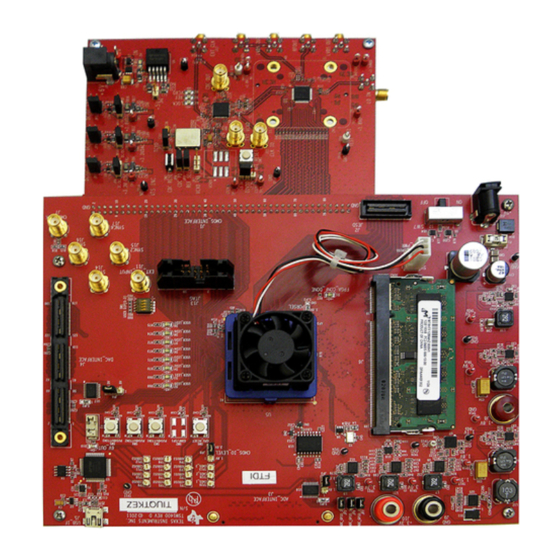
This is the user's guide for the AFE707xEVM evaluation module (EVM). The AFE7070/71 is a dual 14-bit
65-MSPS digital-to-analog converter with an integrated quadrature modulator. The NCO and LVDS output
functions are not available with the AFE7071 but the AFE7070 has both functions. This is the sole
difference between the AFE7070 and the AFE7071. Hereafter, the AFE707x is referred to as AFE7070.
The EVM also includes the CDCM7005 clock synchronizer, which provides the necessary clocks for the
AFE and pattern generator. This EVM is ideally suited for mating with the TSW3100 pattern generation
card for evaluating WCDMA, LTE, or other high-performance modulation schemes.
1
1.1
1.2
1.3
1.4
1.5
2
2.1
2.2
3
3.1
3.2
3.3
3.4
3.5
1
EVM Block Diagram
2
3
4
5
6
7
8
9
SLOU337 - March 2012
Submit Documentation Feedback
AFE707xEVM Evaluation Module
.........................................................................................................
...............................................................................................
.................................................................................................
.............................................................................................
...................................................................................................
.............................................................................................
............................................................................................................
............................................................................................
................................................................................................
.......................................................................................................
................................................................................................
...........................................................................................
.................................................................................
.................................................................................
List of Figures
........................................................................................................
...................................................................................................
.............................................................................................
..........................................................................................
.................................................................................................
Copyright © 2012, Texas Instruments Incorporated
Contents
.........................................................................
.........................................................................
.....................................................
..............................................
AFE707xEVM Evaluation Module
User's Guide
SLOU337 - March 2012
2
2
2
2
3
4
5
5
5
7
7
8
8
10
11
2
4
5
7
8
9
10
...............
11
11
1
Advertisement
Table of Contents

Related Manuals for Texas Instruments AFE7070


Summary of Contents for Texas Instruments AFE7070
-
Page 1: Table Of Contents
SLOU337 – March 2012 AFE707xEVM Evaluation Module This is the user’s guide for the AFE707xEVM evaluation module (EVM). The AFE7070/71 is a dual 14-bit 65-MSPS digital-to-analog converter with an integrated quadrature modulator. The NCO and LVDS output functions are not available with the AFE7071 but the AFE7070 has both functions. This is the sole difference between the AFE7070 and the AFE7071. -
Page 2: Hardware Overview
Hardware Overview www.ti.com Hardware Overview This section describes the EVM hardware and how it can be modified to evaluate the AFE7070 in various configurations. EVM Block Diagram Figure 1 shows a simplified block diagram of the EVM in its default configuration. -
Page 3: Clocking Options
Dual Output Clock Mode In Dual Output Clock mode, the AFE7070’s CLKIO pin becomes an output that can be used to drive a digital source such as the TSW3100. To use this mode, the user must remove resistor R18 connecting CLKIO to the CDCM7005’s output and instead populate resistor R25. -
Page 4: Power Supply Options
2-to-1 impedance ratio of the transformer used for single-ended-to-differential conversion. Note that depending on the AFE7070’s clock mode, you may need to be send separate clock signals to CLKIO or to the digital source as well. The SMA connector J11 can supply CLKIO, providing that you install resistor R25 and remove R18. -
Page 5: Software Control
Power. These controls consist of binary switches that toggle various power-down and sleep states. • SYNC Settings. These settings control the device synchronization. The switch marked Synchronize corresponds to the SYNC bit in the AFE7070 register map, and activating this switch writes a 1 to this bit. •... - Page 6 The CDCM7005 tab provides full programming control of the CDCM7005 device. Figure 4 displays a screen shot of this tab. . Not all of the functions may be of interest in evaluating AFE7070 performance. The tab is divided into three sections: •...
-
Page 7: Basic Test Procedure
Register Controls – Send All. This command sends all the GUI settings to the AFE7070 and CDCM7005 registers. – Read All. This command reads back the register values of the AFE7070 and display them in the display pane. – Load Regs. This command loads the contents of a text file into both the AFE7070 and CDCM7005 registers (as applicable). -
Page 8: Test Setup Connections
Press the green Create and Save/Run TSW3100 button. CommsSignalPattern Setup from Default Configuration (WCDMA) • Change Interpolation value to DAC Clock Rate / 3.84 (i.e. 57.6 / 3.84 = 15). AFE707xEVM Evaluation Module SLOU337 – March 2012 Submit Documentation Feedback Copyright © 2012, Texas Instruments Incorporated... -
Page 9: Tsw3100 Multitonepattern Programming Gui
• Check the LOAD and Run, Interleaved, and 16b MSB Justify boxes. • Press the green Create button. Figure 6. TSW3100 MultiTonePattern Programming GUI SLOU337 – March 2012 AFE707xEVM Evaluation Module Submit Documentation Feedback Copyright © 2012, Texas Instruments Incorporated... -
Page 10: Afe7070 Software Quick-Start Guide
Select the CDCM7005 tab to adjust the output clock signals: – Y1 (AFE7070’s CLK_IO) must be LVCMOS, with Y1A set to active rather than 3-state. – Y3 (AFE7070’s DACCLK) must be LVPECL, with both Y3A and Y3B set to active. -
Page 11: Afe7070 Performance Results
Basic Test Procedure www.ti.com AFE7070 Performance Results Figure 8 Figure 9 shows the typical two-tone and ACPR performance of the AFE7070 EVM from the preceding setup. RBW 3 kHz Delta 1 [T1 ] VBW 300 kHz -50.33 dB 0.5 dBm... - Page 12 Any exceptions to this are strictly prohibited and unauthorized by Texas Instruments unless user has obtained appropriate experimental/development licenses from local regulatory authorities, which is responsibility of user including its acceptable authorization.
- Page 13 FCC Interference Statement for Class B EVM devices This equipment has been tested and found to comply with the limits for a Class B digital device, pursuant to part 15 of the FCC Rules. These limits are designed to provide reasonable protection against harmful interference in a residential installation. This equipment generates, uses and can radiate radio frequency energy and, if not installed and used in accordance with the instructions, may cause harmful interference to radio communications.
- Page 14 Also, please do not transfer this product, unless you give the same notice above to the transferee. Please note that if you could not follow the instructions above, you will be subject to penalties of Radio Law of Japan. Texas Instruments Japan Limited (address) 24-1, Nishi-Shinjuku 6 chome, Shinjukku-ku, Tokyo, Japan http://www.tij.co.jp...
- Page 15 FDA Class III or similar classification, then you must specifically notify TI of such intent and enter into a separate Assurance and Indemnity Agreement. Mailing Address: Texas Instruments, Post Office Box 655303, Dallas, Texas 75265 Copyright © 2012, Texas Instruments Incorporated...
- Page 16 Any exceptions to this are strictly prohibited and unauthorized by Texas Instruments unless user has obtained appropriate experimental/development licenses from local regulatory authorities, which is responsibility of user including its acceptable authorization.
- Page 17 FCC Interference Statement for Class B EVM devices This equipment has been tested and found to comply with the limits for a Class B digital device, pursuant to part 15 of the FCC Rules. These limits are designed to provide reasonable protection against harmful interference in a residential installation. This equipment generates, uses and can radiate radio frequency energy and, if not installed and used in accordance with the instructions, may cause harmful interference to radio communications.
- Page 18 Also, please do not transfer this product, unless you give the same notice above to the transferee. Please note that if you could not follow the instructions above, you will be subject to penalties of Radio Law of Japan. Texas Instruments Japan Limited (address) 24-1, Nishi-Shinjuku 6 chome, Shinjuku-ku, Tokyo, Japan http://www.tij.co.jp...
- Page 19 FDA Class III or similar classification, then you must specifically notify TI of such intent and enter into a separate Assurance and Indemnity Agreement. Mailing Address: Texas Instruments, Post Office Box 655303, Dallas, Texas 75265 Copyright © 2012, Texas Instruments Incorporated...
- Page 20 IMPORTANT NOTICE Texas Instruments Incorporated and its subsidiaries (TI) reserve the right to make corrections, enhancements, improvements and other changes to its semiconductor products and services per JESD46, latest issue, and to discontinue any product or service per JESD48, latest issue.
Need help?
Do you have a question about the AFE7070 and is the answer not in the manual?
Questions and answers