
Related Manuals for Keysight Technologies E8364-60108


Summary of Contents for Keysight Technologies E8364-60108
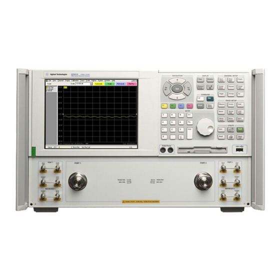
- Page 1 Installation Note Keysight For E8363B/C and E8364B/C PNA Series Microwave Network Analyzers Source Attenuators and Bias Tees Upgrade Kit Upgrade Kit: E8364-60108...
- Page 2 No additional DOCUMENT THAT CONFLICT WITH government requirements THESE TERMS, THE WARRANTY beyond those set forth in the © Keysight Technologies, Inc. TERMS IN THE SEPARATE EULA shall apply, except to the 2003-2016 AGREEMENT WILL CONTROL. extent that those terms, rights, or...
-
Page 3: Table Of Contents
Contents Table of Contents 1. General Information Getting Assistance from Keysight ..........1 Contacting Keysight . -
Page 4: General Information
Keysight E8363B/C and E8364B/C Source Attenuators and Bias Tees Upgrade Kit Installation Note General Information Getting Assistance from Keysight By internet, phone, or fax, get assistance with all your test and measurement needs. Contacting Keysight Assistance with test and measurements needs and information on finding a local Keysight office are available on the Web at: www.keysight.com/find/assist If you do not have access to the Internet, please contact your Keysight field... -
Page 5: About Installing The Upgrade Kit
General Information About Installing the Upgrade Kit About Installing the Upgrade Kit IMPORTANT! Option UNL can only be installed on analyzers with the option combinations listed below as “Products affected”. If your analyzer does not have the proper options (as listed below), it will be necessary to install those options BEFORE installing this option (Option UNL). -
Page 6: Items Included In The Upgrade Kit
Check the contents of your kit against this list. If any item is missing or “Getting Assistance from damaged, contact Keysight Technologies. Refer to Keysight” on page Table 1 Contents of Option UNL Upgrade Kit (E8364-60108) Ref. Description Part Number Desig. -
Page 7: Installation Procedure For The Upgrade Kit
General Information Installation Procedure for the Upgrade Kit Table 1 Contents of Option UNL Upgrade Kit (E8364-60108) Ref. Description Part Number Desig. These parts are for analyzers WITH Option 014 AND Option 081 Lower front panel overlay (Option UNL/014) E8364-80011... -
Page 8: Electrostatic Discharge Protection
General Information Installation Procedure for the Upgrade Kit Electrostatic Discharge Protection Protection against electrostatic discharge (ESD) is essential while removing or connecting cables or assemblies within the network analyzer. Static electricity can build up on your body and can easily damage sensitive internal circuit elements when discharged. -
Page 9: Tools And Equipment Required For The Installation
General Information Installation Procedure for the Upgrade Kit Step 3. Raise the Receiver Deck. Step 4. Remove the Existing Cables. Step 5. Install the Attenuators and Bias Tees. Step 6. Install the Option UNL Cables. Step 7. Lower and Fasten the Receiver Deck and Connect the Bias Tee Control Cables. Step 8. - Page 10 General Information Installation Procedure for the Upgrade Kit Step 1.Remove the Outer Cover This procedure is best performed with the analyzer resting on its front handles in the vertical position. Do not place the analyzer on its front panel . This will damage the front panel assemblies. without the handles Figure 2 Refer to...
- Page 11 General Information Installation Procedure for the Upgrade Kit Figure 2 Outer Cover Removal The figure above shows the E8363/4B front panel and floppy disk drive. The E8363/4C front panel has a slightly different appearance and does not include a floppy disk drive. Step 2.Remove the Front Panel Assembly (Option 014 Only) Refer to for this procedure.
- Page 12 General Information Installation Procedure for the Upgrade Kit ③ 4. Disconnect the front panel interface ribbon cable (item ) from the A3 front panel interface board. The front panel is now free from the analyzer. Figure 3 Front Panel Assembly Removal The figure above shows the E8363/4B front panel and floppy disk drive.
- Page 13 General Information Installation Procedure for the Upgrade Kit Step 3.Raise the Receiver Deck Refer to for this procedure. Figure 4 1. Place the analyzer bottom-side up on a flat surface. ① 2. With a T-10 TORX driver, remove the four screws, (item ), that secure the receiver deck.
- Page 14 General Information Installation Procedure for the Upgrade Kit Step 4.Remove the Existing Cables Analyzers WITHOUT Option 014 Figure 5 Refer to for the following procedure. Remove the following cables: — W7E8364-20025A23 detector to A28 channel R1 mixer — W8E8364-20026A24 detector to A29 channel R2 mixer —...
- Page 15 General Information Installation Procedure for the Upgrade Kit Analyzers WITH Option 014 but WITHOUT Option 081 Refer to Figure 6 for the following procedure. Remove the following cables: — W63E8364-20073PORT 1 CPLR THRU to A25 test port 1 coupler — W61E8364-20081A22 switch splitter to PORT 1 SOURCE OUT —...
- Page 16 General Information Installation Procedure for the Upgrade Kit Analyzers WITH Options 014 AND 081 Refer to Figure 7 for the following procedure. Remove the following cables: — W63E8364-20073PORT 1 CPLR THRU to A25 test port 1 coupler — W61E8364-20081A22 switch splitter to PORT 1 SOURCE OUT —...
- Page 17 General Information Installation Procedure for the Upgrade Kit Figure 7 Cable Removal, Analyzers with Options 014 and 081 Keysight E8363B/C and E8364B/C Installation Note...
- Page 18 General Information Installation Procedure for the Upgrade Kit Step 5.Install the Attenuators and Bias Tees Figure 8 Refer to for this portion of the procedure. To install the attenuators and bias tees, the brackets holding the detectors must be removed. 1.
- Page 19 General Information Installation Procedure for the Upgrade Kit 4. Attach one step attenuator to each bracket using two M3.0 x 8 screws (provided) for each. Be careful to position the step attenuators so that the necessary cables can be attached. The end of the step attenuator with the ribbon cable connector must face toward the inside of the analyzer.
- Page 20 General Information Installation Procedure for the Upgrade Kit Step 6.Install the Option UNL Cables Analyzers WITHOUT Option 014 Figure 10 on page 18 Refer to for the following procedure. The new parts are Table 1 on page listed in 1. Install the following cables in the order listed: ①...
- Page 21 General Information Installation Procedure for the Upgrade Kit Figure 10 Cable Installation, Analyzers without Option 014 Analyzers WITH Option 014 but WITHOUT Option 081 Figure 11 on page 19 Refer to for the following procedure. The new parts are Table 1 on page listed in 1.
- Page 22 General Information Installation Procedure for the Upgrade Kit — W56E8364-20168A39 bias tee to A26 test port 2 coupler — W55E8364-20167A38 bias tee to A25 test port 1 coupler — W82E8364-20054A37 step attenuator to PORT 2 SOURCE OUT — W84E8364-20040PORT 2 CPLR THRU to A39 bias tee —...
- Page 23 General Information Installation Procedure for the Upgrade Kit Analyzers WITH Options 014 AND 081 Refer to Figure 11 on page 19 for the following procedure. The new parts are Table 1 on page listed in 1. Install the following cables in the order listed: ①...
- Page 24 General Information Installation Procedure for the Upgrade Kit Figure 12 Cable Installation, Analyzers with Options 014 and 081 Keysight E8363B/C and E8364B/C Installation Note...
- Page 25 General Information Installation Procedure for the Upgrade Kit Step 7.Lower and Fasten the Receiver Deck and Connect the Bias Tee Control Cables Figure 13 Refer to for this procedure. ✍ 1. Pull the latch pin (item ) toward the center of the analyzer to release the receiver deck.
- Page 26 General Information Installation Procedure for the Upgrade Kit Step 8.Replace the Lower Front Panel Overlay (Option 014 Only) The new parts referenced in this procedure are listed in Table 1 on page Figure 14 Refer to for this procedure. 1. From the back side of the front panel, use a blunt object in one of the ①...
- Page 27 General Information Installation Procedure for the Upgrade Kit Step 9.Reinstall the Front Panel Assembly and Front Panel Jumpers (Option 014 Only) Before removing the front panel from the analyzer, lift and support the front of the analyzer chassis. Figure 15 on page 25 Refer to for this procedure.
- Page 28 General Information Installation Procedure for the Upgrade Kit Figure 15 Front Panel Assembly Reinstallation The previous figure and the figure below show the E8363/4B front panel and floppy disk drive. The E8363/4C front panel has a slightly different appearance and does not include a floppy disk drive. Keysight E8363B/C and E8364B/C Installation Note...
- Page 29 General Information Installation Procedure for the Upgrade Kit Step 10.Reinstall the Outer Cover This procedure is best performed with the analyzer resting on its front handles in the vertical position. Do not place the analyzer on its front panel . This will damage the front panel assemblies. without the handles Figure 16 Refer to...
- Page 30 3. Click OK when done. If Option UNL has not been enabled, perform “Enable Option UNL” again. If the option is still not enabled, contact Keysight Technologies. Refer to “Getting Assistance from Keysight” on page Keysight E8363B/C and E8364B/C Installation Note...
- Page 31 General Information Installation Procedure for the Upgrade Kit Step 12.Perform Post-Upgrade Adjustments and Calibration The following adjustments must be made due to the change in the full frequency range of the analyzer. — source calibration — receiver calibration These adjustments are described in the PNA service guide and in the PNA on-line HELP.
- Page 32 This information is subject to change without notice. © Keysight Technologies 2003-2016 Edition 1, October 2016 www.keysight.com...
Need help?
Do you have a question about the E8364-60108 and is the answer not in the manual?
Questions and answers